

I almost missed it. That’s the part that still bothers me.
Two winters ago, a haul truck at a mine site in northern Alberta rolled into the maintenance bay with a dead instrument cluster. The engine ran. The transmission shifted manually. But the dash was dark, and every ECU on the J1939 backbone was throwing Timeout errors like confetti.
The junior tech had already done what you’d expect: ohmed out the backbone, checked the 120Ω terminators at both ends, wiggled every Deutsch connector he could reach. All clean. The resistors measured 60Ω across the bus with power off — exactly what you want to see. By every conventional J1939 diagnostic check, that network should have been running perfectly.
Then he scoped it.
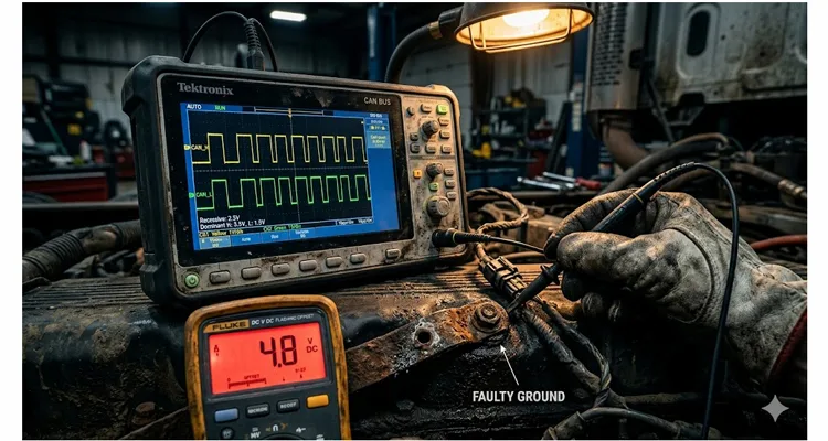
And here’s the thing that nearly sent us down a rabbit hole we’d still be digging: the scope showed CAN_H and CAN_L swinging exactly the way they should — recessive at 2.5V, dominant with CAN_H bumping to roughly 3.5V and CAN_L dipping to about 1.5V. The differential waveform? A textbook 2V peak-to-peak square wave. Clean edges, no ringing, no visible noise.
If you had walked past the scope at that moment, you would have said, “Bus looks fine. Must be a software issue.”
You would have been wrong.
The Hidden Dimension That Sits Right on the Scope Screen
What we missed — what a lot of people miss — was the common-mode voltage.
Here’s a way to picture what was happening without diving into semiconductor physics. Every CAN transceiver contains a comparator tuned to detect a 2-volt gap between the two bus lines. When the network sends a dominant bit, CAN_H rises while CAN_L falls, opening up that voltage gap. The receiver just checks whether the gap is present or not — it doesn’t care if the absolute voltage on both wires is 3 volts or 30 volts, so long as the gap is there. This is the whole reason twisted-pair CAN wiring shrugs off electrical noise: any interference that hits both wires equally gets subtracted out before the receiver ever sees it.
But here’s the catch. That comparator has a limited input window, called the common-mode input range. Imagine taking the entire differential signal — both CAN_H and CAN_L together — and lifting them up by 3 volts. The gap between the two lines doesn’t change one bit. Your scope’s math channel still draws a flawless 2V square wave. But now the receiver’s input transistors are biased up against the rail of their own internal supply, pushed into a nonlinear operating region where they can’t reliably tell the difference between a valid bit and a transient spike. The receiver was never designed to work with its inputs pinned near the ceiling of its common-mode voltage range.
The common-mode voltage is simply the average of the two lines: (CAN_H + CAN_L) ÷ 2. On a healthy 5V J1939 bus, that average sits at roughly 2.5V during the recessive state — dead center between 0V and 5V, right in the sweet spot of the receiver’s input stage. Every transceiver on the bus biases its outputs to that midpoint, referenced to VCC/2. The entire system is built around the assumption that 2.5V is “home.”
The trouble starts when home moves.
In our Alberta truck, the common-mode voltage was riding at 4.8V in the idle state. That’s nearly double where it belonged. The differential waveform still looked beautiful — CAN_H was swinging from 4.8V to roughly 5.8V, and CAN_L from 4.8V down to about 3.8V. Subtract them, and you still get 2V. The scope’s math channel showed a pristine differential signal.
Every instinct I had said the bus was electrically healthy. The numbers I was trained to trust — termination resistance, differential amplitude, clean edges — all checked out. But the receivers on that backbone were struggling to breathe, their input stages biased into a corner they were never designed to operate in.
Why “Both Lines Moving Together” Is a Silent Killer
Real CAN transceivers don’t have infinite common-mode range. The ISO 11898-2 standard draws a hard line for 5V parts: the common-mode voltage must stay between –2V and +7V for reliable interoperable operation. Many automotive-grade devices push that envelope to ±12V or even ±30V, especially in 24V truck systems where ground offsets are expected by design. But every transceiver on the market has a limit, and a lot of industrial and aftermarket modules still use parts that clamp down around ±7V.
What rarely gets discussed outside semiconductor datasheets is that the common-mode range isn’t a brick wall. It’s a gradual degradation. As the input common-mode voltage drifts beyond the device’s linear operating region, the receiver starts making mistakes long before it stops working entirely. The ACK bit — the ninth bit of every CAN frame, the one where receiving nodes must assert dominance to acknowledge a valid message — is almost always the first casualty.
I found a thread on TI’s E2E forum where a field engineer documented exactly this behavior. He noticed that as the common-mode offset crept past 3V, the ACK bit started showing a voltage “sag” that deepened with every additional tenth of a volt. Below 1V common-mode, the sag vanished and the bus ran clean. Above 3V, the sag grew until receivers failed to acknowledge frames entirely. The transmitting node kept retransmitting, racking up error counts, and eventually went bus-off — all while the differential waveform looked flawless on the scope.
Back to our Alberta truck: 4.8V common-mode. Every ECU on that backbone was trying to interpret a differential signal riding on a DC offset roughly 2.3V above the center point their transceivers expected. Some nodes had transceivers with a wider common-mode tolerance — the engine ECU, probably a hardened NXP or TI part rated for ±30V, was limping along. Others, particularly the instrument cluster controller and the transmission ECU, were intermittently failing to recognize dominant bits because their receiver front-end stages were saturated.
The network wasn’t dead. It was half-alive — the engine talked, the dash listened sometimes, the transmission dropped off the bus at random intervals. That kind of partial failure is far more dangerous to diagnose than a clean break, because every tool you reach for tells you the physical layer is fine.
Where Does the Common-Mode Shift Actually Come From?
If you’re picturing some exotic failure mode, stop. The causes are almost always mundane — which is why they get overlooked.
Cause 1: Ground Potential Difference Between Nodes
Ground potential difference between nodes is the number one culprit I see in the field. On a truck or piece of heavy equipment, the “ground” at the engine block is not the same as the “ground” at the cab firewall, and neither is the same as the “ground” at the transmission housing. These points are connected by chassis steel, bolted joints, and braided straps — all of which have real resistance, and all of which carry return currents from starters, alternators, lighting, and solenoids.
A 24V starter can pull 400A or more. If you’ve got just 0.01Ω of resistance between the engine ground and the cab ground — and that’s optimistic on an older machine — you’ve just created a 4V ground differential during cranking. Even during normal running, alternator charging currents flowing through imperfect ground paths can sustain a DC offset of a volt or more. That offset means the 2.5V recessive bias of a transceiver in the engine bay might look like 5V or 1V to a transceiver in the dash. The differential signal doesn’t care about this shift. The receiver absolutely does. I’ve written a deeper guide on how to diagnose a ground offset on a J1939 network that walks through the voltage measurements in detail.
Cause 2: Corroded Ground Straps and Bonding Points
Corroded ground straps and bonding points are the second major cause. A braided strap can look perfectly fine — the braid is intact, the lug is tight — but underneath that lug, where you can’t see, there’s a film of oxide adding a few hundred milliohms. At the milliamp-level current draw of a CAN transceiver, that resistance seems trivial. But pass ten amps of cab heater or lighting return current through that same corroded joint, and suddenly you’ve got a measurable voltage differential that climbs with every accessory you switch on.
Cause 3: Failed or Partially Shorted CAN Transceiver
A failed or partially shorted CAN transceiver is the third possibility. If a transceiver’s output stage develops a partial short to its VCC rail or to battery voltage through a damaged protection diode, it can drag the common-mode voltage of the entire bus upward. The bus might still appear to function for a while because the differential drive is strong enough to overcome the offset — until the margin runs out and communication collapses. This is exactly the scenario we explored in our article on J1939 transceiver failure where the bus still appears to communicate.
Cause 4: Missing or Inconsistent Ground Reference Wiring
Missing or inconsistent ground reference wiring in the CAN harness itself also creates problems. Some OEMs tie the transceiver ground locally at each node, relying on the chassis as the return path. Others run a dedicated signal ground wire in the harness. When nodes with these two different grounding philosophies coexist on the same backbone, common-mode offsets are essentially guaranteed.
Cause 5: Split Termination Without a Proper Center-Tap Capacitor
Split termination without a proper center-tap capacitor can amplify common-mode fluctuations. Split termination — two 60Ω resistors in series with the center node bypassed to ground through a capacitor — is a well-known EMI reduction technique. But if that capacitor is missing, undersized, or connected to a floating bracket instead of a clean battery-negative reference, the termination network turns into a common-mode instability source rather than a solution. I’ve found that capacitor grounded to a painted seat bolt more than once. For a detailed walkthrough of termination mistakes and what they cost you in ECU repairs, we have a separate guide that complements this section.
Diagnosing a Common-Mode Problem Without Chasing Ghosts
This is the procedure I’ve settled on after too many late nights under too many dashboards. You need a two-channel oscilloscope and access to the J1939 backbone. Nothing exotic. For a broader look at what a basic scope setup can actually save you, check our piece on J1939 waveform analysis with a two-hundred-dollar USB scope.
- Scope the Bus — But Choose Your Ground Point Carefully
Connect Channel 1 to CAN_H and Channel 2 to CAN_L. Here’s the part most people skip past: ground both probes at the battery negative post, not the engine block. On our Alberta truck, the block had a 1.8V offset relative to the battery because of a corroded main ground cable. If I’d grounded the scope at a convenient engine lift bracket, I would have measured a “perfect” 2.5V common-mode and missed the entire problem. The voltage difference between your scope’s ground point and the ECU’s ground point is literally what you’re trying to find. - Measure the Recessive-State Voltages
With the bus idle (key on, engine off, no diagnostic traffic), measure CAN_H and CAN_L individually against that same battery-negative reference. On a healthy 5V J1939 bus, both lines should sit around 2.5V in the recessive state, as outlined in our reference for J1939 CAN high and CAN low battery normal voltage ranges. On our truck, they were both hovering at 4.8V — a number that told me everything I needed to know, once I knew to look for it. - Calculate the Common-Mode Voltage
Common-mode = (CAN_H + CAN_L) ÷ 2. Do this math manually — don’t rely on the scope’s built-in average function unless you’ve already verified your probe grounding. If the result lands outside 2.0V to 3.0V, especially if it’s creeping toward the limits of the least-tolerant transceiver on the bus, you have a common-mode problem, regardless of what the differential math channel says. - Check the Differential Signal
Use the scope’s math function to display CAN_H minus CAN_L. Verify that the differential waveform shows clean 2V transitions. This is the trap — when the differential signal looks perfect and the common-mode is way off, you’re in the danger zone where every conventional check passes but the network is failing. If you want to understand what clean edges and correct ringing really look like, we have a scope bench guide on edge rates, ringing, and differential voltage. - Measure Ground Potential Between Nodes
With the bus powered, use a multimeter on the DC millivolt range to measure between ground reference points at different ECU locations: engine block to cab ground, cab ground to transmission housing, battery negative to each ECU ground pin. Anything above 0.5V DC warrants investigation. On our Alberta truck, we measured 1.8V between the battery negative and the engine block — the smoking gun. A related voltage drop field test for J1939 systems covers this technique in even more detail. - Watch the Common-Mode Drift Under Load
Start the engine and monitor the common-mode voltage. Cycle every high-current load: headlights, heater blower, grid heaters if equipped. If the common-mode climbs with load, you’re looking at a ground path issue, not a faulty transceiver. Our truck’s common-mode jumped from 4.8V at idle to 6.2V with the grid heater cycling — a clear signature of ground path resistance. - Isolate by Disconnecting Nodes
Systematically disconnect ECUs from the backbone while watching the common-mode voltage. If pulling a particular node brings the common-mode back to normal, that node is either the source of the offset or the path through which a ground differential is entering the bus. - Verify After Repair
After fixing the root cause, scope the bus again with the engine running and all loads active. The recessive common-mode voltage should stay within 0.5V of its key-off measurement. If it doesn’t, there’s still something in the ground network you haven’t addressed.
Five Mistakes That Turn a Simple Fix Into a Week-Long Headache
Mistake 1: The “Clean Scope” Lie — How I Wasted 14 Hours Trusting a Perfect Differential Waveform While the Bus Went Bus-Off
A scope’s math channel subtracts out the common-mode offset and presents a beautiful differential signal, even while the bus is completely non-functional. I’ve fallen into this trap more times than I care to admit. Always check individual CAN_H and CAN_L voltages against a known-good ground — do not let the math channel be the only thing you look at.
Mistake 2: Measuring Bus Resistance With the Batteries Still Connected
A 60Ω reading across CAN_H and CAN_L with system power still live tells you nothing useful. Active transceivers bias the lines and corrupt resistance measurements. Disconnect battery power before measuring termination resistance, every single time
Mistake 3: Mixed Vendor Transceivers Are a Trap — Why Your Engine ECU Talks but the Instrument Cluster Gets Ghost Timeouts (and It’s Not Baud Rate)
An SAE J1939 backbone on a commercial vehicle might have transceivers from three or four different silicon vendors. A TCAN1042 with ±30V common-mode range might keep communicating happily while an older SN65HVD251 with a ±7V window drops out. The bus fails piecemeal — some nodes talk, some don’t — and that inconsistency sends you chasing software or configuration issues that don’t exist. This is also why organizations like the SAE International continue to tighten physical layer conformance requirements in each revision of the J1939 standard.
Mistake 4: The Choke That Masks a Bad Ground — How One Fleet Turned a Two-Dollar Ground Strap Fix Into a Fifteen-Thousand-Dollar ECU Swap Spree
A common-mode choke filters high-frequency common-mode noise. It does absolutely nothing to correct a DC ground offset of several volts. I’ve seen fleets install chokes, watch the problem disappear for a week, and then start replacing ECUs when the corroded ground strap degraded further and the choke ran out of headroom. The real cost of a chronic ground offset is something we break down in our analysis of how a J1939 ground offset hits fleet budgets. Chokes are a supplement for EMI, not a substitute for a solid ground path.
Mistake 5: Replacing ECUs Before Verifying the Power and Ground Network
When only one ECU is failing, the instinct is to condemn that module. But that ECU might simply have the narrowest common-mode tolerance on the bus. Swap it with a new unit — or a different transceiver brand — and the problem appears “fixed.” Six months later, when corrosion progresses or a different node with similar tolerance starts acting up, the ghost returns and you’re back in the bay wondering what you missed.
How to Know You’ve Actually Fixed It
Confirmation isn’t just about seeing the common-mode voltage return to 2.5V at idle. You need to stress the grounding system and verify it holds:
- Cranking test: Scope the bus during engine cranking. The common-mode should not shift more than 1V from the static measurement. If it does, the ground path still has resistance.
- Full-load test: With the engine running, turn on every high-current accessory simultaneously — lights, blower motor, grid heaters, windshield heat, electric fans. The common-mode should remain stable within ±0.5V.
- Extended run test: Let the machine idle for 30 minutes while periodically checking the common-mode. Thermal expansion can change ground path resistance. A problem that disappears cold might reappear hot.
- Error frame count: If you have a CAN bus analyzer, clear error counters and monitor for ten minutes of normal operation. Any new error frames after the repair mean the issue isn’t fully resolved.
- Node-by-node verification: Use a diagnostic tool to read active fault codes from every module. Zero communication faults across all nodes is the only acceptable outcome.
Hardware That Eliminates the Problem Before It Starts
After two decades of manufacturing J1939 cables and harnesses, I can tell you that most common-mode issues trace back to the physical layer — the cables, connectors, and termination hardware that form the backbone. When those components are built right, the network shrugs off electrical noise and ground differentials that would cripple a lesser installation.
We learned this the hard way on our own production floor. A batch of telematics gateway cables came back from a fleet customer last year with intermittent CAN timeouts. Nothing obvious — terminations were correct, connector pins were seated, continuity passed. We finally put a vector network analyzer on one of the returned cables and found the twisted-pair geometry was varying by 3mm over a 5-meter run. The automated stripping station had drifted out of spec during the morning shift, introducing just enough impedance mismatch to make the common-mode rejection degrade under vibration.
That failure triggered a complete overhaul of our in-process inspection. We now run a camera-based laser geometry check on every J1939 trunk line before the overmold goes on, holding twist uniformity to under 0.5mm across the full cable length. That’s the kind of process control an IATF 16949 audit actually forces you to think about — not just paperwork, but a manufacturing discipline that directly affects whether a cable maintains its characteristic impedance and common-mode rejection in the field. Our production facility also holds ISO 14001 certification for environmental management, ensuring that these processes run inside a controlled, sustainable system.
Our J1939 9-pin cables, Deutsch connectors, and Y-splitters are built for the conditions real equipment faces: temperature swings from -40°C to +85°C, constant vibration, and the electrical noise of a running diesel engine. We offer full OEM customization — your logo, your brand colors, your cable lengths, your AWG, your connector configuration. Every assembly ships with RoHS, CE, and REACH compliance documentation, and every single unit is 100% tested before it leaves the climate-controlled warehouse.
If you’re integrating a telematics gateway, a diagnostic pass-through adapter, or an aftermarket engine monitor onto a J1939 backbone, we provide engineering support to get the physical layer right from day one — termination placement, stub length limits, grounding architecture, and connector pinout verification. It’s far easier to prevent common-mode problems at the harness design stage than to chase them in a mine site maintenance bay at two in the morning.
Need to discuss a J1939 harness requirement, custom cable configuration, or OEM project specification? Our engineering team is available for technical consultation.
WhatsApp (engineering support & quotes): +86 173 0716 8662
Submit detailed requirements through our contact page: obd-cable.com/contact/
FAQ: Quick Answers to Questions I Get Asked Regularly
I’ve got 60Ω on the backbone, but when I key on, the whole network goes silent for three seconds after the glow plugs cycle. What’s going on?
I get this call at least twice a month. Nine times out of ten, it’s a split termination network where the center-tap capacitor is grounded to a floating chassis bracket instead of a clean battery negative reference. That capacitor isn’t filtering EMI — it’s acting like an antenna, injecting charge into the bus center tap every time a high-current load switches. Don’t just check that the termination resistors are present; trace the center-tap path all the way to a verified, low-impedance ground lug.
Can a J1939 bus function with no common-mode ground reference at all?
Some transceivers with very wide common-mode ranges can tolerate floating grounds for short periods, but this isn’t a reliable operating condition. ISO 11898-2 specifies a –2V to +7V common-mode range for interoperable operation. Without a proper ground reference, the physical layer is running outside the assumptions it was designed for, and communication errors will surface as ground potentials drift with temperature and load. The Wikipedia article on CAN bus provides a solid overview of the physical layer and the role of differential signaling for anyone wanting broader context.
What’s the difference between common-mode voltage and ground offset?
Think of ground offset as the cause and common-mode voltage as the symptom on the bus lines. Ground offset is the potential difference between the ground references of two nodes. Common-mode voltage is the resulting shift in the CAN bus voltage as seen at the receiver. A 3V ground offset between an engine ECU and a dash module will manifest as roughly a 3V shift in common-mode voltage at the dash module’s transceiver pins.
Will adding a dedicated signal ground wire fix the problem?
If the common-mode offset is caused by nodes referencing different chassis ground points with significant potential differences, a dedicated low-impedance ground conductor between those nodes can dramatically reduce the offset. In large vehicles with hundreds of amps flowing through chassis paths, the ground wire must be sized adequately and routed well away from high-current paths to be effective.
How do I know if my scope probes are causing a false common-mode reading?
Connect both scope channels to the same known voltage source — the 5V reference output of an ECU sensor supply works well — using the same ground reference point. Both channels should read the same voltage within the scope’s accuracy spec. Any significant discrepancy means a probe, channel, or grounding issue is corrupting your measurement.
Is a common-mode choke always a good idea on J1939?
No. A common-mode choke suppresses high-frequency common-mode noise, but it does nothing to correct a DC ground offset of several volts. If the bus already has marginal grounding, adding a choke can introduce signal integrity issues of its own, especially in networks approaching maximum stub length.
Can a damaged CAN transceiver on one node pull down the entire bus?
Yes. If a transceiver’s output stage develops a fault that pulls CAN_H or CAN_L toward a supply rail or ground, it can shift the common-mode voltage of the entire bus — particularly if the fault presents a relatively low impedance. That’s why systematic node isolation is part of the diagnostic procedure.
What’s an acceptable common-mode voltage range for a 24V J1939 system?
Design and maintain the system so that the common-mode voltage at any node stays within –2V to +7V relative to that node’s local ground. This ensures interoperability regardless of which transceiver brands are installed. If you measure more than 0.5V difference between any two ECU ground pins under full electrical load, investigate the ground path.
Why does the problem sometimes come and go?
Common-mode offsets driven by ground path resistance are load-dependent — they appear when high-current accessories run and disappear when they switch off. Corroded connections are also temperature-sensitive; the resistance of an oxide layer changes as the joint heats up. Intermittent problems that correlate with specific operating conditions strongly point to a ground path issue rather than a transceiver failure.
Can aftermarket telematics devices cause common-mode problems?
Absolutely. An aftermarket device that introduces a new ground reference point — particularly one powered from a different voltage domain or with poor isolation between its power supply and the CAN interface — can inject common-mode offsets onto the bus. This is a leading cause of ghost faults after telematics installations, as we explored in our article on J1939 aftermarket telematics cost versus network reliability. Always verify that any device connected to the J1939 backbone maintains proper galvanic isolation or references the same ground potential as the existing nodes.
