

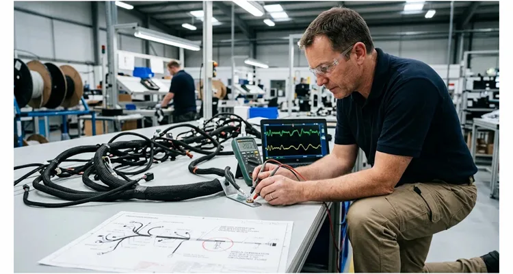
When a fleet calls me about a J1939 communication fault, the complaint is rarely “the bus is dead.” It is usually an intermittent SPN 639 or SPN 168, a U-code that clears after the truck sits overnight, or an ECU that drops off the bus only when the alternator is loaded and the engine is warm — the same pattern we see in intermittent J1939 faults that appear around 1800 rpm. A technician swaps the terminating resistor, the fault disappears for three weeks, then comes back.
I have traced enough of these failures back to the harness that I no longer treat alternator ripple and common-mode noise as background electrical “noise.” They are measurable, supplier-controlled characteristics. If your J1939 harness supplier cannot explain how they control them at cable selection, shield termination, and end-of-line test, you are buying a harness that will pass PPAP and fail in the field.
What follows is the audit sequence I use when a supplier claims capability in J1939 physical-layer harnesses for charging-system-adjacent circuits. It is not a generic supplier scorecard. It is a focused technical audit of the two failure modes that alternator ripple and common-mode current expose in a J1939 backbone. In our factory, this is also the sequence we expect a customer’s supplier-quality engineer to run on us.
Start with the ripple number the supplier is designing against
Ask the supplier’s engineering lead one question early: “What peak-to-peak AC ripple amplitude does your J1939 backbone design assume at the alternator B+ node, and over what frequency band?”
If the answer is a number without a frequency band and a test level attached, the number has no audit value. ISO 16750-2 describes superimposed AC ripple on the alternator output swept from 50 Hz to 25 kHz, with peak-to-peak amplitudes of 1 V, 2 V, or 4 V selected by severity level, not by feel. Some OEM standards push the upper sweep frequency higher and vary amplitude based on module location relative to the alternator and battery. Commercial fleet guidance commonly treats 400 mV AC as a maximum allowable threshold, with 500 mV AC as the absolute OEM upper limit, but that is a screening number for alternator health, not a harness design target.
A credible J1939 harness supplier will ask you for the OEM alternator specification for J1939 ripple coupling before quoting shield coverage or drain-wire construction. If they are quoting a J1939 harness for a charging-adjacent circuit without asking where the harness runs relative to the alternator output and the battery return, the quote is incomplete.
The shield termination is where common-mode control is won or lost
SAE J1939-11 defines a shielded twisted pair with a characteristic impedance of 120 Ω, and the shield is brought out as a dedicated CAN_SHLD connection. The standard is explicit that the shield should be terminated at a central point of least electrical noise, not at every connector shell.
In an alternator-adjacent harness, “least electrical noise” is a physical location, not a concept. It usually means the shield drain is grounded at a point on the chassis that is not sharing return current with the alternator charging path or the starter ground. The common-mode current induced on the cable shield by the alternator’s magnetic field has to be given a low-impedance path to chassis at one defined point.
Clamp the drain at both the engine-side bulkhead and the cab-side bulkhead and the continuity test will look better, not worse — lower resistance, clean beep. Then load the alternator and watch the same assembly. The chassis potential difference between the two clamps drives a current on the shield whose frequency content lines up with the ripple fundamental and its harmonics. What shows up on the pair is not a shield failure you can see on a differential probe; it is a common-mode component that appears as bit errors in the BCI monitor. This is the same mechanism behind common-mode voltage on J1939 that kills communication.
What the shield evidence has to prove on the finished assembly
“We use shielded cable” does not produce evidence in an audit. What produces evidence is where the drain is specified to land on the drawing, and whether that point shares a current path with the alternator return.
When you ask for the surface transfer impedance report, treat 225 mΩ/m as the pass/fail line on a finished assembly, not as a design target. The number only means something if the report covers the crimp and the connector interface, not just the raw cable drum. A supplier who hands you a cable-drum report and calls it shield validation has validated the extruder, not the termination.
The same logic applies to the twisted pair itself. After you measure capacitance on the finished assembly, multiply the datasheet’s pF/m by the cut length and add the termination-zone allowance you have established from known-good builds. If the reading sits above that window, the foil fold-back or the stripping process is bridging the shield. The 110 pF/m figure is the cable limit; the audit question is whether the finished J1939 harness assembly still sits inside the window that limit implies. This is a process-control issue, and it shows up in the crimp cross-section and the post-crimp electrical test, not in the incoming cable certificate. A finished assembly that sits above that window is a cable-asymmetry problem, and a 12 percent mismatch is enough to raise common-mode noise.
Common-mode current on trucks is not a passenger-car problem
When a supplier shows you a BCI report, check the injection level before you read the pass column. Truck and bus programs run at 114 dBμA, which is 500 mA of common-mode current; a passenger-car report at 106 dBμA, or 200 mA, is testing a different harness. A supplier who benchmarks common-mode immunity against the lower level is under-testing by a factor of two and a half in current terms. The frequency content is not arbitrary — it is J1939 common-mode noise following alternator ripple frequency.
When you audit, ask for the BCI test setup photographs, the injection probe placement relative to the alternator output cable, and the monitoring criterion used during injection. A harness that “passes BCI” with the DUT powered from a clean bench supply is not the same as a harness tested with the alternator ripple superimposed on the supply.
The physical construction choices that affect this are not exotic. They are AWG selection, pair twist consistency, shield coverage, and drain-wire gauge. SAE J1939-11 cable is commonly available in 18 AWG and 20 AWG conductor sizes, with drain wires in the 20 AWG range. Deutsch DT-series connectors used on truck and bus J1939 backbones accept size 16 contacts and 14–20 AWG wire. If the supplier substitutes a 20 AWG conductor where the drawing calls for 18 AWG to save cost, the IR drop changes, but more importantly the shield-to-conductor geometry and the drain-wire current capacity change. That is a deviation that should be caught at first-article inspection, not at a warranty review.
The audit sequence that separates capable suppliers from catalog assemblers
I run the J1939 harness supplier audit in four stages, in this order, because each stage produces evidence that the next stage depends on. The point of the sequence is not to collect four checklists. The point is that a miss at one stage makes the evidence at the next stage uninterpretable. If you need a short pre-audit question set to send before the on-site visit, start with these J1939 harness supplier qualification questions.
Stage one: drawing and cable specification review in a J1939 harness supplier audit
Before visiting the floor, ask for the customer drawing, the cable datasheet, and the shield termination detail. Verify that the cable datasheet states impedance at 1 MHz, conductor-to-shield capacitance, and surface transfer impedance. A cable datasheet that lists only “shielded” without electrical parameters is not a J1939-11 cable datasheet, and the rest of the audit has nothing to anchor to.
Stage two: process walk on shield preparation and drain crimp for J1939 harness suppliers
Watch an operator terminate a shield. Look at the foil fold-back distance, the drain-wire crimp height, and whether the crimp tool has a pull-force monitor. SAE J1939/11 splice guidance calls for removing the foil shield to within 2 mm of the cable jacket and stripping data wires to 7 mm ± 0.8 mm. These are small dimensions, and they are exactly where a supplier’s process discipline becomes visible.
If you see no strip-length gauge at stage two, do not wait for stage three data to draw a conclusion. Foil fold-back inside 2 mm without a gauge produces lot-to-lot capacitance scatter, not a clean fail — most units pass, a few read high, and the scatter gets misattributed to cable incoming variation. If the operator is working without a strip-length gauge or a documented crimp setup sheet, the process is not controlled, and the EOL numbers in stage three will show a distribution you cannot explain.
Stage three: electrical evidence on the finished J1939 harness assembly
Ask for 100% continuity and shield-integrity test records, not a sampling plan. The shield path should be tested for continuity from the designated grounding point to the far-end drain, with a resistance limit tied to the surface transfer impedance requirement on the finished assembly. If the supplier’s end-of-line tester does not include a shield-to-conductor isolation check, they are not catching foil bridging or drain-wire strand escape, and the stage two process walk is the only place that defect can still be found.
Stage four: validation evidence tied to the charging-adjacent J1939 circuit
This is where PPAP Level 3 documentation for OBD cable assemblies often thins out. A harness PPAP package should include the crimp pull-force studies, dimensional results, and electrical test evidence for the circuits that carry the J1939 pair and the shield drain. For an alternator-adjacent harness, the PPAP should also include a BCI report at the truck-level severity, or at minimum a documented test plan showing the injection point, current level, and pass/fail criterion. A PSW signature without that evidence is an administrative approval, not a technical one.
What the supplier’s quality system has to look like underneath the harness
The harness is a build-to-print assembly, but the failure modes are process-driven. That is why the quality system matters in this specific audit, not as a checkbox but as the mechanism that keeps shield termination and crimp geometry from drifting between lots.
A supplier holding IATF 16949 cable assembly traceability and ISO 9001 is operating under a documented process-control framework that requires crimp validation, traceability, and change management before shipment. In practical audit terms, that means the supplier can show you the PFMEA for the shield termination step, the control plan for the drain crimp, and the reaction plan if the pull-force monitor alarms. ISO 14001 environmental management certification and RoHS compliance matter here because the cable jacket and connector materials are part of the same build, and a material substitution under cost pressure can change the dielectric properties of the pair.
Why storage and acclimation matter in a J1939 harness supplier audit
J1939 cable capacitance and impedance are defined at 20°C reference conditions. If cable goes from a humidity-uncontrolled rack straight to the cut-and-strip line, the jacket and dielectric dimensions carry the storage environment’s lag into the stripping station. Strip length tolerances sit in the ±0.8 mm range, and material state changes eat into that tolerance.
You do not need to measure warehouse temperature and humidity during the audit. You need to ask one question: is there an acclimation step between goods receipt and the line, and can the acclimation record be tied to the lot? A factory running 5S and a climate-controlled warehouse will answer that with a record. A factory that stores cable on an open rack will answer with a policy statement.
What a real process history sounds like in a J1939 harness supplier audit
The 20-plus-year direct-factory experience signal is only useful if it shows up in the process detail. Ask a question specific enough that only a factory that has actually built these harnesses can answer it: the last time shield foil bridged after stripping, did the reaction plan stop the line or sort the lot? Was the sort criterion capacitance or visual? If the supplier can name the numeric window on the sort criterion, the experience is real. If the answer is “we would inspect it,” the experience is still at the policy level.
A factory that has been building J1939 harnesses long enough will have a specific answer: a crimp tooling change, a strip-length gauge addition, a foil fold-back fixture. That specificity is what you are auditing for, not the number of years on the certificate.
The comparison that matters: two harness builds, same drawing, different field behavior
| Audit checkpoint | Capable J1939 supplier | Catalog assembler |
| Ripple design input | Requests OEM conducted-ripple profile and BCI level before quoting | Applies a generic “0.5 V” rule or no stated ripple assumption |
| Shield termination | Single-point chassis ground documented on the drawing, drain crimp with pull-force monitor | Shield pigtail to nearest connector shell, no grounding point callout |
| Cable evidence | Datasheet includes 120 Ω ±10% at 1 MHz, ≤110 pF/m conductor-to-shield, ≤225 mΩ/m transfer impedance | Datasheet says “shielded twisted pair” with no electrical parameters |
| BCI validation | Truck-level 114 dBμA test report with alternator ripple superimposed | Passenger-car 106 dBμA bench test, or no BCI evidence |
| End-of-line test | 100% shield continuity and shield-to-conductor isolation on every unit | Sampling plan, continuity only on signal pair |
| Validation evidence tied to the charging-adjacent circuit | Crimp studies, dimensional report, BCI report, PSW tied to the alternator-adjacent circuit | PSW signed, crimp data missing, test reports from a different part number |
| Process control | PFMEA and control plan for shield preparation, reaction plan on pull-force alarm | Work instruction only, no PFMEA for the shield step |
How to confirm the fix worked before you release the supplier
Do not accept a supplier’s internal test report as the final confirmation. Build a small validation lot — ten to twenty assemblies from the production process, not hand-built samples — and run three checks.
- Measure shield-to-conductor capacitance on the finished assembly and compare it to the calculated value from the cable datasheet and the cut length. A finished assembly that reads significantly higher than the calculated value has a termination or stripping defect that is bridging the shield.
- Run a BCI test at the truck-level common-mode current with the DUT powered through a supply that has the OEM ripple profile superimposed. Monitor the J1939 differential signal for bit errors and the ECU for bus-off events. A harness that passes with a clean bench supply and fails with the ripple superimposed has a common-mode rejection problem that the bench test masked.
- Put the validation lot through a thermal and vibration screen that represents the engine-adjacent environment, then repeat the shield continuity and capacitance measurements. The failure mode I see most often after environmental exposure is a drain-wire crimp that passed pull-force at room temperature but relaxes after thermal cycling — the same mechanism behind crimp resistance drift of 3.2 milliohm and J1939 ground offset. If the post-screen capacitance shifts by more than a few percent, the termination is not stable.
If you are auditing a supplier for a program where the J1939 backbone runs near the alternator output or shares a bulkhead connector with charging circuits, and you want a second set of eyes on the drawing and the PPAP evidence before you release the tooling, the engineering team at our factory can review the shield termination scheme and the test plan with you. We build J1939 harnesses under IATF 16949 and ISO 9001 with a four-step inspection sequence that includes shield integrity and crimp pull-force on every lot, and we quote OEM customization — logo, length, color, AWG — against the drawing, not against a catalog page. You can reach the engineering desk through WhatsApp here: https://api.whatsapp.com/send/?phone=8617307168662&text=Need+Help%3F+Chat+linda+WhatsAPP&type=phone_number&app_absent=0. If you prefer to send drawings and the OEM ripple/BCI specification first, the contact page is here: https://obd-cable.com/contact/.
FAQ
What ripple amplitude should a J1939 harness supplier design against?
There is no single harness-level ripple number. The design input is the OEM’s conducted-ripple profile, commonly based on ISO 16750-2 with peak-to-peak amplitudes of 1 V, 2 V, or 4 V swept from 50 Hz to 25 kHz depending on severity. Commercial fleet screening often uses 400–500 mV AC as an alternator-health threshold, but that is not a harness design target.
Is 114 dBμA really the BCI level for trucks?
Yes. Truck and bus BCI requirements are commonly specified at 114 dBμA, equivalent to 500 mA of common-mode current, compared with 106 dBμA (200 mA) for passenger-car-level testing. A supplier quoting passenger-car BCI evidence for a truck J1939 harness is under-testing the assembly.
Should the J1939 shield be grounded at both ends?
SAE J1939-11 guidance calls for the shield to be connected at the point of least electrical noise, as close to the center of the bus as possible. In practice, a single-point chassis ground is used to avoid driving alternator return current onto the shield. The exact grounding point should be documented on the customer drawing.
What cable parameters belong on the datasheet for a J1939-11 harness?
At minimum: characteristic impedance of 120 Ω ±10% at 1 MHz, conductor-to-shield capacitance of 110 pF/m maximum, and shield effectiveness of 225 mΩ/m maximum surface transfer impedance. A datasheet that omits these numbers cannot be used to verify that the cable meets J1939-11.
Can a 20 AWG conductor be substituted for 18 AWG in a J1939 backbone?
Not without engineering approval. SAE J1939-11 cable is available in both 18 AWG and 20 AWG, but the substitution changes IR drop, drain-wire current capacity, and the shield-to-conductor geometry. It is a deviation that should be captured at first-article inspection, not discovered in the field.
How do I judge whether a PPAP package is sufficient for an alternator-adjacent J1939 harness?
A PPAP package for an alternator-adjacent J1939 harness is sufficient only if the BCI evidence shows the injection point relative to the alternator output cable and the DUT is powered with the ripple profile superimposed. Crimp pull-force studies, dimensional results, and electrical test evidence for the signal pair and shield path must be tied to the same part number and revision as the PSW.
Why does shield termination process control matter more than the raw cable certificate?
The raw cable certificate proves the cable left the extruder within specification. The finished assembly’s shield effectiveness depends on how the foil was folded back, how the drain wire was crimped, and whether the pair geometry survived stripping. A process without a strip-length gauge or a monitored drain crimp can turn a compliant cable into a non-compliant assembly.
How do I verify the fix after a supplier changes their shield termination process?
Build a validation lot from the production process, measure shield-to-conductor capacitance against the calculated value, run BCI with the OEM ripple superimposed, then repeat the capacitance and continuity measurements after thermal cycling and vibration. A termination that shifts capacitance after environmental exposure is not stable.
Does ISO 9001 alone qualify a supplier for J1939 harnesses with common-mode requirements?
ISO 9001 provides a quality management framework, but IATF 16949 is the automotive-specific system that requires PPAP, crimp validation, and change management for harness programs. For a charging-adjacent J1939 harness, I would treat IATF 16949 as the baseline and the BCI/ripple evidence as the technical differentiator.
What is the most common shield termination defect you see in supplier audits?
The drain wire crimped to the connector shell instead of routed to a documented single-point chassis ground. It looks electrically continuous on a bench continuity test, but it drives alternator-return-driven common-mode current onto the pair when the alternator is under load. The second most common is foil fold-back that leaves a fragment bridging the shield to the conductor after stripping. Both are process-control defects, not cable defects.
