

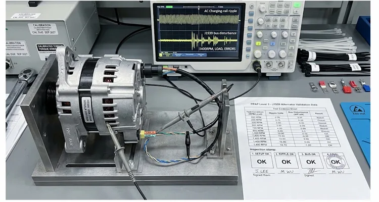
A 24 V alternator passes the battery-terminal ripple gate at 180 mV peak-to-peak. The PSW is signed. Eighteen months later, the OEM’s warranty database shows a cluster of J1939 communication DTCs on units built in the same production window. The ripple was never the variable that failed; the coupling path was. What we see repeatedly in PPAP Level 3 packages for J1939 alternators is not a noisy alternator. It is evidence collected at a node that cannot predict what the transceiver sees.
This is a test-method gap, not a component-quality gap. A PPAP Level 3 submission is the default complete-data package in automotive production part approval, as defined under the AIAG PPAP framework. Level 3 is the complete-data package: PSW, samples, dimensional and material results, capability, FMEA, control plan, MSA. None of those elements is designed to catch a coupling-path defect. A dimensional report can be perfect, a PFMEA can list “CAN communication fault” as a downstream effect, and the package still passes without a single measurement taken at the transceiver reference plane.
The gap is structural: the eighteen-element template never asks where the probe reference sits, so a supplier can complete every line item without ever measuring at the receiver reference plane. For an alternator with a J1939 interface, the ripple-to-bus coupling test evidence is the element most often thin, borrowed from a generic EMC report, or missing entirely. What follows is what that evidence should actually contain — from a bench that has run this test on 24 V and 12 V heavy-duty platforms long enough to know where the quiet failures hide, and from a factory workflow that has to make the resulting evidence traceable under OEM alternator specification for J1939 ripple coupling requirements.
The Failure Mode Nobody Puts in the DFMEA
A healthy alternator leaves a small residual AC component on the charging rail. The 0.25–0.50 V AC RMS figure that circulates in charging-system diagnostics was established for 12 V platforms under accessory-load conditions. A 24 V alternator regulating at 28 V does not inherit that limit by arithmetic scaling; the transceiver’s input threshold margin and the common-mode range at the actual system voltage determine what the coupling path can tolerate. The conventional field limit is useful as a starting point, but it is not a coupling criterion.
The commonly cited 400 mV peak-to-peak figure, measured across the charging rail at 50–300 Hz, is a useful first-order screen for diode-bridge health. It is not a coupling criterion. On our bench, a 24 V unit passing at 180 mV still produced frame errors once the shield drain was routed parallel to B+ over 30 cm. That observation is the whole reason this test exists. The number is a useful anchor. It is not a transfer function.
A 24 V alternator can pass the battery-terminal ripple check at 180 mV peak-to-peak and still corrupt J1939 frames, because the coupling mechanism is not the charging rail voltage itself. It is the common-mode voltage that develops across the alternator housing, the engine block, and the chassis ground reference when high di/dt currents flow through the rectifier bridge and stator return paths. That common-mode voltage drives current through the cable shield, through the CAN transceiver’s ground reference, and into the J1939 differential pair as a common-mode disturbance that the transceiver’s input stage rejects imperfectly. This is the mechanism behind the J1939 common-mode noise from alternator ripple frequency pattern we screen for before a PPAP sample ever reaches the OEM. The differential signaling that CAN relies on is designed to reject exactly this kind of electrical noise, but rejection has finite limits that a battery-terminal trace does not reveal.
Why Battery-Terminal Ripple Is the Wrong Measurement Point
The battery-terminal ripple measurement captures the differential voltage between B+ and battery negative. It tells you the alternator’s output quality. It tells you nothing about the impedance between the alternator return path and the J1939 cable’s reference plane. On a test bench, those two grounds are often bonded at a single star point with a short, thick strap. In the vehicle, the return current from a 200 A alternator flows through the engine block, the frame rails, and multiple body grounds — a distributed network with inductive and resistive terms that a bench star point does not replicate.
A PPAP Level 3 coupling test that only repeats the battery-terminal ripple measurement is a measurement of the wrong quantity at the wrong node. The OEM’s validation engineer will see the gap immediately, and the PSW will sit in “interim approval” until the missing evidence arrives. The same logic explains why a measurement taken without a differential probe can look clean on a bench while the receiver still sees a disturbance.
What the Coupling Test Bench Must Actually Measure
The test has two simultaneous acquisition channels, not one.
Channel A — the aggressor. Measure alternator output ripple at the B+ stud and alternator housing with AC coupling, with the probe reference clipped directly to the bare aluminum housing rather than to a remote battery negative. This establishes the source amplitude and frequency content under defined load and speed conditions.
Channel B — the victim. Measure the J1939 bus differentially at the point where the harness would connect to the first ECU or a representative bus load. A differential probe across CAN_H and CAN_L captures the signal that the transceiver actually sees. Critically, also measure the common-mode voltage on each line relative to the alternator housing reference. The difference between the differential disturbance and the common-mode disturbance is the transceiver’s effective common-mode rejection under real source impedance — and that rejection is frequency-dependent, degrading above a few hundred kilohertz.
The coupling path is the variable under test. It is determined by:
- Shield termination strategy: single-point at the ECU end, single-point at the alternator end, or both ends bonded. SAE J1939-11 specifies a shielded twisted pair physical layer for robust EMI immunity, but the shield termination practice is where OEMs diverge.
- The distance and routing between the alternator B+ cable and the J1939 twisted pair. A 20 cm parallel run with no separation is a different coupling geometry from a 5 cm orthogonal crossing.
- The impedance of the alternator return path to the J1939 cable’s reference point. This is the parameter the battery-terminal ripple test ignores entirely.
A coupling test that does not control these three variables is not a coupling test. It is a second ripple measurement with extra steps.
What the Shield Termination Variable Looks Like on a Loaded Bench
On a 24 V bench with the shield bonded only at the ECU end, we have seen the differential disturbance at a mid-bus node increase by a factor of three when the harness length moved from the minimum to the maximum of the PPAP drawing envelope — same alternator, same load point, same probe placement. The only variable was the parallel run length between B+ and the twisted pair. That is the kind of observation a coupling test is supposed to capture. It is not visible in a battery-terminal ripple trace, and it is not visible in a summary table that reports a single peak-to-peak number.
This is also where common-mode voltage on J1939 can kill communication without leaving a simple ripple number behind, and why cable asymmetry and common-mode noise belong in the same review as the alternator itself.
Test Conditions That Separate a Pass from a Paper Pass
The alternator must be exercised across the speed and load envelope, not at a single idle point. Ripple amplitude and frequency content change with rotor speed, electrical load, and regulator switching behavior. A test matrix that holds speed at 2,000 rpm and load at 50% will miss the resonance where the coupling path is most efficient.
A defensible PPAP Level 3 coupling test matrix includes at minimum:
| Test variable | Why it is in the matrix | Typical points for a 24 V heavy-duty alternator |
| Rotor speed | Ripple frequency scales with speed; coupling resonances appear at specific harmonics | 1,200 / 2,000 / 3,500 / 5,000 rpm |
| Electrical load | Diode conduction angle and di/dt change with load; light load can produce sharper transients | 10% / 50% / 90% of rated output |
| Battery state | A depleted battery loads the rail differently from a fully charged one; load-dump residual can bias the coupling path | Nominal battery emulated at 26.5 V, plus a low-impedance electronic load |
| Shield termination | The single largest variable in common-mode coupling | ECU-end only / alternator-end only / both ends |
| Harness length | Coupling efficiency increases with parallel run length | Minimum and maximum in the PPAP drawing envelope |
This is exactly why a single 2,000 rpm snapshot can miss the failures that happen on the road. When you sweep the matrix, specific rotational speeds will amplify the coupling path. We have seen this directly during field diagnostics for alternator ripple J1939 SPN 3644 at 1400 rpm, where a resonance at a specific low-speed engine harmonic pushed a previously “passing” harness assembly into a communication fault state. A defensible test matrix forces the alternator to reveal those resonances on the bench, not in the vehicle.
Setting the Guard Band Without Guessing
A transceiver’s differential input threshold is nominally around 0.5 V for a dominant bit decision, but the effective margin shrinks when common-mode voltage moves. A coupling test should document the measured differential disturbance in millivolts peak-to-peak and the measured common-mode excursion on each line, then show the arithmetic: differential signal amplitude at the receiver minus the worst-case disturbance amplitude must exceed the transceiver’s guaranteed threshold with margin.
If the bench cannot resolve the transceiver-level margin directly, a substitution load that replicates the input network of the target ECU family is acceptable — but the PPAP package must state what was substituted and why. A 120 Ω resistor across CAN_H and CAN_L terminates the line, but it does not replicate the input network of a transceiver. When we substitute a resistive load on the bench, we lose the common-mode rejection path that the real ECU input stage provides. The differential disturbance reading can look identical; the receiver-level margin is not.
Why a 120 Ω Resistor Is Not a Bus Load
That is why a coupling test report that cites “bus load = 120 Ω” without the input network values is not a substitute for a transceiver-referenced measurement. An OEM reviewer will accept a documented substitution. They will not accept an unlabelled resistor described as “bus load” when the receiver-level margin has not been characterized.
Where Suppliers Get This Wrong: Four Recurring Gaps
Gap one: using a 12 V ripple limit on a 24 V system. The 0.4 V peak-to-peak figure is widely quoted, but it originates in 12 V charging-system diagnostics. A 24 V alternator with a 28 V regulated output has a different absolute ripple tolerance relative to the transceiver supply. Scaling the limit by voltage alone is not engineering; the coupling path impedance and the transceiver’s common-mode range must be evaluated at the actual system voltage.
Gap two: measuring at the diagnostic connector with the vehicle harness in place. The diagnostic connector is convenient, but it is at the far end of the bus from the alternator. A disturbance that is benign at the diagnostic connector can be disruptive at an intermediate ECU whose ground reference sits closer to the alternator return current path. The coupling test must include at least one measurement point representative of a mid-bus node, not only the diagnostic access point.
Gap three: a single shield-termination configuration. If the PPAP drawing permits either single-point shield termination, the coupling test must demonstrate that both permitted configurations meet the bus disturbance criterion. A PPAP that tests one configuration and approves a drawing that allows the other is a latent field failure.
Gap four: no frequency-domain evidence. A time-domain peak-to-peak number is necessary but not sufficient. The coupling test should include a spectral plot of the common-mode disturbance and the differential disturbance, with the transceiver’s sensitivity curve overlaid or tabulated. This is the evidence that tells the OEM whether a future alternator variant with a different regulator switching frequency will remain inside the margin. Without it, the PPAP approval is valid only for the exact sample tested.
How a Factory Builds a PPAP Coupling Test That Survives OEM Review
The factories that pass this review on the first submission share a pattern. They do not treat the coupling test as a final inspection step bolted onto the end of the line. They treat it as a process-control parameter with traceability back to the materials and geometry that determine the coupling path.
At a direct factory with more than twenty years of harness assembly experience, the quality-system scope matters as much as the certificate. ISO 9001, ISO 14001 environmental management, IATF 16949, RoHS, CE, UL, and REACH are not badges to paste into a PPAP cover sheet; they define which procedures, calibration records, and corrective-action loops the coupling test sits inside.
The Evidence Chain Starts Before the Bench
The evidence chain for a coupling test starts before the alternator is mounted on the bench. The cable’s shield coverage, drain-wire construction, and twist pitch are recorded against the drawing. The alternator’s housing-to-bracket bond resistance is measured and logged. The bench ground reference impedance is characterized and documented. None of this is documentation for its own sake; each entry is a variable that moves the coupling path, and a number that cannot be traced back to a record cannot be defended in an OEM review.
A four-step quality inspection discipline — incoming material, in-process crimp and shield termination, 100% electrical test on the finished assembly, and outgoing qualification sample retention — provides the traceability backbone. The 5S-managed, climate-controlled warehouse is not a slogan in this context; shield drain oxidation and jacket shrinkage change the coupling path. The RoHS-compliant full-plastic design and 100% tested finished assemblies are recorded in the same traceability system as the crimp height and shield drain length.
When an OEM asks why a particular PPAP sample showed a coupling resonance at a specific speed, the factory can trace that sample’s shield drain length and crimp height to the in-process record. That is the difference between a PPAP package that closes and a PPAP package that generates a corrective action request, and it is why IATF 16949 cable assembly traceability has to be read as a test-evidence issue, not a certificate issue. The same discipline sits under PPAP Level 3 documentation for OBD cable assemblies when the product family and the test activity are both inside the certified scope, and it is the same quality system behind our IATF 16949 certification milestone.
For OEM customization programs that require logo, brand, length, color, and AWG customization, the coupling test must be repeated or at least re-validated for each configuration that changes a coupling-relevant variable. A length change alters the parallel run geometry. An AWG change alters the source impedance and the shield drain current capacity. A color change of the jacket is coupling-neutral; a change in shield material or coverage is not. A supplier that applies the same coupling test report across all configurations without a documented similarity analysis is telling the OEM that the test is a formality.
A Practical Supplier Screening Sequence for PPAP Level 3 Coupling Evidence
When evaluating a harness or cable assembly supplier for a J1939 alternator program, the PPAP package arrives as a document set. The coupling evidence is buried inside it, and its quality is not visible from the table of contents. The following supplier screening sequence separates a supplier who understands the physics from one who is repackaging a generic EMC report. It also complements the broader J1939 harness supplier qualification questions that belong in the same audit file.
The Six-Question Audit for Coupling Evidence
- Ask for the test setup photograph and the ground-reference diagram before the numerical results. A supplier who leads with peak-to-peak numbers without showing where the probe references were placed is a supplier who has not thought about the coupling path. The ground-reference diagram reveals whether the bench star point was chosen for convenience or designed to represent the vehicle return network.
- Request the raw Channel B differential and common-mode traces, not only the summary table. The summary table can be generated from a single trace. The raw traces show whether the measurement was repeated across the test matrix or extrapolated from one condition.
- Ask which shield-termination configuration was tested and whether the PPAP drawing permits any other. If the answer is “we tested the standard configuration” without a drawing cross-reference, the evidence does not cover the production envelope.
- Verify that the transceiver substitution, if used, is documented with its input network values and threshold specification. An unlabelled 120 Ω resistor is a red flag. A documented active load that replicates the target ECU’s input characteristics is acceptable.
- Confirm that the factory’s IATF 16949 scope explicitly includes the product family and the test activity. A quality certificate with a scope that covers “wire harness assembly” but not “electrical performance testing” leaves the PPAP evidence outside the certified quality system. The scope matters as much as the certificate.
- Ask how a change in alternator regulator switching frequency would be handled. A supplier who says “we would re-test” is acceptable. A supplier who says “the existing report covers it” is telling you the report is a snapshot, not a process control.
Frequently Asked Questions
Does PPAP Level 3 explicitly require a ripple-to-bus coupling test?
PPAP Level 3 requires the complete supporting data package for the part and process, but the specific test content is defined by the OEM’s engineering specification and the customer-specific PPAP requirements. A ripple-to-bus coupling test is not named as a universal PPAP element. It becomes a required piece of evidence when the OEM’s J1939 interface specification or EMC validation plan calls for it — and for alternators with a bus interface, that call is increasingly explicit because battery-terminal ripple alone does not predict communication integrity.
What is the difference between a ripple test and a ripple-to-bus coupling test?
A ripple test measures the AC content on the charging rail, typically at the battery terminals or the alternator B+ stud. A ripple-to-bus coupling test measures the disturbance that appears on the J1939 differential pair and the common-mode voltage on each bus line when the alternator is producing ripple under defined load and speed conditions. The coupling test includes the ripple source but adds the transfer path — shield termination, harness routing, and ground reference impedance — as variables under measurement.
Can I use a 0.4 V peak-to-peak limit as the coupling test pass criterion?
No. The 0.4 V peak-to-peak figure is a charging-rail ripple limit associated with rectifier diode health. The coupling test criterion is a receiver-level margin, expressed in millivolts relative to the transceiver’s input threshold under the measured common-mode excursion. Using the charging-rail limit as the coupling criterion conflates source amplitude with delivered disturbance and will pass assemblies that corrupt bus communication.
Why does shield termination change the coupling result?
The shield provides a return path for common-mode current. If the shield is terminated at only one end, the common-mode current must find another return path — often through the transceiver ground reference, which converts common-mode voltage into a differential disturbance at the receiver input. Terminating both ends can reduce the common-mode excursion but may introduce ground-loop current. The coupling test must evaluate the specific shield termination strategy permitted by the PPAP drawing, not assume that one strategy is universally superior.
What speed and load points should be in the test matrix?
At minimum, the test matrix should span the low, mid, and high rotor-speed range of the alternator’s operating envelope and the light, medium, and heavy electrical-load range. Ripple frequency and di/dt are speed- and load-dependent, and coupling resonances can appear at specific harmonics that are absent at a single mid-point condition. A single-speed, single-load test is a screening check, not a PPAP-grade coupling validation.
Does the test require a real ECU on the bus, or is a resistive load acceptable?
A real ECU or a documented active load that replicates the target transceiver’s input network is preferable because the transceiver’s common-mode rejection and input threshold behavior under disturbance are part of the margin calculation. A resistive load can characterize the cable and coupling path but cannot demonstrate receiver-level immunity. If a resistive load is used, the PPAP package must state the substitution and its limitations explicitly.
How does a factory’s IATF 16949 certification relate to the coupling test evidence?
IATF 16949 certification confirms that the factory’s quality management system has been audited against automotive industry requirements. It does not automatically validate a specific test method. The relevant question is whether the coupling test procedure, equipment calibration, and personnel competence fall within the certified scope and are subject to the factory’s internal audit and corrective-action processes. A supplier who can trace the coupling test back to a controlled procedure under the IATF 16949 scope is providing stronger evidence than one who presents a certificate and a separate lab report.
Can the coupling test be waived if the alternator passes CISPR 25 or ISO 7637?
No. CISPR 25 limits what the alternator radiates and conducts onto the harness; ISO 7637 limits what the harness survives. Neither test places a probe at the transceiver input while the alternator is loaded and the shield is terminated per the production drawing. The quantity that falls between them — continuous common-mode disturbance delivered to the transceiver reference plane under loaded operating conditions — is exactly the quantity a ripple-to-bus coupling test exists to measure. The tests are complementary, not substitutable.
What should be done if a production sample fails the coupling criterion but passes the battery-terminal ripple limit?
That result is diagnostic, not contradictory. It points to the coupling path — shield termination, harness routing, ground reference impedance — rather than the alternator output quality. The corrective action should target the path variables, not automatically tighten the alternator ripple specification. A supplier who responds by screening alternators for lower ripple without investigating the path is treating the symptom.
How does OEM customization of cable length or shield construction affect an existing PPAP coupling approval?
Any change that alters the parallel run geometry, the shield drain impedance, or the common-mode return path requires either a re-test or a documented similarity analysis with engineering justification. A length change within a validated envelope may be covered by similarity; a shield coverage or drain-wire construction change generally is not. The PPAP package should define which configuration variables are coupling-critical and which are not, so the OEM can evaluate future variants without re-opening the full validation.
Closing: The Evidence That Closes the PSW
The OEM engineer reviewing a PPAP Level 3 package for a J1939 alternator is not looking for a perfect number. They are looking for evidence that the supplier understands which number matters and why. A battery-terminal ripple trace with a green checkmark answers a question that was settled twenty years ago. The unresolved question is how that ripple behaves once it reaches the bus — and whether the production process, across every configuration the drawing permits, keeps that behavior inside the receiver-level margin.
If your program is preparing a PPAP Level 3 submission for a J1939 alternator harness or cable assembly and the coupling evidence is the open item, the fastest path forward is a direct conversation with the engineering team that builds the test setup, not a sales inbox. The WhatsApp line below reaches an application engineer who can review your existing test data against the test matrix and guard-band logic described here. For drawing-level OEM customization — shield termination, length, AWG, connector family, or branding — the contact page routes to the same engineering group.
WhatsApp engineering support: https://api.whatsapp.com/send/?phone=8617307168662&text=Need+Help%3F+Chat+linda+WhatsAPP&type=phone_number&app_absent=0
Contact page for OEM customization and PPAP documentation review: https://obd-cable.com/contact/
