

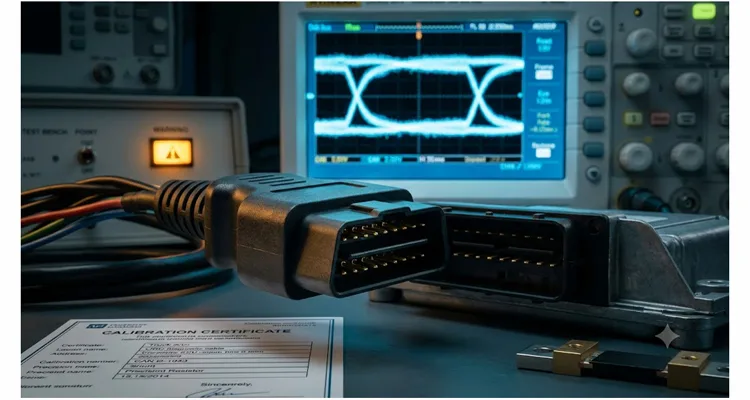
It was a Thursday night in late October when the call came in. The engineering director on the other end had been up for thirty hours straight. His company was seven days from shipping their first fleet telematics gateway to a Class 8 truck OEM. Every bench test had passed. But when the production-intent OBD cable assemblies went on the real vehicles, the fuel consumption data read 8.3% higher than the reference instrumentation. Not a bit-flip error. Not a firmware parsing bug. A clean, repeatable, analog offset that scaled with engine load. He told me, “The cable supplier swore their harnesses were 100% tested. Continuity, pinout, everything perfect. What do we do?”
They had walked straight into a calibration mismatch without realizing the cable had become an uncalibrated component in the measurement loop. That launch slipped six weeks and burned over one hundred and forty thousand dollars in expedited rework, air freight, and penalty clauses. In the years since, I’ve pulled the same root cause out of agricultural ISOBUS tools, electric vehicle DBC-based diagnostic adapters, and motorcycle scan cables. After dissecting over two dozen delayed product launches, I can tell you this: the fault is rarely the ECU itself. It’s the assumption, buried in the procurement package, that an OBD cable assembly is just a commodity wire harness. It isn’t. When the cable becomes part of the measurement loop, its electrical fingerprint either aligns with the ECU’s calibration assumptions or it silently destroys data integrity.
What follows is a signal-level dissection of calibration mismatch, three integration failures I’ve personally untangled, and a procurement-ready specification list to stop this problem before it ever reaches a pilot build.
The Phantom in the Machine: What Calibration Mismatch Actually Is
Every production ECU that broadcasts parameter values on a vehicle network does so based on a set of electrical assumptions baked in during calibration. The engineering team had a specific external circuit in mind: a known shunt resistance for current sensing, a precise voltage divider for K-line threshold detection, a defined split-termination impedance for CAN bus, and an expected parasitic capacitance on the signal lines. Those numbers are burned into the control strategy. If the external harness alters any of them, the ECU still dutifully transmits data — but the physical meaning of those bits has drifted, creating an ECU calibration error that no bus analyzer will flag.
Take a J1939 engine that reports fuel rate via the LFE (Liquid Fuel Economy) PGN. The ECU measures injector pulse width and common rail pressure, but it also relies on a current-sense resistor in the return path of the fuel actuator driver to validate actual flow. Some heavy-duty ECUs route that sense line through the diagnostic connector, expecting a precision 0.1 Ω shunt with a temperature coefficient under ±25 ppm/°C inside the vehicle-side harness. If the aftermarket OBD cable replaces or parallels that shunt with a 0.12 Ω resistor molded into its overmold — because the cable supplier chose a commodity sense resistor — the ECU’s internal calibration constant is now wrong by 20%. The digital payload on the CAN bus will look perfect. No CRC errors, no DTCs. Only when you compare logged values against a calibrated flow meter does the lie become visible. This is a classic OBD cable calibration failure: the bits are clean, but the physics is lying. We’ve seen this exact offset pattern in fleet aftermarket telematics installations where the procurement team sourced cables from a supplier that treated the shunt as a generic commodity part.
How a 0.7 V Voltage Divider Drift Breaks K-Line Handshakes
The identical physics applies to voltage-based analog inputs used on legacy ISO 9141-2 K-line or J1850 VPW interfaces. The ECU monitors the idle voltage on the K-line to determine if a diagnostic tool is present. A voltage divider inside the connector shell that drifts the threshold by even 0.7 V can cause the ECU to refuse a handshake, or worse, intermittently enter a diagnostic session only when the engine bay cools down — a K-line voltage divider drift that leaves no trace in the error log.
There’s no mystery here — apply Kirchhoff’s laws and put a differential probe on the line, and the root cause shows itself. But the gap between “continuity tested” and “calibration verified” is where projects bleed schedule and credibility.
Three Integration Nightmares from the Field
Case 1: The 12% Fuel Offset That Almost Killed a Fleet Trial
A telematics provider had signed a contract to equip four hundred refuse trucks with data loggers that captured fuel use, idle time, and DPF regen cycles. Their hardware used a third-party J1939 Y-cable that split the vehicle’s diagnostic connector. During the pilot on six trucks, the data showed fuel consumption numbers that the fleet manager refused to accept; his monthly fuel invoices proved the telematics data was off by roughly twelve percent.
I was brought in after the ECM firmware team had already wasted a week chasing a phantom bug. We isolated the cable and measured the shunt resistor inside the molded Y-junction that tapped the vehicle’s power-train CAN. The specification required 120 Ω terminator resistors at the two ends of the bus, but the Y-cable introduced a hidden third termination of 98 Ω — a parallel combination of two incorrectly chosen resistors in the tap. That CAN bus impedance mismatch shifted the recessive voltage level on CAN high and low just enough to cause a consistent amplitude compression on the dominant bits. The CAN transceiver in the logger was interpreting borderline differential voltages, occasionally skewing the bit sample point and injecting a few dominant-to-recessive edge errors in every hundredth frame. The higher-layer protocol recovered the frame with no checksum error, but the payload occasionally read a stale buffer value that looked like a slight offset in averaged fuel rate. This is the same mechanism we unpack in our deep-dive on CAN bus termination misdiagnosis.
Fix: replace the Y-cable with one that isolates the bus using a high-impedance buffer circuit rather than a passive tap, and specify the exact split-termination topology in the cable print. The supplier’s “standard automotive-grade” cable turned out to be a copy of a passenger-car J1962 splitter never intended for heavy-duty CAN topologies. For tight engine bay installations where a right-angle connector is needed to avoid bending the harness, a properly engineered J1939 right-angle Y-splitter cable with correct termination values eliminates both the mechanical strain and the impedance mismatch in one assembly.
Case 2: Intermittent K-Line Handshake on a Motorcycle Diagnostic Tool
A diagnostic tool maker designed a ruggedized tablet for powersport dealerships. It communicated over ISO 14230 KWP2000 on a K-line. Prototype cables were hand-built by their own engineering lab using an adapter board; everything worked. For production, procurement sourced a molded OBD cable assembly from a new supplier at a lower piece price. First field units started failing to initialize the ECU on certain Honda and BMW motorcycle models — but only when the bike had been running for more than twenty minutes.
We traced the fault to the voltage divider that set the K-line receiver threshold. The lab cable had used 1% tolerance 10 kΩ and 15 kΩ resistors, establishing a clean transition near 60% of battery voltage. The production cable’s overmold encapsulated a resistor network with a thick-film printed element that drifted 4% when the connector shell heated up from engine bay convection. Above 55°C ambient, the threshold crept up to 68% of Vbatt. The ECU, which was calibrated to see a valid logic high above 65% Vbatt, began dropping the handshake. The worst part: the failure would vanish by the time the bike reached the service bay for troubleshooting — a textbook temperature-dependent K-line voltage divider drift.
That cost the tool maker seventy-eight thousand dollars in field-return logistics and nearly lost them their premium dealer channel. They ended up specifying precision thin-film resistors with a published temperature curve and requiring every cable batch to pass a thermal chamber cycling test on a reference ECU.
Case 3: CAN FD Bit Timing Collapse on an EV Battery Diagnostic Interface
A Tier-1 engineering services firm was building a battery state-of-health tool for a European EV platform that uses CAN FD at 5 Mbps on the OBD connector. The tool worked flawlessly on their bench with a 30 cm flying-lead harness. When they extended to a 3-meter production-length cable, the bit error rate shot up above 10⁻⁶, rendering the tool useless.
The issue was cable capacitance. Their bench harness had 32 pF/m; the production cable used a low-cost unshielded twisted pair with 55 pF/m. Combined with the ECU’s transceiver drive strength, that extra capacitance slowed the differential signal rise time from 18 ns to 29 ns. At 5 Mbps, the bit time is only 200 ns. The CAN FD controller’s secondary sample point, calibrated to the original rise-time profile, now sampled during the signal transition instead of the stable plateau. Result: persistent CRC delimiters errors and a controller that quickly entered bus-off state.
The engineering firm had assumed “CAN cable is CAN cable,” as many teams do until they hit a CAN FD bit timing collapse. The procurement team had no electrical specification in the purchase order beyond “3-meter OBD-II to pigtail, pin 6 and 14 CAN, 120 Ω termination.” No capacitance limit, no propagation delay skew number, no impedance tolerance. They learned to demand an S-parameter report and an eye-diagram mask compliance test at the intended data rate on every first-article submission. Had they known how to read the J1939 waveforms correctly, they would have spotted the rise-time degradation on the bench.
Root Cause Breakdown: Where Calibration Drift Hides
The table below maps the most frequent calibration mismatch types I encounter, along with the real-world triggers that set them off, their symptoms, and the vehicle networks where they cause the most damage.
| Mismatch Type | Root Cause | Real-World Trigger | Typical Symptom | Common Networks |
| Termination resistance deviation | Resistor value, placement, or tolerance wrong in the cable assembly | Y-cable with hidden parallel 98 Ω instead of isolated bus buffer (refuse truck case) | Intermittent CAN error frames, sporadic bus-off events | CAN 2.0B, CAN FD, J1939 |
| Shunt resistance offset | Current-sense resistor in cable not matched to ECU calibration constant | Commodity 0.12 Ω shunt substituted for 0.1 Ω precision shunt in overmold | Fuel rate, current, or load parameter offset by 3–15% | J1939, ISO 15765 with analog sense pins |
| Voltage divider threshold drift | K/L-line divider resistors with poor TCR or wrong ratio | Thick-film printed resistor network drifting 4% above 55°C (motorcycle diagnostic tool case) | No communication, intermittent wake-up, missing ECU during scan | ISO 9141-2, ISO 14230, J1850 VPW |
| Added bus capacitance | High-capacitance wire, long untwisted leads, metallic overmold | Unshielded 55 pF/m twisted pair substituted for spec 32 pF/m cable on a 3 m run (EV battery tool case) | Bit timing violations, CRC errors, signal amplitude drop at high baud rates | CAN FD, SWCAN, FlexRay |
| Contact resistance calibration | Plating mismatch (tin vs. gold) on terminal pins increasing mated resistance | Tin-plated terminals on Vbatt/ground developing oxide layer in high-humidity fleet environment | Voltage drop on VBatt or ground pin shifting ADC reference in the tool | All protocols that use pin 16 (VBatt) and pin 4/5 (GND) as reference |
| Propagation delay skew | Unequal length or dielectric constant in twisted pair inside the cable | Unequal twist pitch in twisted pair of a long CAN FD cable | Asymmetric differential signal, increased EMI susceptibility, ACK slot errors | CAN FD, high-speed CAN |
The pattern across every failure mode is the same: the cable is an active circuit element, not a passive pass-through. When procurement treats it as a simple accessory, the risk stays invisible until DV/PV testing — or worse, until field deployment.
What Procurement Teams Can Demand — A Technical Specification That Works
If you’re a procurement manager or a supplier quality engineer writing an RFQ for OBD cable assemblies that will be integrated into test equipment, telematics units, or diagnostic tools, move beyond the pinout drawing. From two decades of troubleshooting these failures, here is the minimum specification set I recommend writing directly into your technical requirements document. They sound demanding. That’s the point. Suppliers who can’t answer them are the ones who cause the nightmares.
- 1. Shunt resistor accuracy and temperature coefficient. If your cable uses any in-line current sensing (often on J1939 pin assignments or auxiliary analog inputs), specify the exact resistor value, tolerance (e.g., ±0.1%), power rating, and TCR (e.g., ±25 ppm/°C over -40 to +125°C). Require a four-wire Kelvin resistance measurement report per lot.
- 2. Termination network topology and tolerance. Do not just write “120 Ω termination.” Define whether it’s a single-ended termination, a split termination with capacitor, and which pins are terminated. State the tolerance: ±1% is standard for CAN FD at high data rates. Include the common-mode choke specification if your tool uses it. The difference between a correct split termination and a simple resistor is often the difference between a quiet bus and a 23-cent component causing fleet downtime.
- 3. Differential impedance and capacitance. For CAN and CAN FD, call out a differential impedance of 120 Ω ±10% and maximum inter-wire capacitance of 45 pF/m. For longer cable runs, demand a TDR (Time Domain Reflectometer) plot showing consistent impedance along the entire length.
- 4. Voltage divider network specification. For K-line and L-line interfaces, document the exact resistor ratio and absolute values. Require thin-film or metal-film resistors with published temperature curves. Ban thick-film resistive composites inside overmolded shells unless the supplier provides a derating analysis for your operating temperature range.
- 5. Contact resistance and mating cycle durability. State the maximum initial contact resistance (typically ≤10 mΩ per pin for gold-plated terminals) and maximum increase after the specified number of mating cycles. This is critical for Vbatt and ground lines that serve as a reference for the entire measurement chain.
- 6. PPAP submission with electrical data. Move beyond dimensional PPAP. Demand Production Part Approval Process documentation that includes electrical parametric data for capacitance, resistance, rise time, and eye diagram measurements from the actual production batch. Level 3 PPAP with full electrical annex is a reasonable request for a calibration-sensitive assembly.
- 7. Thermal chamber validation. Ask for a test report showing communication stability across the entire specified ambient temperature range with a reference ECU. This catches the temperature-dependent drifts that bench-top testing at 23°C will never see.
- 8. 100% test specification. “Continuity and hipot” is not enough. Require 100% functional testing that validates at least one CAN frame transmission and ACK, and measures the specific calibration-critical resistance values of any embedded shunt or divider networks. We implement this exact protocol on every OBD cable assembly shipped from our floor; anything less is a gamble.
How to Confirm the Fix Is Real — Engineering Validation
After you receive a reworked cable batch or a new first article, a quick bench check can prevent another six-month nightmare. Here is the exact sequence I use when a batch shows up and I need to know if it’s going to burn us later.
- Differential signal integrity test. Use an active differential probe and an oscilloscope with at least 500 MHz bandwidth. Capture an eye diagram at the intended data rate. The eye should be cleanly open with no crossings in the mask region defined by the CAN transceiver datasheet. If the eye is closing at the far end of the cable, you have a capacitance or impedance problem.
- A/B swap test with a known-good reference cable. Build a “golden cable” that you’ve characterized using vector network analysis. When a new batch arrives, swap it into the same vehicle and tool combination and log identical PGNs or parameter IDs for a minimum of thirty minutes under identical conditions. Compare the statistical distributions of key values like fuel rate, engine speed, and battery voltage. Any consistent offset points to a calibration mismatch, not a protocol error.
- Thermal cycle soak. Put the cable in a thermal chamber, connect it to a reference ECU and your tool, and run a continuous diagnostic session while cycling between -20°C and 70°C. Any single dropped session or a shift in reported analog values beyond your tolerance band means the cable has temperature-dependent drift.
- Pull the calibration constants out of the ECU. In some development environments, you can request the .A2L or DBC file from the vehicle OEM. The calibration parameters for analog inputs (gain, offset, nominal shunt value) are often documented there. Compare them to the actual measured values in your cable. If they disagree, one of them must change — and it’s cheaper to change the cable resistor than to re-flash the ECU. For a structured approach to identifying these hidden offsets, refer to our network calibration fault troubleshooting flowchart.
Inside a Factory That Takes Calibration Seriously
I spend a lot of time on factory floors, and I can tell you that calibration integrity is not a test department job. It’s a process architecture job. The facilities that get it right embed calibration thinking into every stage, and I’ve seen the difference in a single walk down a production line.
Let me give you a concrete example from a facility I audited. I walked an OBD cable production line last year where the batch traveler for a J1939 splitter cable had a calibration check step printed right next to the hipot test. That’s not standard. Most travelers I’ve reviewed on other factory floors — even ones with ISO 9001 banners in the lobby — stop at continuity and dielectric strength. This facility had added a four-wire Kelvin measurement on the embedded 0.1 Ω shunt, serialized and stored against each cable’s unique traceability label. The operator didn’t just hear a beep; she read a resistance value off a calibrated micro-ohmmeter and recorded it before the cable moved to the next station. That’s what a precision OBD cable assembly process looks like.
The reason that traceability mattered became real when we found a reel of thick-film resistors that had drifted 1.2% from nominal after moisture exposure in a non-climate-controlled receiving bay. Because the lot traceability system — built under IATF 16949 discipline — linked that reel to exactly fifty-three cables, we quarantined them before a single unit reached a customer. That’s what IATF 16949 cable assembly traceability looks like when it’s not just a certificate on the wall. It’s the difference between a targeted fifty-three-unit containment and a full field recall.
The Four-Step Calibration Inspection Protocol That Catches Drift Before Shipment
In that same facility, the climate-controlled warehouse kept humidity and temperature inside tight bands because the process engineers understood that moisture absorption in PCB laminates and resistive composites can shift values before assembly even begins. The production protocol followed four steps: first, incoming subcomponent electrical verification using LCR meters and micro-ohmmeters on resistors, capacitors, and terminal plating thickness — not a visual check, but an electrical acceptance gate. Second, in-process calibration measurement on every sub-assembly, such as the overmolded shell housing a divider network. Third, a full communication test using a reference ECU that checked frame integrity, handshake timing, and analog sensor reads against a golden reference. Fourth, a final outgoing audit that re-verified critical calibration parameters on a statistical sample. And cables were 100% tested, not sample-tested; every single unit hit a test station that measured the actual resistance of any embedded shunt and validated a complete CAN message exchange.
The RoHS-compliant, full-plastic overmold design wasn’t just about environmental compliance. This facility also operates under ISO 14001 environmental management standards, ensuring that the materials and processes that prevent calibration drift also meet sustainability requirements. The non-metallic overmold eliminated stray shielding paths that can introduce uncontrolled ground loops and parasitic capacitance — both of which shift calibration in the field. On a line producing OEM-custom cables — with a customer’s logo molded into the shell, a specific jacket color, a non-standard three-point-seven-meter length, and heavier AWG gauge for long-haul trucks — the print traveler included a calibration verification step right next to the continuity test. That’s the signature of a factory that understands what “pass through” actually means for a signal. It’s the difference between a commodity OBD cable and a calibration-grade diagnostic cable assembly.
Frequently Asked Questions
1. What is a calibration mismatch in an OBD cable assembly?
Calibration mismatch means the cable’s actual shunt resistance, bus capacitance, or divider ratio doesn’t match what the ECU’s calibration engineer assumed when the control strategy was tuned. In the fleet telematics case earlier in this article, a 0.02 Ω shunt error — invisible to a continuity tester — produced a 12% fuel reading shift that nearly killed the contract. The CAN frames were error-free. The physics was lying.
2. How can a simple cable cause a measurement error if it’s just wires?
An OBD cable often contains more than wires. It may include termination resistors, voltage dividers for legacy protocols, ferrite beads, or shunt resistors for current sensing. Even plain copper has resistance and capacitance per unit length. When these values depart from the calibration baseline, the ECU’s analog-to-digital conversion or threshold detection drifts.
3. Which vehicle communication protocols are most vulnerable to calibration mismatch?
After dissecting dozens of field returns, I rank J1939 at the top — heavy-duty ECUs with current-sensing pins are highly susceptible, as the refuse truck case showed. If you need a reference, our J1939 physical layer diagnostics guide walks through exactly how these offsets appear on a multimeter. ISO 9141-2 and ISO 14230 K-line protocols are sensitive to voltage threshold drift, just like the motorcycle diagnostic tool example. CAN FD at speeds above 2 Mbps is sensitive to cable capacitance and impedance, exactly what collapsed the EV battery tool interface. Classical CAN 2.0 is more forgiving but still vulnerable to termination faults.
4. Can firmware be updated to compensate for a hardware calibration mismatch?
Sometimes, but it’s dangerous. If you own the tool firmware, you could apply a correction factor — but it creates a maintenance burden. If you supply cables to an OEM that uses a locked ECU, firmware compensation is impossible. Hardware-correct calibration is the only robust, scalable answer.
5. What specific documentation should procurement request from a cable supplier to prevent calibration issues?
Request a PPAP Level 3 package with electrical addendum: measured shunt resistor values per lot, differential impedance test report, eye diagram at maximum specified data rate, contact resistance measurements, and thermal cycling communication log. Also ask for the component datasheets for any resistive elements embedded in the cable.
6. How can I verify that my cable supplier actually performs the calibration checks they claim?
Ask for lot-specific test data with serial number traceability. Perform a blind incoming inspection on a random sample using your own calibrated LCR meter and oscilloscope. A supplier that resists providing raw electrical data or traceability reports is a red flag — the same kind that triggered the seventy-eight-thousand-dollar motorcycle tool recall.
7. Is calibration mismatch only a problem for analog sense pins, or can it affect pure digital CAN buses?
Digital buses are not immune. In the CAN FD EV battery case above, a 23 pF/m capacitance difference collapsed the eye diagram at 5 Mbps. The controller wasn’t decoding bit errors from noise; it was sampling during the signal transition because the rise time had stretched past the calibration point. Digital protocols ride on analog rails — ignore that, and your CRC counters become your only warning.
8. What role do terminal plating and contact resistance play in calibration drift?
Tin-plated terminals can develop high-resistance oxide layers, especially in high-vibration, high-humidity environments. If the Vbatt or ground pin develops even 200 mΩ of extra contact resistance, the reference voltage for the tool’s ADC can shift. Gold-plated terminals with sealed connectors are the standard for measurement-grade assemblies. This is exactly the kind of ground offset that can cost thousands in misdiagnosis.
9. What is a reasonable tolerance to specify for shunt resistors in J1939 fuel measurement applications?
For fuel rate measurement where a 1% error in current sensing translates to a cost-of-ownership disagreement with a fleet, specify a 0.1% shunt resistor with a TCR of ±25 ppm/°C or better, four-terminal Kelvin connection if possible, and require a Lot Acceptance Test report for each production batch.
10. Can a calibration mismatch cause intermittent faults that only appear in the field?
Absolutely. Thermally induced drift, contact fretting, and moisture ingress all change electrical parameters over time and environmental conditions. A cable that passes a bench test in a 23°C office can fail predictably in a truck that runs through a Minnesota winter or a Texas summer — exactly the pattern that hid the motorcycle K-line handshake failure until the engine bay heated up. We’ve seen this identical scenario in forestry equipment where harness failures only surface under load.
Keep the Next Launch Out of Calibration Hell
Calibration mismatches are predictable. They’re not acts of God. They happen when the procurement package is silent on electrical parameters that the engineering team assumed were obvious. They hide in the gap between a continuity beep and a verified measurement loop.
If you’re staring down an integration deadline and something doesn’t smell right — a persistent offset, an intermittent bus-off, a weird temperature dependency — you can talk directly to an engineering team that has dissected these problems in heavy-duty, automotive, EV, and powersport applications. We don’t run scripts; we read oscilloscope traces.
Reach out for OEM customization support, engineering design review, or a calibration consultation. We’ve spent more than twenty years inside a direct factory, building cables to customer-specific prints, matching logo, brand, exact AWG gauge, jacket color, length, connector configuration — with full IATF 16949 traceability, four-step quality inspection, and 100% electrical testing. Every assembly is treated as part of your measurement chain, not as a commodity. We engineer the OBD cable assembly so the ECU sees exactly what it expects, every time.
WhatsApp Linda directly to start an engineer-to-engineer conversation:
Chat on WhatsApp
Or submit your specifications and requirements through our contact page:
https://obd-cable.com/contact/
No price sheets here. Just a factory team that knows how to keep an ECU’s calibration intact from connector pin to data payload.
