

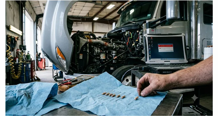
I’m standing in a fleet maintenance bay outside Birmingham. It’s three in the afternoon, and a technician I respect has a neat line of eight brand-new 120-ohm resistors laid out on a paper towel, each one having been tried, sworn at, and removed. The truck still won’t stay on the CAN bus for more than four seconds. He looks at me and says, “I’ve changed the termination four times. It’s got to be the ECU.”
It wasn’t the ECU. It wasn’t the termination. It was a configuration parameter in a diagnostic tool that was holding the CAN controller in a silent, half-baked listen-only state, flooding the bus with error frames that looked for all the world like a physical layer collapse. No resistor in the world can fix a line of code that shouldn’t be executing. That afternoon cost the fleet nearly three thousand seven hundred dollars in downtime and parts before we found the actual fault—none of which was hardware.
I’ve been engineering and diagnosing networked vehicle systems long enough to know that a terminating resistor is one of the most misunderstood and over-ordered components in our industry. I’ve seen entire warranty campaigns built around swapping ECU hardware when the root cause was a software timing mismatch that drifted with temperature. I’ve seen engineering teams reject a perfectly good harness because a scope trace didn’t match the textbook picture, not realizing the textbook picture was measured with a terminated network driven by a transceiver they weren’t using. And I’ve watched as countless hours of skilled labor were burned chasing ghosts that a simple five-minute protocol analysis would have exorcised.
This is not a rant against technicians. It’s a calm, evidence-based walk through what terminating resistors actually do, what they can’t do, and how to build a diagnostic sequence that points you toward the true root cause—whether it’s software, configuration, a marginal transceiver, or, very occasionally, a genuine termination issue. Along the way, I’ll reference what happens when the cables and terminations themselves become a variable because they weren’t designed or tested properly, and why more than a few engineering teams have moved toward working directly with factories like ours to eliminate that variable entirely.
What a Terminating Resistor Actually Does (and the One Thing It Can’t Do)
On a properly terminated bus that’s carrying traffic, a differential probe will show you a swing of about 2 volts—something close to a clean 1-volt offset from the recessive baseline. I don’t memorize the absolute voltages anymore; I look at the shape. When I see a bus where the recessive state sits cleanly at 2.3 volts instead of 2.5 volts, I know I’m probably dealing with a split-termination network on a European truck, not a fault. The ISO 11898-2 standard specifies 120 ohms to suppress reflections. The scope will tell you whether the impedance is actually matched or whether someone slapped a 120-ohm resistor onto a cable that drifts to 107 ohms when the engine bay heats up. After two decades on the factory floor watching impedance curves walk across a vector network analyzer with temperature, I can tell you a cable isn’t a fixed 120-ohm device—it’s a living curve that bends with heat and routing, and a 10% shift is all it takes to turn a clean CAN network into an intermittent nightmare.
A single 120-ohm resistor placed at each physical end of the bus absorbs the energy that would otherwise bounce back down the twisted pair. That’s it. The terminating resistor does not interpret frames. It does not acknowledge messages. It does not participate in arbitration. It is a passive component with exactly one job: stop energy from ricocheting up and down the copper. If you remove both terminators, you might still get communication across a short, quiet harness on a bench. That has fooled more than a few engineers into shipping a network that falls apart in the field once wiring lengths and environmental noise increase.
The critical point, the one that separates a cheap fix from an expensive goose chase, is this: a terminating resistor can only fix problems that originate in the physical impedance discontinuity. It cannot remedy a mismatched bit timing setting. It cannot resolve a situation where a node is transmitting frames with an incorrect identifier that no one is set to acknowledge. It cannot silence a noisy transceiver that stays stuck dominant because its firmware forgot to release the pin. If your CAN network is sick because its software is broken, adding or replacing a resistor is like replacing a transmission line terminator on a lab bench while ignoring the signal generator that’s outputting the wrong waveform in the first place.
A Diagnostic Sequence Built on Mistakes I Won’t Repeat
I wish I could say I always start with resistance. I don’t. Early on, I’d jump straight to a scope, convinced I could spot a missing terminator by the ringing on the falling edge. I wasted an afternoon on a refuse truck where the scope trace was gorgeous and the bus was still silent—because a telematics unit had dragged the differential impedance down to 41 ohms, something a thirty-second resistance check would have told me. Now I force myself to grab the multimeter first, before the scope even warms up. Here’s the order that has cost me the fewest wrong diagnoses since then.
Resistance First: The Multimeter Check That Saves Hours
Disconnect the battery. Isolate the CAN bus from all ECUs if possible, or at least power everything down. Put a multimeter across CAN High and CAN Low at the diagnostic connector. You expect to see roughly 60 ohms if two 120-ohm terminators are in parallel. If you see 120 ohms, one terminator is missing or an inline ECU with internal termination is disconnected. If you see something like 45 ohms, someone has added extra terminations or a node has a low-impedance fault. I’ve found three terminators on a truck where an aftermarket telematics unit had its own 120 ohms switched on, dragging the differential impedance down and effectively muting the bus. At this stage, do not replace anything yet. I’ve seen technicians immediately yank a module when they saw 120 ohms, then later discover the missing “resistor” was actually inside a logging tool that had been unplugged the night before.
Voltage Checks Under Power: Finding the Stuck Dominant Transceiver
Power the vehicle. With a voltmeter, measure CAN High to ground and CAN Low to ground. On a healthy bus with traffic, you’ll typically see CAN High hovering around 2.5 to 3.5 volts and CAN Low around 1.5 to 2.5 volts, with the difference being the dominant-recessive swing. If both lines sit steady at 2.5 volts, nothing is transmitting, or the bus is stuck recessive. If one line is pinned near battery voltage and the other near ground, a transceiver is likely latched dominant—often a software fault, not a resistor problem. If the voltages look plausible but the module you care about isn’t talking, proceed.
Oscilloscope Inspection: Why a Differential Probe Tells the Real Story
A single-ended scope probe can mislead. Use a differential probe or two channels in subtract mode. Trigger on the start-of-frame dominant bit. Look at the edges. Are they crisp, with just a hint of rounding from the termination? Overly sharp edges with ringing after each transition suggest a termination impedance mismatch—either the wrong value, a missing terminator, or a stub that’s too long. A waveform that looks perfectly square but still shows no acknowledgment bit after the CRC delimiter moves the problem squarely into protocol and software territory.
I carry a small battery-powered scope and a CAN transceiver breakout cable that I trust—one manufactured with precisely controlled characteristic impedance and fully tested on the same vector network analyzer bench we run every production OBD-II cable assembly through before it leaves our factory. Over the years, I’ve learned not to trust a ten-dollar cable when a million-dollar machine’s downtime is on the line. A cable that drifts from 120 ohms characteristic impedance by even 10 to 15 percent can create a phantom reflection that mimics a missing termination, and introducing that measurement artifact can cascade into a seven-thousand-dollar module replacement that solves nothing.
Protocol Analysis: Let the Error Counters Lead You to the Root Cause
If the physical layer looks clean—correct voltages, clean edges, proper differential amplitude—it’s time to connect a CAN interface and log frames. I can’t count the number of times a “bad ECU” was actually a node transmitting at 250 kbps on a 500 kbps network after a firmware flash went wrong, or a device that came up in listen-only mode and never sent its periodic keep-alive, causing the rest of the network to constantly retransmit. In both cases, the bus resistance measured fine. The voltages looked fine. The scope picture was beautiful. And still, nothing worked.
The tool’s error counter log will tell you what the CAN controllers themselves are seeing. A rising transmit error counter on one node with a clean physical layer often points to a configuration mismatch. A consistently high receive error counter on all nodes may indicate a single node sending malformed frames—again, likely a firmware issue. None of these situations yield to a resistor swap. Yet in the field, the resistor gets changed first because it’s tangible and cheap and feels like doing something.
How This Plays Out in the Real World: Two Cases
Case 1: The Diagnostic Tool That Silenced the Engine ECU
A heavy-equipment dealer was unable to connect to a new engine ECU with their service laptop. The techs verified termination resistance at 60 ohms. They tried a new ECU (roughly two thousand eight hundred dollars) and a new engine harness (another nine hundred dollars in parts, plus labor). Still no communication. They were about to condemn the entire engine control system when I was asked to look.
I connected a CAN logger between the diagnostic connector and the laptop. The moment the laptop initialized its VCI, the bus filled with a burst of frames at an identifier range that didn’t belong to any engine PGN. The tool was sending proprietary discovery frames that the ECU didn’t understand, and the ECU’s CAN controller had shut down its transmitter after its error counter crossed 255. The fix was a firmware update to the diagnostic interface—a zero-dollar software change once you knew what was happening. Total misdiagnosis cost was over four thousand dollars. Resistors had been replaced twice, pointlessly.
Case 2: The Impedance Drift That Nearly Triggered a Recall
A Tier 1 supplier was developing an off-highway controller and kept seeing intermittent communication dropouts during thermal cycling. The prototype harness they were using was assembled with commodity D-sub connectors and unvalidated cable stock sourced from a local electronics shop. During hot soak, the cable’s characteristic impedance drifted from 120 ohms to nearly 95 ohms—a shift that pushed the network into marginal territory. Because the termination resistors measured fine at room temperature, the team initially blamed the ECU firmware and nearly issued a software patch to mask a physical symptom.
The cable that replaced the failing prototype didn’t come from a catalog. It was cut to a specified length from a reel we’d verified ourselves on a vector network analyzer—something you do when a 10% impedance shift can push a bus into intermittent failure. Our production floor runs under IATF 16949 not because it looks good on a wall plaque but because it forces the traceability we need: if a batch of wire drifts, we know which twenty-three assemblies used it and we pull them before a single one reaches a customer’s test bench. The assembly itself was built to the exact length, AWG, and color the supplier specified, with connectors molded in a full-plastic design compliant with RoHS and REACH. After the swap, the dropout issue vanished. The termination didn’t change—the medium carrying the signal did. That team now insists on OEM-customized cables for every test bench, and they haven’t misdiagnosed a CAN physical-layer problem since.
Common Mistakes and What They Look Like
| Observed Symptom | The Move That Feels Right (But Isn’t) | Root Cause Often Missed | Correct Action |
| Intermittent bus-off, no pattern | Replace terminating resistors | Node entering listen-only mode after firmware watchdog reset | Analyze bus-off timing; update firmware |
| Total communication loss after replacing a module | Add extra 120-ohm resistor | New module has active internal termination already | Remove duplicate termination; measure resistance |
| CAN bus works only below certain temperature | Swap ECU | Cable impedance drift with heat; poor connector plating | Verify physical layer with TDR; replace harness with impedance-controlled cable |
| Occasional error frames on scope but clean voltages | Add termination capacitor | Stub length exceeding 0.3 m causing reflections | Shorten stub; move connector location |
| Inability to connect a diagnostic tool | Replace OBD port, resistors, cable | Tool transmitting at incorrect baud rate or with wrong protocol | Check tool configuration and firmware version |
I’ve seen all five of these misdiagnoses in the last twelve months. The first three all involved technicians reaching for a resistor before they opened a laptop.
How to Verify the Fix Actually Worked
After you’ve changed nothing but software—or after you’ve genuinely replaced a defective terminator—don’t assume the problem is solved because it fired up once. The classic trap is a cold-soak restart in the morning that reveals the problem hasn’t gone anywhere.
My validation protocol is simple:
- Clear all error counters and run the network across the full operating temperature range. If any node’s receive error counter climbs above zero, log it.
- Clear all error counters and run the network across the full operating temperature range. If any node’s receive error counter climbs above zero, log it.
- Perform a physical inspection under vibration. This is where a correctly built cable proves itself. Cables from a factory that runs a disciplined 4-step quality inspection on every assembly—raw conductor drawing, insulation extrusion, continuity, and impedance check—don’t develop micro-fractures the first time they see a shaker table. I’ve seen cheap cables fail a validation run because an intermittent open on a connector pin exactly mimicked a missing terminator, and no amount of resistor swapping would have found it.
- Monitor for 24 hours after the fix in real operating conditions.
If the error counters stay zero and the bus traffic looks clean on a scope, you can close the ticket with confidence.
When Hardware Genuinely Needs Replacing
There are times when a terminating resistor actually fails. Through-hole carbon film resistors can crack under vibration. An internal module termination circuit—often a split termination with capacitors to ground—can develop a short that pulls the bus bias off-center. But these failures leave measurable footprints: a resistance reading that’s not 60 ohms, or a common-mode voltage that’s shifted outside the transceiver’s range.
If you do need to replace a terminator or a section of harness, choose components that remove variables rather than add them. I’ve spent too many hours debugging networks where someone inserted an aftermarket resistor with a tolerance stack-up that put the overall impedance at 115 ohms instead of 120, and the bus worked until the day the humidity dropped and everything went intermittent. In two decades of building custom cable assemblies for OEMs, we’ve pulled entire production batches for a 3-ohm impedance drift that no end-user would ever notice on a bench but would absolutely cause intermittent field faults. The math on that kind of gamble changes when you realize a two-cent resistor misdiagnosis can cost a fleet thousands of dollars in wasted labor.
FAQ
1. Can a terminating resistor fail intermittently?
I’ve logged exactly two cases where the resistor itself was the intermittent. Both were through-hole carbon film resistors on early-2000s ECUs that had micro-cracked under thermal stress. On the bench, they’d read 120 ohms cold and go open circuit at 80°C. Every other “intermittent termination” I’ve tracked turned out to be a connector pin with fretting corrosion or a wire that had work-hardened and broken inside the insulation, making contact only when the harness was flexed a certain way. My rule: if the resistance changes when you wiggle the connector, the resistor isn’t your problem—the mechanical interface is.
2. Why does adding an extra resistor sometimes make the problem go away temporarily?
I’ve watched this play out on a mining truck where a technician dropped a third 120-ohm terminator into the backbone and the bus came alive for twenty minutes. What he’d actually done was dampen a reflection caused by a stub that was forty centimeters too long. The lower impedance masked the reflection enough to pass frames, but it also cut the signal amplitude at the farthest node. When the alternator loaded up and electrical noise rose, the bus fell silent again. It’s a band-aid that invites a much harder diagnosis later.
3. Can a software fault really mimic a bad termination?
Absolutely. I recall a refuse truck where a body controller was transmitting a dominant bit during the arbitration field because its firmware had a corrupted timing register. On the scope, the bus looked flat-lined—exactly the picture you’d expect from a shorted terminator. The technician had already ordered a new ECU. A quick log showed the bus wasn’t physically shorted; it was being held dominant by a node that didn’t know when to let go.
4. How do I tell if the problem is configuration vs. hardware?
Measure termination resistance and bus voltages first. If they’re correct, connect a protocol analyzer and look at the error counters. If one node’s transmit error counter is climbing while the physical layer is clean, suspect configuration. I once spent half a day on a generator controller that wouldn’t talk, only to find someone had flashed the 250 kbps firmware onto a 500 kbps network. No amount of resistor swapping would have fixed that.
5. What is the correct termination resistance for a CAN bus?
120 ohms at each end of the main bus trunk, giving 60 ohms when measured across CAN High and CAN Low with the system powered off. Some systems use split termination (two 60-ohm resistors with a capacitor to ground) for improved EMC, but the total differential impedance should still be around 60 ohms. I’ve seen European truck networks that sit a little lower, at 58 ohms, without issue—it’s the mismatch that kills you, not a two-ohm deviation.
6. My OBD cable works for one vehicle but not another. Is it the cable?
Not necessarily. Different vehicles use different CAN protocols and speeds. A cable that is electrically sound may still be incompatible if it’s not wired to support the specific OBD pin assignments the vehicle uses. However, a cable with poor shielding or impedance control can fail on a longer bus while working on a short one. This is why I insist on cables with a known, tested impedance—preferably ones that have been 100% verified on a network analyzer, not just continuity-tested.
7. How often should terminating resistors be replaced proactively?
Almost never. There is no wear mechanism in a properly installed terminating resistor. I’ve pulled original 120-ohm resistors out of fifteen-year-old trucks that still measured 120.1 ohms. Replace them only if they are physically damaged, cracked, or have drifted out of tolerance. A preventative resistor swap is a solution looking for a problem.
8. What should I look for in a test cable to avoid introducing errors during diagnosis?
Use a cable with a controlled characteristic impedance, 100% continuity and impedance testing, and molded connectors that protect against pin damage. Avoid cables that don’t specify their impedance tolerance. I look for assemblies built with full-plastic overmolding compliant with RoHS standards—an exposed solder joint inside a cheap backshell creates exactly the kind of intermittent that will send you chasing the wrong module. This is a standard we enforce under our ISO 9001 and IATF 16949 quality system, which is also backed by our ISO 14001 environmental management certification. Every reel is verified for consistent impedance and every finished cable is tested before it ships. That’s how you remove the cable itself as a variable.
9. Can a bad battery or ground cause symptoms that look like termination issues?
Yes. A floating ground or a weak battery can offset the common-mode voltage beyond the transceiver’s limits, causing intermittent recessive-dominant detection failures. I once diagnosed a combine harvester where the CAN bus would drop out every time the operator engaged the header clutch. It wasn’t a termination problem; it was a corroded chassis ground that shifted the common-mode voltage by nearly three volts under load. Always check the vehicle’s ground and supply voltage before diving into CAN-specific diagnostics.
10. Do electric vehicles or hybrids have different termination requirements?
The physics are the same, but the isolation requirements are stricter. Many high-voltage systems use isolated CAN transceivers, and a wrong termination resistor value can break the isolation barrier’s safety margin. I’ve seen a prototype battery management system where an incorrectly specified split termination allowed enough common-mode current to trip an isolation monitor. Always consult the OEM network topology documentation—and never assume the resistor value from a diesel platform transfers directly to an EV.
Stopping the Cycle of Wrong Parts
The pattern repeats across every fleet, every workshop, and every engineering lab: a network fault appears, a resistor gets changed because that’s the fastest thing to try, the fault persists, and suddenly an expensive module gets condemned on circumstantial evidence. Breaking that cycle requires two things: a diagnostic sequence that treats resistors as just one hypothesis to test, not the default answer, and a willingness to look at the ones and zeros before looking at the physical parts bin.
The physical layer absolutely matters. When we ship a custom cable assembly to an equipment manufacturer or a diagnostic tool developer, it reflects more than two decades of direct factory experience, built on production floors where impedance drift gets caught long before it becomes a field failure. That level of consistency means one less variable on the bench and in the bay. It means a technician can trust that the cable isn’t lying to them when they’re trying to separate a software fault from a hardware fault.
If you’re fighting a CAN bus problem that refuses to make sense—or if you’re building a product and want to ensure your physical layer never becomes the reason your customers replace the wrong part—reach out directly. My colleagues and I provide engineering support, OEM customization (logo, brand, length, color, AWG, connector types), and the kind of no-nonsense technical conversation that starts with a scope trace and ends with a solution.
Contact us for engineering support and OEM customization:
- WhatsApp: Chat with Linda on WhatsApp https://api.whatsapp.com/send/?phone=8617307168662&text=Need+Help%3F+Chat+linda+WhatsAPP&type=phone_number&app_absent=0
- Contact Page: https://obd-cable.com/contact/
That technician with eight resistors on a paper towel taught me something I never want to forget: the physical layer demands respect, but the signal always tells the truth first. Listen to it.
