

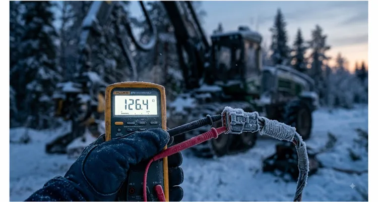
A few years ago, I spent a week at a logging operation in northern British Columbia. The mornings were around -38°C, and every day the same harvester would throw CAN bus errors until the cab warmed up. After three days of swapping ECUs, checking wiring harnesses, and reloading software, we finally measured the terminating resistor with the connector cold-soaked. It read 126.4 ohms on one end. The spec called for 120. That was the moment the real troubleshooting started.
This article covers the measurement protocol I have used since then, why termination resistor drift happens harder in forestry equipment than in most other machines, and how to fix it without replacing ECUs, harness sections, and terminators before you have a measurement.
What Termination Resistor Drift Looks Like in a Forestry Machine
A cold morning in Alberta or northern Sweden
I have seen the same sequence on forestry machines more times than I can count. The machine starts, the engine runs, but the J1939 bus is full of error frames. The display freezes or shows missing data from the transmission controller. The operator cycles the key and sometimes it comes back. Other times it takes twenty minutes of idling before the messages start flowing again.
By mid-afternoon, once the cab heat has soaked through the harness, the bus behaves normally. If you’ve been chasing intermittent J1939 faults, that temperature dependence should point you straight to the terminating resistors—not to the engine ECU. This is the first sign of termination resistor drift in cold weather.
Why the bus won’t come back up
J1939 is a two-wire differential bus running at 250 kbit/s or 500 kbit/s, part of the CAN bus standard. It needs a defined impedance to keep signal reflections from destroying the bits. The two 120-ohm resistors—one at each end of the backbone—create a 60-ohm load when measured from any point on the bus. If one of those resistors moves a few percent away from 120 ohms, the bus still works at room temperature. But add extreme cold, moisture ingress, and a marginal resistor, and the edge of the eye pattern closes. The controller can’t distinguish a dominant bit from a recessive bit. The error counter climbs until the node reaches 255 and stops transmitting. At that point the controller appears offline to the rest of the machine, and the display freezes or shows comm errors. That is the cold-start failure pattern I see most often on logging equipment.
The diagnostic port measurement everyone trusts too much
Most technicians measure between CAN_H and CAN_L at the 9-pin diagnostic connector. They see 60 ohms and mark the bus as healthy. The issue is that a parallel measurement hides individual resistor drift. If both resistors drift the same direction, the reading at the diagnostic port may still show 60 ohms. You need to measure each terminating resistor separately, and you need to do it at the temperature where the problem happens. Otherwise, you’ll never catch the termination resistor drift that only appears during a cold-soak. For more on the multimeter side of this test, see our J1939 physical layer multimeter diagnostics guide.
The Root Cause: Temperature Coefficient and Mechanical Stress in CAN Terminators
The 120-ohm baseline, but not really
A J1939 terminating resistor is not a perfect 120.000 ohms. Most are thick film chip resistors or metal film resistors with a tolerance of 1% or 5%. That means at 25°C, one resistor can be anywhere from 118.8 to 121.2 ohms and still meet a 1% spec. That tolerance is fine. The CAN transceivers are designed to tolerate some mismatch. But tolerance is not the main issue. The temperature coefficient of resistance, or TCR, is what causes drift.
TCR math that matters in a logging machine
A typical thick film resistor has a TCR of 100 to 200 ppm/°C. Let’s run the numbers for a 120-ohm resistor with a 150 ppm/°C TCR. At -40°C, the temperature difference from 25°C is 65 degrees. The resistance change is:
120 ohms × 150 × 10⁻⁶ × 65 = 1.17 ohms
So the resistor reads about 121.2 ohms at -40°C. That’s a 0.98% shift. The parallel combination of two such resistors would be about 60.6 ohms instead of 60.0 ohms. That’s usually still acceptable for CAN bus terminating resistor cold weather failure margins. I covered the hot-versus-cold drift behavior in a separate article on J1939 termination resistance drift hot vs cold.
The hidden series resistance at the connector crimp
But many forestry machines use terminators that are not just a resistor. They are integrated into a molded connector with crimped terminals. Cold contraction, moisture, and vibration add series resistance at the crimp and contact interface. I have measured an additional 2 to 4 ohms of series resistance at cold-soaked Deutsch connectors. That’s how you get a single terminator reading 126 ohms on a -38°C morning.
Why forestry is harder on terminators than on-road trucks
A highway truck sees temperature swings, but the harness is usually dry and the connectors are protected. A forestry harvester works in wet snow, frozen mud, and then gets parked in a heated shop overnight. That thermal cycling pulls moisture into the connector cavities. The terminals oxidize slightly. The resistor’s solder joints flex. Over a few hundred cycles, the resistance creeps up. I’ve seen machines with 6,000 hours on them read 135 ohms at one terminator after a cold soak. At that point the bus only works after warm-up. This is exactly the kind of failure we document in our forestry J1939 harness failures field repairs article.
Measurement Protocol: A Step-by-Step Field and Bench Procedure
This is the protocol I have used on forestry equipment. It works in the field with a good multimeter, and it gives repeatable results if you follow the steps. For accurate termination resistor drift measurement, you need to follow all six steps.
Tools you’ll need before you start:
- A 4-wire milliohm meter or a high-resolution digital multimeter with 0.01-ohm resolution and a null function
- A thermocouple or infrared thermometer to measure the connector temperature
- The machine’s wiring diagram, if available
- A CAN bus analyzer, such as a PEAK PCAN-USB, for verification after repair
Step 1: Power down and disconnect the batteries
Do not measure resistance on a powered CAN bus. The transceiver bias voltage will ruin the reading and can damage your meter. Turn off the master switch, disconnect the negative battery cables, and wait at least five minutes for the ECU capacitors to discharge. On some machines, you may need to disconnect both batteries if there is a two-battery 24-volt system with a DC-DC converter.
Step 2: Locate the two terminating resistors
On most forestry machines, one terminator is near the engine ECU or the transmission controller. The other is near the cab controller or at the far end of the machine’s backbone harness. Look for a 3-pin or 2-pin weatherproof connector with a resistor molded into the shell. Sometimes the terminator is inside the ECU connector itself. If you have a wiring diagram, find the two nodes marked “TERM” or “120R.” If you don’t have a diagram, unplug one connector at a time and watch the diagnostic port resistance. When the reading jumps from 60 ohms to 120 ohms, you’ve found one terminator.
Step 3: Bring the resistor to a known temperature
If you do only one thing differently from the standard J1939 diagnostic routine, make it this: measure at the temperature where the fault occurs, not at the temperature of the shop. If the problem only happens at -30°C, you need to measure at -30°C. On a cold morning, leave the connector exposed for at least one hour before measuring. If you are doing a bench test, put the terminator in a freezer or an environmental chamber. Record the ambient temperature next to the resistor with a thermocouple, not the cab temperature. The connector’s thermal mass means it lags behind the air temperature by 10 to 20 minutes.
Step 4: Use the right meter
A meter that resolves only to 0.1 ohm will show 126.4 ohms as 126 ohms, which looks fine. You’ll miss the 5% shift that is causing the bus to fail. Use a meter with 0.01-ohm resolution and a null function, or a 4-wire Kelvin setup. If you use two-wire measurement, measure the lead resistance first by touching the probes together and subtract that from the reading. I use a Fluke 87V for field checks and a bench LCR meter for lab verification. The LCR meter gives you a true resistance reading at DC, which is what the bus sees. For a broader multimeter diagnostic approach, see our J1939 physical layer multimeter diagnostics guide.
Step 5: Record and calculate deviation
Measure the resistor at the temperature where the fault occurs. Measure both terminators separately. Record the values and the temperature. Calculate the percentage deviation from 120 ohms:
Deviation % = ((Measured – 120) / 120) × 100
Also measure the parallel combination at the diagnostic port. If the parallel reading is outside 57.0 to 63.0 ohms at 25°C, or 55.0 to 65.0 ohms at extreme temperatures, the bus impedance is no longer well controlled.
Here is a table from a real logging harvester I tested. The temperatures are approximate because the machine had been parked overnight.
| Location | Temperature at Connector | Single Terminator Reading | Parallel Bus Reading | Deviation | CAN Bus Behavior |
| Engine ECU end | -34°C | 126.4 Ω | 62.3 Ω | +5.3% | Intermittent errors |
| Cab end | -34°C | 121.8 Ω | 62.3 Ω | +1.5% | — |
| Engine ECU end | +22°C after warm-up | 120.6 Ω | 60.1 Ω | +0.5% | Normal |
| Cab end | +22°C | 120.2 Ω | 60.1 Ω | +0.2% | Normal |
That single terminator reading 126.4 ohms is a 5.3% deviation. Once the engine bay warmed up, the same terminator dropped to 120.6 ohms. The drift was not permanent—it was thermal and mechanical, driven by a failing crimp inside the connector.
Step 6: Decide pass/fail
I use a simple rule for J1939 on forestry machines. A single terminating resistor should be between 118.0 and 122.0 ohms at 25°C. At -40°C, allow up to 125.0 ohms. At +85°C, allow down to 115.0 ohms. If a terminator is outside that range when measured at the fault temperature, replace it. Do not wait for a total bus failure. At -40°C, you have only a few ohms of margin before a machine won’t communicate. That’s not a margin I’m willing to leave untested.
Five Mistakes That Produce False Drift Readings
- Measuring at the diagnostic port without isolating the terminators. The parallel combination hides individual drift. If both resistors are 126 ohms, the port reads 63 ohms, and most people think it’s fine.
- Using a cheap meter with 0.1-ohm resolution and long test leads. The lead resistance alone can be 0.2 to 0.5 ohms. If you don’t null it out, you’ll chase a phantom drift.
- Measuring a warm connector and assuming it represents the cold condition. Thermal mass delays the temperature change. The resistor might be at 10°C while the air is -30°C if you just carried it from a heated truck.
- Measuring with the battery still connected. Even with the key off, some ECUs maintain a bias voltage on the bus. That voltage will corrupt the resistance reading.
- Forgetting to check the connector terminals, not just the resistor. A crimp can add 2 to 5 ohms of series resistance when cold. The resistor itself may be perfect, but the assembly is not. Always measure from the wire side, not the mating face, and include the crimp in the measurement.
How to Confirm the Fix Actually Worked
After replacing a drifted terminator or repairing a connector, do not just clear the fault codes and call it done. Re-run the same measurement at the same temperature. The single terminator should now read within the acceptable range. The parallel bus reading should be close to 60 ohms.
Then run the machine through a full cold-soak cycle. Park it outside overnight, or in a cold chamber if you have access to one. In the morning, before starting the engine, connect a CAN bus analyzer or a scan tool. Watch the error frames for the first ten minutes. A healthy bus should have zero error frames or only an occasional one during ECU synchronization. If you still see a burst of errors during cranking, you have another problem, likely a wiring harness or a different terminator.
One practical test I use is to record the bus traffic with a PEAK PCAN-USB adapter and look at the error counter graph. After the fix, the error counter should stay flat during cold start. If it climbs even slightly, go back and measure each terminator again. I’ve tried clearing codes and calling it fixed. The bus always tells the truth the next cold morning.
Related Hardware That Reduces the Problem
The terminating resistor itself is usually a commodity part, but its integration into the cable assembly determines how well it survives forestry conditions. At our factory, we build J1939 backbone cables and diagnostic cables for equipment manufacturers who operate in northern climates. We have seen the same failure modes over and over.
Two things make a difference. First, use a low-TCR metal film resistor, typically 50 ppm/°C or better, instead of a thick film resistor. That alone cuts the thermal drift by more than half. Second, crimp the terminals with a proper four-indent crimper and seal the connector with a dual-wall adhesive heat-shrink. That prevents moisture from reaching the crimp and adding series resistance. For a deeper look at resistor choice, see our J1939 split termination vs 120 ohm guide. We also documented the real cost of ignoring this issue in our 23-cent resistor fleet downtime cost article.
We build these cables in-house at an IATF16949 and ISO 9001 certified factory that has been making J1939 and CAN cable assemblies since 2004. Our warehouse is held at 22°C and 40% RH to keep connectors dry, and our environmental management system is certified to ISO 14001. We use full-plastic overmolded connectors with no exposed metal that can corrode. Before shipping, each assembly goes through four checks: dimensional, continuity, insulation resistance at 500V DC, and a thermal shock from -40°C to +85°C for 10 cycles. We do this on 100% of production, not just sample lots. All raw materials meet RoHS, CE, and REACH standards where required.
If you are dealing with repeated termination resistor drift and need a cable assembly with a tighter TCR or a custom connector configuration, send us a note through the contact page or WhatsApp. We do OEM work—connector brand, cable length, AWG, resistor placement—all built to your drawing. We don’t publish pricing or inventory because most of what we build is custom. If you have a drawing or a failed sample, send it over and we’ll work from the connector shell to the resistor tolerance.
FAQ
What is the standard resistance of a J1939 terminating resistor?
A single J1939 terminating resistor is 120 ohms, but in forestry machines the actual value you measure depends on the resistor’s tolerance and the connector. Most OEMs use ±1% parts, so at 25°C you’ll see between 118.8 and 121.2 ohms. With both terminators installed, the bus reads about 60 ohms because the two 120-ohm resistors are in parallel.
How much drift is acceptable before the CAN bus fails?
In forestry machines, I allow a single terminator to drift to 125 ohms at -40°C or 115 ohms at +85°C. Beyond that, the bus impedance mismatch can cause intermittent errors during cold starts. The exact failure point depends on the transceiver and the harness capacitance.
Why do forestry machines see more termination resistor drift than highway trucks?
Forestry equipment operates in wet, frozen conditions with frequent thermal cycling from cold outdoor parking to heated shops. Condensation, vibration, and repeated flexing of the harness create series resistance at the connector terminals. A highway truck harness is usually drier and more stable.
Can I measure the terminating resistor without disconnecting the battery?
No. Even with the key off, some ECUs apply a small bias voltage to the CAN bus. That voltage will distort the resistance reading and can damage a multimeter. Always disconnect the batteries and wait for capacitor discharge.
What type of multimeter do I need for accurate drift measurements?
A high-resolution meter with 0.01-ohm resolution and a null function is the minimum for field work. A 4-wire Kelvin measurement setup is better for bench testing. Avoid meters with only 0.1-ohm resolution because the test lead resistance alone can be larger than the drift you are trying to measure.
Should I replace both terminating resistors if one drifts?
Usually yes. If one terminator has been thermal-cycled enough to drift, the other one has seen the same environment and is likely close behind. Replacing both at the same time restores symmetry and gives the bus a clean reference. For more on the economics of replacing these parts, see our 23-cent resistor fleet downtime cost article.
How do I find the terminating resistors on a forestry machine?
Look for a weatherproof 2-pin or 3-pin connector near the engine ECU and at the far end of the machine’s backbone harness. Some machines integrate the terminator inside the ECU connector. If you have a wiring diagram, search for nodes marked “TERM” or “120R.” Otherwise, unplug connectors one at a time and watch the diagnostic port resistance.
Can I use a low-TCR resistor as an upgrade?
Yes. A metal film resistor with a TCR of 50 ppm/°C or lower will cut thermal drift significantly compared to a standard thick film resistor. Just make sure the power rating and package size match the original, and the connector sealing is done correctly.
What is the difference between a 120-ohm terminator and the 60-ohm measurement at the diagnostic port?
The 120-ohm measurement is taken across a single terminator after isolating it from the bus. The 60-ohm measurement is the parallel combination of both terminators. Measuring only at the diagnostic port hides individual drift because two high resistors in parallel can still show 60 ohms.
How often should termination resistors be checked in a forestry fleet?
I recommend checking them every 1,000 operating hours or at the start of each winter season, whichever comes first. In my experience, most drift faults show up between 800 and 1,200 hours after the last thermal cycling, so a 1,000-hour check catches them before they strand a machine. The check takes less than 30 minutes per machine and can prevent a lot of cold-start downtime. If a machine already shows intermittent CAN errors in cold weather, check immediately.
