

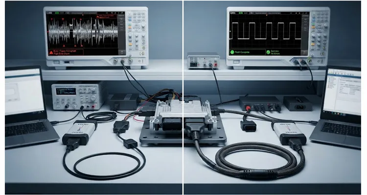
Last month I spent three hours on a Vector VN1630A setup that kept dropping CAN FD frames during a bootloader erase. The ECU passed on a reference bench. The software build was identical. The only variable left was the two-meter J1962 harness we had pulled from a spare parts bin. It was black, it had the right connector, and it tested fine on a continuity checker. But under load, it was the reason our flash kept aborting.
That harness was a commodity OBD cable—the kind you can buy at any auto parts counter or from a dozen online sellers. It looks identical to the one on your bench. But on an ECU programming bench, a HIL rig, or an end-of-line flashing station, the requirements are fundamentally different from reading a diagnostic trouble code in a parked car. This article is about the specific, measurable ways those differences cause intermittent flash failures, and what to specify instead.
The Physics of Failure: Why “It Works in the Car” Fails on the Bench
In a vehicle, the OBD port is a passive access point. You plug in a scan tool, read some PIDs, maybe clear a code, and unplug. The duty cycle is low. The cable spends most of its life coiled in a glovebox.
On a programming bench, that same cable becomes an active circuit element. It gets flexed thousands of times during harness validation. It sits next to switching power supplies that radiate electromagnetic interference. It gets stepped on, bent against sharp edges, and pulled at odd angles. Most critically, it is expected to maintain exact impedance and minimal resistance across thousands of write cycles while carrying both high-speed differential signals and bursts of current.
Three failure modes dominate when a commodity cable is used in this environment.
Voltage Drop During Bootloader Current Spikes
When an ECU enters bootloader mode for a flash erase or write, its current draw spikes. On a bench we measured this directly: a mid-range body control module drawing 80 milliamps in normal operation jumped to 450 milliamps during the flash erase phase. If the cable uses 24 AWG or 26 AWG conductors—common in cheap J1962 assemblies—the resistance per meter is high enough to cause a significant voltage drop.
We back-probed the connector at the ECU and found the supply voltage sagging from 12.0 volts to 11.3 volts during that current spike. A drop from 12.0V to 11.4V might not trigger a dashboard warning light, but during a flash erase/write cycle, the ECU’s internal voltage monitoring is looking for stable thresholds. If the voltage sags at the exact millisecond the processor commits data to flash memory, you get a checksum error. The ECU doesn’t know the cable was too thin; it just knows the write failed.
You need thicker copper for pin 16. An instrumentation-grade partner will typically offer custom AWG selection specifically for this reason—beefing up pin 16 while keeping the rest of the bundle flexible. This is not a trivial detail; we have written separately about test bench OBD cable AWG and loop resistance because conductor gauge directly maps to flash success rates.
Capacitance and Crosstalk on the CAN Bus
Modern ECU flashing increasingly uses CAN FD or high-speed CAN at 500 kbps, 1 Mbps, or higher. At these frequencies, the cable is no longer just a copper conductor—it is a distributed capacitor and inductor. Generic OBD cables often run all 16 pins straight through as a flat bundle. The twisted pair for CAN-H and CAN-L is rarely a true twisted pair in these cheap builds; it is just two parallel wires in a ribbon. This causes impedance mismatch and crosstalk.
On a two-meter non-shielded 16-conductor flat cable, we measured line-to-line capacitance of approximately 58 picofarads per meter between adjacent data lines. A proper CAN twisted pair with a controlled lay length typically measures around 18 picofarads per meter. That difference may sound small, but at 1 Mbps, the extra capacitance slows the rise time of the differential signal by roughly 40 nanoseconds. Depending on the transceiver tolerance, that is enough to push the edge beyond the sampling window. The transceiver sees a distorted square wave. The ECU rejects the frame. The software reports a communication timeout that has nothing to do with the application layer.
Mechanical Intermittency at the Header
This is the most common failure I have seen in contract manufacturing environments. The J1962 male connector on a commodity cable uses stamped pins with low normal force. After a few hundred insertion cycles on a test fixture—or even after sitting in a humid storage cabinet for a season—the pin expands or corrodes slightly. The cable will test fine on a continuity checker with a steady current. But under vibration from a cooling fan, or a slight lateral pull on the harness, the resistance on the K-Line or the power ground jumps to kilo-ohms for a microsecond. That is enough to drop the bus and kill a flash session. This is the same failure class we see in field harnesses where moisture ingress causes pin-to-pin leakage current, except here the trigger is mechanical rather than environmental.
You will spend three hours swapping the ECU, reloading the software, and rechecking the power supply, only to realize the problem was the cable intermittently losing pin 16, the battery power feed.
The Instrumentation-Grade Difference: A Bench-Specific Comparison
An instrumentation-grade OBD cable is treated as a test accessory, not a retail spare part. It must meet the same repeatability standards as the rest of the bench. The difference starts at the conductor level and extends all the way to how the cable is terminated and tested.
Here is a comparison focused on why each characteristic matters specifically for ECU programming bench work:
| Characteristic | Commodity OBD Cable | Instrumentation-Grade OBD Cable | Why It Matters for Bench Flashing |
| Conductor (Power/Ground) | Often 24-26 AWG, CCA (Copper Clad Aluminum) | 18-20 AWG, Oxygen-Free Stranded Copper | Voltage sag during bootloader current spikes can corrupt flash memory writes |
| Conductor (Data) | Parallel strands, no specific lay | Twisted pair (CAN-H/CAN-L) with controlled lay length | Maintains differential impedance, prevents signal reflections at CAN FD speeds |
| Shielding | None or foil only (drain wire not terminated properly) | Braided shield (85%+ coverage) with 360-degree termination to backshell | Prevents CAN frame errors from adjacent switching power supplies and motor drives |
| Connector Material | Stamped steel or brass, flash gold | Solid brass, 15 or 30 microinches gold over nickel | Gold thickness directly determines insertion cycle life before intermittent contact begins |
| Jacket | PVC, hardens below 0°C, cracks easily | Polyurethane (PUR) or TPE, oil-resistant, flexible to -40°C | Survives bench abuse, rolling chairs, and daily re-routing without cracking |
| Termination | Cold solder or crimp without strain relief | Over-molded strain relief or screw-lock backshell with cable clamp | Prevents wire breakage at the connector, the most common mechanical failure point |
| Test Data | None (visual inspection only) | 100% continuity, hipot, and capacitance verification per batch | Ensures consistent electrical performance, not just “it passes continuity” |
This table is not about marketing grades. It is about eliminating variables. When a flash fails at 80%, you want to know the cable is not the reason.
The Real Cost of Intermittent Failures
On a production floor, the concept of “good enough” is a trap. If you are building a fixture that will run twenty-four hours a day to flash a thousand ECUs a week, you need a cable that behaves the same on Monday morning as it does on Friday night.
A tier-one supplier had a bench running a new body control module. They installed a standard aftermarket OBD cable. Over a month, they experienced a two percent failure rate on flashing. That seems low. But if they are flashing five thousand units a month, that is one hundred units failing per month.
An operator has to pull the unit, check the log, re-seat the cable, and retry. If it passes on the retry, the unit goes into a “suspect” bin for manual re-flashing. The engineering time to investigate these ghost failures often costs more than the one hundred dollars saved by buying the cheapest cable. We have seen facilities lose six to eight hours of engineering labor troubleshooting an intermittent bus fault that was ultimately traced to a bent pin in a commodity connector.
A direct factory partner that operates under ISO 9001 and IATF 16949 standards treats the cable as a controlled component, not a consumable. At our facility, where we have been handling harness assembly for over twenty years, the process is strict. We do not just cut wires and crimp pins; we follow a four-step quality inspection process.
This starts with incoming material inspection, verifying AWG and copper purity. It moves to inline checks during crimping, measuring the pull-force of every terminal. It proceeds to one hundred percent continuity and insulation resistance testing on the finished assembly. Finally, it ends with a visual and dimensional check under magnification. This is standard for a factory supplying test equipment, but it is almost never done for a retail spare part. We perform continuity and 500 VDC IR testing on every batch because microampere leakage paths are invisible to a basic multimeter. The result is a cable that survives in a climate-controlled warehouse, stored under 5S management, without degrading before it even reaches the customer.
Common Mistakes That Corrupt Your Bench Data
If you are designing a bench now, you will likely be tempted to build the cable yourself or grab one from the IT closet. Here are the mistakes I see most often repeated by otherwise excellent test engineers.
1. Ignoring Shield Termination Path
Some engineers think that buying a “shielded” cable solves everything. But if the braided shield is not connected to the metal shell of the J1962 connector—and from there to the chassis ground of the bench—it acts as an antenna. It actually makes the noise worse.
I once saw a bench where a shielded OBD cable was terminated to a plastic J1962 shell. The shield was floating. We put a current clamp on the shield and found 2.3 milliamps of noise current flowing on it during a flash cycle. That current was coupling directly into CAN-L, causing exactly the kind of intermittent timeout that gets blamed on the ECU. Once we tied the shield to chassis ground at both ends via a low-inductance strap, the bus errors disappeared.
A proper instrumentation cable should have a low-impedance path for that shield to drain. In a plastic J1962 shell, there is nowhere for that shield to go, making the shielding useless.
2. Forgetting the Power Pins
In a standard J1962, pins 4 and 5 are ground, and pin 16 is battery positive. Commodity cables often use the same thin wire for pin 16 as they do for pin 9, which might be a low-current signal. When the ECU draws high current during a write cycle, the thin wire on pin 16 acts as a heater. If you are using a commodity cable, check the temperature of the wire near the connector during a long flash. If it is warm to the touch, you are dropping voltage.
You need thicker copper for pin 16. An instrumentation-grade partner will typically offer custom AWG selection specifically for this reason—beefing up pin 16 while keeping the rest of the bundle flexible.
3. Running All 16 Pins Straight Through
This is a simple one but devastating. You have a harness for a European vehicle using pin 7 for K-Line, but your bench is set up for a US protocol using pin 2 for J1850 PWM. A generic OBD2 cable with all 16 pins wired straight through will pass the signal, but it will introduce noise and reflection on the unused pins that can corrupt the bus you are using.
Instrumentation cables for benches are often selectively loaded—meaning only the specific pins required for that ECU program are populated, with the rest left open or connected to a drain. This requires customization, but it dramatically reduces crosstalk and makes troubleshooting easier.
Selective Pin Loading: The Customization Most Benches Need
When you are dealing with high-value equipment from companies like National Instruments, dSPACE, or Vector, you are not just buying a length of wire. You are buying a specific impedance profile and a specific pinout strategy.
A bench might need a two-meter cable with a right-angle connector to clear the safety lid. Or it might need a five-meter cable with a proprietary color code for the floor operators. A retail commodity cable cannot give you that. But a direct factory with OEM customization capabilities can.
You should be able to specify three things without negotiation:
- Length: Exactly what the bench layout requires, such as 1.5 meters or 3 meters, to avoid excess cable coiling on the deck. Coiled cable creates inductance that degrades signal edges.
- Pin population: Only the power pins (4, 5, 16) and the specific bus pins (6 and 14 for CAN, 7 for K-Line) are wired. The remaining pins are left open or tied to a drain. This is selective pin loading. We adapt a similar approach from our separated pin 4 and pin 5 OBD harness work for fleet telematics, but tuned for bench repeatability.
- Jacket color and marking: Different jacket colors for different voltage rails or test phases—red for power, blue for data—plus custom logos and part numbers printed on the jacket so your logistics team can inventory them correctly.
This level of control eliminates the “mystery cable” problem in the lab. When every cable looks the same, a technician might grab a cable intended for a GM bench and plug it into a Toyota rig. If the pinout is wrong, you blow a driver. If the cable is customized and labeled, that risk disappears.
A 4-Minute Field Test to Isolate Cable Faults
You do not need a million dollars worth of equipment to verify if your current cable is the problem. Here is a quick step-by-step debugging process I use when a bench starts acting flaky.
Step 1: The Wiggle Test
Start a continuous data stream on the CAN bus. Firmly grip the J1962 connector and gently wiggle it side to side while watching the scope. If the waveform distorts, you have a mechanical connection issue or a broken internal wire near the strain relief.
Step 2: The Voltage Check
Put a multimeter on the ECU side of the harness, or back-probe the connector. Compare the voltage at the power supply output to the voltage at the ECU during the high-current phase of the flash. If the difference is more than 0.5 volts, your cable has too much resistance.
Step 3: The Visual Inspection
Look at the pins inside the OBD port. They should be bright brass or gold. If they look dark or grey, or if you see green oxidation, the plating is gone. That cable is now a resistor, not a conductor.
Step 4: The Destructive Pull Test
If the cable fails, cut it open—assuming it is disposable. Look at the conductors. If you see silver-colored wire instead of bright copper, you just discovered Copper Clad Aluminum (CCA). CCA has significantly higher resistance than pure copper and is a hallmark of commodity cables that should never be used on a bench.
Benchmark Setup: Measuring the Difference on a Real Bench
To make this concrete, here is a benchmark we ran on a test bench using a Vector CANoe interface, a production ECU in bootloader mode, and a controlled power supply set to 12.0 volts.
Benchmark conditions: 1.5-meter OBD cable, CAN FD at 1 Mbps, ECU performing a full flash erase and rewrite cycle.
With a commodity 24 AWG flat cable, we measured a voltage drop of 0.9 volts at the ECU during the 350-milliampere erase current. The CAN bus showed intermittent error frames on the oscilloscope, with signal overshoot and ringing on the rising edge. Out of twenty flash cycles, two failed with a negative response code 0x72, indicating a general programming failure. The cable was warm to the touch near pin 16.
With an instrumentation-grade 18 AWG twisted-pair cable with braided shield and selective pin loading, the voltage drop at the ECU was 0.2 volts under the same load. The CAN waveform was clean, with rise times within the transceiver specification. All twenty flash cycles completed successfully. The cable remained at ambient temperature.
This is not a laboratory curiosity. It is the difference between a bench that runs unattended and one that requires constant human intervention.
Conclusion: The Bench Is a Single Circuit
The ECU, the power supply, the software, and the cable form a single electrical system. If you treat the cable as an afterthought, you introduce a random variable into a process that requires extreme precision. You spend your nights chasing ghosts.
Investing in an instrumentation-grade OBD cable does not just buy you copper and plastic. It buys you repeatability. It removes the “did we try a different cable?” question from your troubleshooting checklist.
We have been manufacturing harnesses and cable assemblies for over twenty years, operating under ISO 9001, ISO 14001, and IATF 16949 standards. We understand the difference between a cable that works in a car and a cable that works on a bench. If you are planning a new test rig or standardizing your current lab setup, it is worth having a conversation about what you actually need at the conductor level.
Need to spec a custom harness for your bench? If you are dealing with intermittent faults or need a specific pinout or length, do not guess. Our engineering team can help you define the exact AWG, shielding, and pinning for your application.
- Chat with Linda on WhatsApp: Discuss Your Project with Linda
- Visit our Contact Page: Submit an Engineering Inquiry
We support OEM customization for length, color, logo, and pin selection to match your exact floor specifications.
FAQ: Bench OBD Cable Decision Guide
1. How do I know if my bench OBD cable is causing CAN errors, or if it is the ECU?
Run the wiggle test described above while watching the CAN bus on a scope. If the waveform distorts when you move the connector, the cable is the problem. If the waveform stays clean but the ECU still rejects frames, the issue is elsewhere. Swap in a known-good instrumentation-grade cable and see if the failure rate changes.
2. What length of OBD cable is safe for 1 Mbps CAN flashing on a bench?
Keep it as short as your layout allows, ideally under two meters. If you need three meters or more, specify 18 AWG power conductors and a low-capacitance twisted pair for CAN. Longer runs increase both resistance and capacitance, which distort the signal.
3. Can I use an OBD splitter cable on a HIL rig?
Only if the splitter is built for that purpose with individually shielded branches and passive isolation. A generic Y-cable creates severe impedance mismatch and reflections. It is better to use a properly terminated breakout box with individually routed signals.
4. What is the difference between a “bench” OBD cable and a “vehicle” OBD cable?
A vehicle cable is designed for low insertion cycles and casual data reading. A bench cable is designed for high insertion cycles, low voltage drop, and high signal integrity under continuous use. The difference is in conductor gauge, twisting, shielding, and connector plating thickness.
5. Why does my flash sometimes work and sometimes fail with the same cable?
Intermittent flashing failures are almost always physical layer issues. The cable is losing connection for a few milliseconds due to vibration, flexing, or thermal expansion. Check the pin tension and the shield termination. A continuity checker will not catch these microsecond interruptions.
6. How much voltage drop is acceptable on a bench OBD cable?
Less than 0.5 volts during the highest current phase of the flash. If you measure more, replace the cable or increase the AWG of the power conductors. Most ECUs will tolerate a small sag, but during flash writes the margin is much tighter.
7. Can I get a cable with only specific pins populated?
Yes. This is called selective pin loading. For bench use, you often want only the power pins (4, 5, 16) and the specific bus pins (6 and 14 for CAN, 7 for K-Line) populated. Leaving the other pins out reduces noise and simplifies troubleshooting.
8. What jacket material is best for a test bench?
Polyurethane (PUR) or TPE is preferred. PVC becomes stiff in cold labs, cracks over time, and is less resistant to oils and solvents. PUR remains flexible and resists abrasion from being run under equipment or through cable trays.
9. Does the color of the cable affect its electrical performance?
No. The pigment in the jacket does not change the electrical characteristics. However, color coding is crucial for floor management and error-proofing. Use red for power, blue for data, and yellow for special test lines to prevent technicians from grabbing the wrong harness.
10. Are UL and CE markings necessary for bench OBD cables?
Yes. Since these cables are part of a professional electrical installation on a test bench, they should meet basic safety standards for flame retardancy under UL and electromagnetic compatibility under CE. This ensures they do not introduce a fire or noise hazard in the lab. For more on jacket flame ratings, see our note on UL 94 V-0 rated diagnostic cables.
