

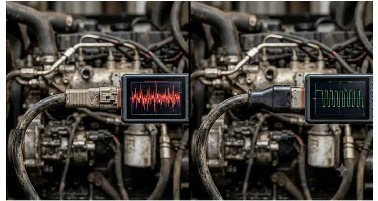
The bus went down at the worst possible moment.
A customer in northern Iowa was running a 24-row planter behind a Tier 4 tractor, and right when the GPS guidance needed its tightest correction, the entire CAN network locked up. No fault codes. No damaged wires. Just a screen full of timeout errors, and an engine ECU that refused to talk to the transmission controller for three agonizing seconds. They’d swapped ECUs, replaced the J1939 backbone harness, even shielded the cables with tinfoil out of desperation — and the bus was still glitching every time the planter’s electric drive motors ramped up.
What finally fixed it wasn’t a new ECU. It was a split termination on the J1939 backbone — two sixty-ohm resistors and a small capacitor to ground, placed at one end of the bus instead of the standard single 120Ω resistor.
This isn’t a “theoretical improvement.” In electrically brutal environments — tractors with variable-frequency drives, construction equipment sharing a chassis with high-current hydraulic solenoids, marine engines running next to inverters — a split termination isn’t a nice-to-have. It’s the difference between a bus that works every ignition cycle and a bus that drops frames at random, making your customers question everything except the actual culprit.
If you’ve ever chased an intermittent J1939 fault that made no sense, and you’re still using a standard 120Ω terminator at both ends, this write-up is for you.
When the Standard 120Ω Terminator Becomes a Liability
Ask any field tech who’s spent a few winters chasing ghost faults, and they’ll tell you a J1939 backbone looks simple on the schematic: two wires, 250 kbit/s, 120Ω characteristic impedance, terminated at both ends to stop reflections — a principle baked into the CAN bus physical layer specification. On a two-meter bench harness in a quiet lab, a pair of carbon-film resistors across CAN_H and CAN_L works every time. Sweep the bus with a network analyzer and the Smith chart stays boringly glued to 120 ohms from DC out to 10 MHz. The differential signal swings about two volts, the recessive level settles at 2.5V, and you could email the scope capture to your mother and she’d call it a flat line.
But roll that same network into a self-propelled sprayer with a PWM-controlled pump, or a city bus where an electric cooling fan hammers eighty amps to ground through a mechanical relay, and you’ve just introduced a transient the textbook never prepared you for. The CAN lines are now riding on a common-mode voltage that pumps several volts at frequencies that shred your bit timing — exactly the kind of common-mode noise that silently kills J1939 communication. The twisted pair stops looking like a differential transmission line and starts behaving like a guitar string being strummed by a switching IGBT.
Common Signs Your J1939 Bus Needs a Split Termination
Before we even clip a scope probe onto the machine, there are five or six symptoms that practically shout “common-mode noise” instead of “dead ECU”:
- Intermittent bus-off errors that arrive exactly when a specific load switches on — a hydraulic pump clutch, an electric cooling fan, a PTO engagement. We’ve seen these intermittent J1939 faults locked to 1800 RPM more times than I can count.
- The CAN bus recovers by itself after a few seconds, then drops again under the identical load.
- You’ve already swapped an ECU and the identical trouble code came back within a shift.
- The machine mixes old and new ECUs, and the older designs always drop offline first.
- A static resistance check of the harness looks perfect, but the network falls apart the moment the machine is under dynamic load.
If that list reads like your last two service calls, the fault is almost certainly physical, not logical — and a standard 120Ω terminator can’t touch it. Here’s why.
A resistor from CAN_H to CAN_L answers exactly one question: “Is the differential mode terminated?” Yes, at DC and low frequency, it is. But ask that same resistor to deal with the 4 MHz common-mode spike that appears every time the PWM drive chops current, and it simply shrugs. Why? Because the only AC path from each CAN wire to ground is the handful of stray picofarads coupling the traces inside the ECU’s conformal-coated PCB, plus whatever messy capacitance exists between the twisted pair and the oily chassis bracket three millimeters away. That impedance — nobody designed it, nobody controls it — can sit at a couple thousand ohms right where the noise energy is strongest. The energy stays on the bus. It bounces. It finds the weakest CAN transceiver — often the oldest engine ECU on the network — and shoves the recessive level a volt and a half past what the data sheet allows.
The bit error rate climbs. The CAN controller hits its error limit and goes bus-off. The operator sees a warning lamp, or worse, doesn’t see one until the transmission drops into limp mode halfway through a headland turn. I’ve stood next to enough machines with a scope to know that the fault codes rarely say “common-mode noise.” They say “lost communication with transmission controller,” and you can spend a week replacing parts that were never broken.
What a Split Termination Actually Does, in Physical Terms
A split termination uses two resistors of equal value — typically 60Ω each — in series between CAN_H and CAN_L. The center node of those two resistors connects to ground through a capacitor, usually somewhere between 4.7nF and 100nF, depending on the noise you’re fighting.
To the differential signal, the two 60Ω resistors combine electrically into the familiar 120Ω impedance from CAN_H to CAN_L — the data sees nothing different. But for a common-mode signal — where CAN_H and CAN_L rise and fall together — the center node of that resistor divider sits right at the average common-mode voltage. Connect that node to ground through a capacitor, and you’ve just given high-frequency common-mode current a deliberate, low-impedance exit path. The energy bleeds to ground instead of rattling between the two ends of the backbone, building standing waves that eventually couple back into the differential pair.
The numbers matter, but they’re not holy. On our test bench, we usually start with a 10nF cap. That places the common-mode knee at about 530 kHz — high enough that the 250 kbps data edges sail through without getting rounded off, but low enough to catch the first three or four harmonics of a 16 kHz motor drive. If the drive switches IGBTs at 20 kHz with hard, fast edges, 47nF drags the knee down to around 113 kHz and clobbers more of that sharp rise-time energy. The trade-off is that you’re also shunting more current to ground on every single bit transition, so your transceivers work a little harder. It’s a compromise, not a solved equation. When we prototype a termination network for a new OEM machine, we solder in a socketed capacitor and swap values while watching the common-mode trace on a scope. That ten minutes of swapping tells us more than a Bode plot ever could, because it reveals exactly how the noise signature of this specific fan motor or hydraulic valve interacts with the termination — the same kind of insight you get from reading J1939 waveforms like a seasoned diagnostician.
Split Termination vs. Standard Termination: Key Differences at a Glance
| Feature | Standard 120Ω Termination | Split Termination |
| Differential termination impedance | 120Ω | 120Ω (two 60Ω in series) |
| Common-mode filtering | None | Yes, via capacitor to ground |
| Typical capacitor value | N/A | 4.7nF – 47nF |
| DC path to ground | Open circuit | Open circuit (capacitor blocks DC) |
| Noise handling | Reflections can build | Common-mode energy shunted to chassis ground |
| Best use case | Electrically quiet lab or short runs | Noisy environments, long J1939 backbone with PWM-driven loads |
| Risk if misapplied | None | Ground loops if used at both ends |
Physically, what you’ve built is a defined, predictable common-mode termination. Without it, common-mode impedance is a mess of cable geometry, connector shield bonding, and chassis ground quality. With it, you’ve given the noise a known exit. I’ve kept oscilloscope captures from a combine retrofit where adding a split termination collapsed the peak-to-peak common-mode ripple on a J1939 bus from 4.6 volts down to under 600 millivolts, while the differential eye diagram stayed completely unchanged. The ECUs on that bus stopped logging error frames within seconds of the swap.
Choosing the Right Components for a Reliable Split Termination
Grab any two 60Ω resistors and a random capacitor out of the parts bin, and you might get lucky for a week. You might also cook a resistor on the first battery short and take the whole bus down. I’ve seen it happen on a prototype that skipped the voltage derating step.
Resistor Specifications That Survive Heavy Equipment
The resistors need to be tight — 1% tolerance at minimum, and they have to match each other. Even a small mismatch between the two shifts the common-mode bias point just enough to eat into the noise margin of a 3.3V CAN transceiver. We use thick-film 0805 resistors rated for 200 volts working voltage because the transients on a 24V construction machine can be genuinely violent. And think about a fault condition: CAN_H shorted to battery can dump 30 volts across that resistor pair. A pair of quarter-watt 60Ω resistors will smoke in seconds if they haven’t been spec’d to handle the momentary overload. That’s why we overbuild them — every resistor in our split terminators gets a pulse-withstand test during incoming inspection.
Capacitor Dielectric: Why X7R Can Let You Down
The capacitor is where most off-the-shelf “J1939 terminators” show their cost-cutting. A cheap X7R ceramic works on a room-temperature bench, but X7R capacitance drops noticeably with DC bias and temperature. Sitting on a bus with a 2.5V common-mode offset, a small-case X7R can lose thirty percent of its rated capacitance before the engine even warms up. We use NP0/C0G for stability, or X8R when the underhood temperature north of 150°C demands it. Our standard is a 10nF NP0 in a 1206 package rated for 50V — conservative, but it doesn’t change value when you need it most. That kind of thermal stability becomes non-negotiable once you’ve watched termination resistance drift between a cold-soak startup and a heat-soaked harvest run. On one cold-weather validation run in Minnesota, the NP0 parts held their capacitance within two percent at minus forty degrees Celsius, while the X7R equivalents we tested drifted by over twenty-five percent.
Board layout is every bit as critical as the bill of materials. The two resistors and the capacitor should be packed as close together as possible, and the capacitor’s ground lead needs to be brutally short. A long ground wire or a wandering PCB trace introduces series inductance that turns your nice low-pass filter into a notch somewhere in the megahertz — exactly where the noise from the inverter lives. In the molded connectors we build for OEM customers, the split termination network is potted directly inside the overmold, with the capacitor ground tied to a dedicated pin that the harness maker brings straight to chassis ground through a heavy, low-impedance strap. No pigtails, no solder joints floating in mid-air.
When You Should — and Shouldn’t — Use a Split Termination
Split termination isn’t a universal upgrade. There are machines where it saves a program, and machines where it introduces a problem that’s even harder to trace.
Ideal Applications for a Split Termination
It makes sense when:
- The J1939 backbone shares a conduit with PWM-driven motors, inverters, DC-DC converters, or any switched inductive load.
- The bus run is longer than twenty meters and parallels power conductors for part of the route.
- Intermittent bus-off errors show up in the log right when a specific electric load switches on.
- The machine uses unshielded twisted pair and a full harness rework isn’t in the budget.
- The ECUs on the bus are older designs with mediocre common-mode rejection — something I still see on Tier 3 engine controllers that haven’t been redesigned in a decade. And if you’re unsure whether your current termination is even configured correctly to begin with, a simple multimeter health check of your CAN bus will tell you in thirty seconds whether you’re sitting at a proper 60Ω or 120Ω.
Scenarios Where a Split Termination Can Backfire
It creates problems when:
- You install a split terminator at both ends. The common-mode filters at each end form a low-impedance DC path between two different chassis ground points, and the resulting ground-loop current can couple straight back into the bus. This is the exact trap we dissected when we wrote about double termination and switched terminator diagnostics. Use one split termination, at one end only — the end with the better ground reference, or the end closest to the noisy loads.
- The capacitor’s ground connection ties to a weak, floating, or painted chassis node. That just pumps noise into the termination instead of draining it.
- You mix a split terminator with two standard 120Ω terminators without recalculating the differential load. Two 120Ω resistors plus the 120Ω from the split network give you 40Ω total differential termination, which pulls the signal swing down and can push some transceivers out of spec. This is the kind of network design mistake that quietly generates four thousand dollars a year in phantom diagnostic hours, long before anyone traces it back to a misapplied terminator.
I once spent an afternoon on a drilling rig with a forty-meter J1939 backbone where a well-meaning tech had installed split terminators at both ends, hoping to “double the filtering.” The rig’s generator coupled 60 Hz ground noise into the CAN lines so efficiently that the differential waveform looked more like a sine wave than a digital signal. Removing one split terminator brought the bus back to life. One end, not two.
Five Mistakes That Keep Showing Up in the Field
1. Using the wrong capacitor value.
A 100pF cap lets noise below 50 MHz sail straight through. A 1µF cap starts to round the differential edges. The functional range is 4.7nF to 47nF, selected for the actual noise spectrum. If your dominant noise comes from a 16 kHz PWM drive, the harmonics stretch into the hundreds of kHz; 10nF to 22nF will cover them well. I don’t guess. I put a current probe on the capacitor’s ground lead, sweep the offending load through its operating range, and look at what frequency the current peaks. Then pick the cap value that gives me the best shunt at that frequency.
2. Ignoring the DC bias voltage rating.
A 6.3V-rated capacitor on a bus that can fault to a 24V battery will eventually fail short. When it does, it pulls both CAN lines toward ground and the entire network disappears. We don’t ship anything with less than a 50V rating. The extra pennies are worth never getting that phone call — a point made painfully clear when we broke down the fleet downtime cost of a twenty-three-cent resistor.
3. Treating the termination like a temporary solder job.
I once spent six hours on a telehandler at a rental yard in Nebraska because a “temporary” split termination someone had twisted together and wrapped in electrical tape two years earlier finally corroded. The joint went high-impedance at 3 p.m. every afternoon when the chassis heat-soaked. The scope showed a clean differential signal for twenty minutes, then a sudden shower of error frames for thirty seconds, then back to clean. If the tech had spent an extra forty dollars on a molded Deutsch terminator, those six hours would have been zero. Build the network into a sealed connector or a molded inline body with proper strain relief. Vibration and moisture always win against heat-shrink and hope.
4. Terminating the wrong end of the backbone.
The split terminator belongs at the end with the lowest-impedance path to the machine’s actual chassis ground — typically near the engine block or a major frame rail bond. Put it at the far end, near a plastic cab roof module or a boom arm with a ground path that runs through three bolted joints and a hinge pin, and the shunted noise has nowhere to go. It ends up radiating right back into the nearest ECU.
5. Assuming all “J1939 terminators” from a catalog are split termination.
Most pre-made 120Ω plugs sold as J1939 terminators are just resistors inside a molded shell. They look identical to a split terminator from the outside. A service manager once called us, completely convinced our part was defective because his multimeter read open circuit from the CAN pins to ground. He’d been comparing it to the standard resistive terminator he’d used for years. An LCR meter showed the capacitor network doing exactly what it was supposed to do. Measure before you assume: if you see infinite DC resistance to ground, it’s a standard 120Ω terminator. A brief charging pulse on the meter means you have a capacitor to ground.
How to Prove the Fix Worked
You need more than “the fault code didn’t come back today.” You need to see the bus calm down on a scope.
Verification Steps Using an Oscilloscope
Hook up a differential probe across CAN_H and CAN_L, and a second channel single-ended from CAN_L to chassis ground. That second channel shows you the common-mode component — the exact thing the split termination is supposed to quiet. Trigger the scope on the load that was causing the trouble. Before the fix, you’ll probably see the common-mode trace jumping well outside -2V to +7V, which is the range most J1939 transceivers can tolerate. After a properly placed split termination, that swing should collapse to a few hundred millivolts. If you want a deeper dive into the measurement technique, we’ve previously laid out a complete guide for measuring J1939 common-mode voltage shift with an oscilloscope.
Then check the differential eye diagram. J1939 can tolerate some rounding, but the eyes must be open with clean crossing points. If the eye height drops below 0.9V peak-to-peak, something is still loading the bus. If the recessive level drifts more than 200mV away from the nominal 2.5V, your ground reference needs attention.
Finally, put the machine through its full operational punishment cycle: cold start, full load, max RPM, every hydraulic function cycled simultaneously, and a one-hour heat soak. Noise problems love specific temperature and load combinations. If the error counters — transmit and receive — stay at zero through all of that, the termination is doing its job.
How We Build These for People Who Can’t Afford CAN Bus Failures
We’re a wiring harness and connector manufacturer with over twenty years on the factory floor, and we build J1939 backbone components for companies whose equipment has to work the first time, every time. The split terminators we ship aren’t off-the-shelf guesses. They’re matched to your bus topology, your connector series, your wire gauge, and the noise signature of your specific machine.
We carry ISO 9001, IATF 16949, and ISO 14001 certifications, and we’ll send the paperwork if you need it for your vendor file. Our components are fully RoHS compliant, so you never have to worry about material restrictions on your export machines. But the document that actually matters on our production floor is a one-page laminated sheet showing an oscilloscope capture of a common-mode noise burst. Every split terminator that comes off the line gets hit with that exact burst before it ships. That test was born out of a failure we caught in 2018, when a batch of capacitors from a new supplier started drifting at minus thirty degrees Celsius. We found it during final inspection — not in a customer’s combine sitting in a frozen field. That incident is why we now climate-control our component storage and run a 100% cold functional test on every termination assembly. The ISO auditor likes the paperwork. The engineer in Minnesota running a beet harvester in January likes the fact that the part still works when the grease is solid.
We can send you sample split terminators that drop into your existing Deutsch DT, Amphenol AT, or M12 connector shells if you already have a harness design and just need to kill a noise problem. If you’re starting from scratch, our engineers will look at your schematic, your physical layout, and your field failure data, and recommend exactly where the split termination belongs and what capacitor value suits your electrical environment. We can put your logo on the overmold, match your cable colors and lengths, dial in the resistor wattage and capacitor dielectric, and deliver pre-terminated harness sections that bolt straight onto your assembly line.
That’s not a pitch. It’s what we do daily for OEMs building graders, combine harvesters, electric buses, and underground mining loaders. If a J1939 noise problem is eating your warranty budget or your reputation, let’s fix it.
Frequently Asked Questions
Can I replace both standard 120Ω terminators with split terminators on a J1939 bus?
Technically you can, but it usually creates a ground loop between two chassis points. Use one split terminator and keep the far end as a standard 120Ω resistor. That gives you the common-mode filtering without the unintended current path.
What’s the most common capacitor value you use?
For the Ag and construction OEMs we work with, 10nF in an NP0 dielectric is our default unless you tell us otherwise. We stock that value in volume, we’ve validated it on pump drives, planter motor inverters, and electric fan controllers, and it ships in roughly seventy percent of our custom split terminators. If your inverter has exceptionally fast edges, we’ll step it down to 4.7nF.
Will a split termination fix a bus that already uses shielded twisted pair?
Shielding helps with radiated immunity, but it doesn’t provide a defined common-mode impedance. Split termination complements a shield; it doesn’t replace it. The two work together — the shield handles the high-frequency electric field, and the split termination drains the common-mode current that couples onto the pair.
How do I know if my existing terminator is split or standard without cutting it open?
Measure resistance from either CAN pin to the ground pin with a multimeter. If you see a steady resistance, it’s a standard 120Ω terminator. If you see a brief charging pulse that then goes open circuit, you’ve got a split termination with a capacitor. This exact test once settled a heated debate with a service manager who was convinced our terminator was dead. Two seconds with an LCR meter told the real story.
Can I just add a capacitor from CAN_L to ground and call it done?
No. That creates an asymmetric impedance from the two lines to ground, which converts common-mode noise into differential noise. You need the balanced resistor divider to set a clean common-mode reference point before you shunt it to ground.
What tolerance on the 60Ω resistors is acceptable?
One percent is what we use. A five percent mismatch between the two resistors can introduce enough DC offset to eat into the noise margin of some transceivers, especially the older 5V-tolerant designs.
Do I need to re-certify my J1939 network after adding split termination?
You should run a full bus load test and check the error counters. The split termination doesn’t alter the differential impedance, so compliance testing rarely flags an issue, but confirming zero error frames under full load is always good practice.
Can your factory build a split termination with LEDs or diagnostic feedback?
Yes. We’ve built custom terminators with an LED indicating bus power presence, and ones with a dedicated test point that lets a technician probe the common-mode voltage without back-probing the harness.
What kind of lead time do you need for a custom J1939 termination harness?
It depends on connector availability and order size. Typical OEM samples ship in two to three weeks, and production orders in four to six weeks. We’ll give you a firm date once we review your BOM.
If you’re looking at a field failure that points to a J1939 bus you can’t trust, don’t throw ECUs at it. The fix might be a split termination, purpose-built for your machine. Reach out to us on WhatsApp at +86 173 0716 8662 or through our Contact Page. Tell us what connector series you’re running, how long your J1939 backbone is, and what’s acting up. We’ll work out the right termination from there — no guesswork, no catalog part hoping to fit. Just engineering support from a team that’s been building these longer than most vehicles have had CAN.
