

It was a Tuesday morning, six forty-seven, when my phone rattled across the workbench. A field tech I know, Paul, was up in northern Alberta staring at a Volvo A40G that would fire up, run for about three minutes, then throw a dashboard light show and shut down. The fault codes pointed at the engine ECU, the transmission ECU, and the instrument cluster — all within a single key cycle. He’d already swapped the engine controller. That’s a two-thousand-dollar guess that changed nothing.
“I’ve got five volts where I’m supposed to have five volts,” he said. “Resistance across the backbone is sixty ohms, dead on. Power and ground at every ECU are clean. What am I missing?”
I asked him one question: “What’s the voltage between the ground pins of two different modules when the network is active?”
He didn’t have an answer. An hour later, he measured it. The reading was 1.7 volts. And that changed everything.
What a ground offset actually looks like in the field
A ground offset on a J1939 network doesn’t trigger a neat, single fault code labeled “ground problem.” It produces a machine that acts possessed — random derates on the highway, a transmission that won’t shift only with the headlights on, or a planter row unit throwing seed tube faults that jump from one row to another and self-clear. An excavator monitor might flicker every time the boom passes a certain angle.
These J1939 communication faults leave consistent traces:
- Unrelated diagnostic trouble codes fire across multiple modules at the exact same timestamp.
- “CAN communication lost” or message timeout codes appear for ECUs that are fully powered and awake.
- Instrument needles twitch with no real change in the measured parameter.
- Sensor values drift impossibly fast — oil pressure gaining three hundred kilopascals in half a second, coolant temperature shedding fifteen degrees between back-to-back frames.
- The misbehavior intensifies under high electrical load: grid heaters cycling, cooling fans engaging, PTO clutches pulling in, or during engine cranking.
Once you’ve ruled out the standard suspects — termination resistance, supply voltage at each ECU, visible harness damage — and the machine still defies logic, you’re almost certainly dealing with a shift in the network’s reference plane. That shift is a ground offset .
Ground offset physics: why your CAN transceiver loses its reference
The J1939 physical layer, built on CAN 2.0B, is a differential bus. CAN_H and CAN_L normally swing around a 2.5-volt recessive reference. The receiver isn’t looking at either wire alone — it subtracts CAN_L from CAN_H. When both lines shift together by the same amount, the math still works. But a ground offset doesn’t pull both lines equally; it displaces the receiver’s own internal reference point. Suddenly the subtraction is happening from the wrong baseline.
Every CAN transceiver has a common-mode voltage range within which its differential amplifier stays linear. I’ve pushed a TJA1050 past its -2V to +7V datasheet limits on the bench: it decoded frames cleanly at +8.2V common-mode at room temperature, no errors. That same chip at -30°C lost arbitration at +6.4V. Datasheets assume a controlled lab. A grader cab in February is not that. When the ground potential of one ECU drifts from another, the arriving signal’s common-mode voltage shifts far enough that telling a dominant bit from a recessive bit becomes a coin toss.
That drift is the ground offset. A couple hundred millivolts is harmless. Half a volt begins chewing into your noise margin. At one point five volts, you’re one thermal cycle away from a dead network. The bus might pass a resistance check cold and corrupt frames at 500 kbps once the machine warms up.
Where does the offset originate? It’s current finding its way back to the battery through routes the harness designer never drew.
Heavy equipment isn’t a passenger car. A tractor, paver, or feller buncher has a welded steel frame, bolted joints, layers of paint, rust, field repairs, and aftermarket accessories installed with a drill and wire nuts. The chassis ground path that was solid on the ten-year-old CAD model might now include three paint layers, a corroded hinge bolt, and a greased cab mount.
When a high-current load — a diesel-fired coolant heater pulling twenty-eight amps, for instance — returns through a corroded chassis connection, the voltage across that imperfect joint appears in series with every ECU referencing that spot. Different modules reference different chassis points, so they sit at different voltages. The dedicated CAN bus ground wire inside the J1939 harness exists to equalize all module grounds, but if that wire is undersized, broken, or simply left unconnected at one end, the chassis voltage difference dominates.
Then add creative field wiring: an aftermarket telematics unit spliced into the CAN bus with no ground reference, a two-way radio powered straight off the battery with its antenna grounded to the cab roof, or a frayed sensor shield touching a 24V supply. Your network now has a common-mode offset that changes with every electrical load switching on and off.
J1939 ground offset diagnosis: a voltage-first method
Fixing a ground offset isn’t about swapping hardware. It’s about capturing voltage readings at the right moments. This is the sequence I’ve used more times than I can count.
1. Measure the static offset first
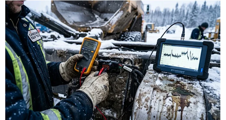
Use a multimeter with millivolt resolution — a Fluke 87V or something comparable. Key on, engine off, all ECUs awake. Kill every accessory: lights, blower, radio, wipers.
Select two ECUs located as far apart as practical. The engine ECU and the cab instrument cluster are a solid pair. Probe between the J1939 ground pins at each connector — typically pin C on a standard 9-pin Deutsch diagnostic receptacle, or the dedicated CAN ground wire in the backbone harness. Many machines run an 18 AWG black wire in pin B or C, depending on connector series.
Record the DC voltage. Below 100 millivolts is acceptable. Above 200 millivolts tells you there’s a ground integrity problem even before any heavy loads come online. If it’s past half a volt, park every other diagnostic until this is resolved.
2. Map the offset under load
Start the engine. Note the offset. Cycle on the headlights, the HVAC blower at maximum, heated mirrors, the grid heater if it will engage, work lights — anything that draws real current. A healthy network might shift 50 to 80 millivolts. A compromised one will sail past 300 millivolts and keep climbing. I’ve recorded 2.3 volts on a machine where a three-quarter-inch rust blister had pushed the battery negative cable away from the frame rail. The offset spiked precisely when the grid heater pulled in.
If the offset jumps with a particular load, that load’s ground return path is implicated.
3. Scope the common-mode waveform
A meter gives you the average. A scope reveals the dynamic behavior. Connect an isolated oscilloscope — Channel 1 on CAN_H, Channel 2 on CAN_L, both referenced to that ECU’s ground pin. The differential trace may appear textbook, but switch the scope to display (CH1 + CH2) / 2: that’s the common-mode voltage . It should hover near 2.5 volts with gentle movement. I once traced a ground offset to a cooling fan whose brush arcing produced a 300-millivolt spike train on the common-mode trace at exactly 83.3 hertz — a four-pole motor turning at 1,250 RPM. The fan was blowing air. The operator had no complaints. The CAN bus was screaming.
Without an isolated scope, use a differential probe. Never float a bench scope. The damage isn’t worth the shortcut.
4. Isolate sections of the harness
Ground offset faults gravitate toward chafe points and connector bodies. Unplug backbone segments sequentially until the offset collapses. If there’s an accessible bulkhead connector, split the network there. If the offset vanishes on the engine side, the problem lives in the cab. If it persists, move toward the rear chassis harness.
Run a temporary dedicated ground wire — 14 AWG or heavier — straight from battery negative to the suspect ECU’s ground stud. If the offset drops to near zero, the original ground path is compromised.For intermittent opens that don’t show up under static voltage checks, a systematic wiggle test protocol can localize the exact harness section before you start disconnecting connectors.
5. Verify the shield is grounded only once
I recall a telematics installation where the shop had grounded the shield at both the cab bulkhead and the rear termination resistor, convinced that “more grounding is better.” That loop captured alternator whine with impressive efficiency. Unscrewing one end dropped the common-mode noise from 470 millivolts peak-to-peak to 32. J1939-15 mandates a single-point shield ground for precisely this reason. Disconnect both network ends and measure shield continuity to chassis. Continuity at both ends confirms someone bonded both sides. Trace the harness and eliminate the extra connection.
6. Check for DC leakage from sensor circuits
A failing sensor or pinched sensor wire can inject voltage into an ECU’s analog input, pulling the internal ground reference off level. If a particular ECU shows high offset only with its sensor connectors mated, disconnect every sensor from that ECU and remeasure. I once found a coolant level sensor with an internal short pushing 4 volts onto the sensor return line. The ECU’s ground circuitry compensated, dragging its CAN reference upward by nearly a volt.
Five mistakes that keep technicians chasing their tails
- Measuring only resistance, never voltage. I watched a technician measure sixty ohms three times during a no-start — once with a beat-up Fluke, once with a borrowed meter, once while the supervisor observed. He never placed a voltmeter between ECU grounds. The offset was 1.9 volts the entire time. Four hours proving the termination resistors were fine while the network remained deaf.
- Adding extra ground straps without thinking. A braided strap from an ECU case to the frame can mask a ground offset symptom but simultaneously create a new ground loop that couples EMI into the two-way radio. Repair the original ground path instead of layering on parallel conductors.
- Cleaning connector pins and calling it fixed. The Deutsch connector internals looked factory-fresh. But the bolt securing the ECU bracket to the frame rail had sheared off months earlier. The bracket was grounding through a paint edge — cold mornings, it made contact. By midday, thermal expansion broke the connection. The connector was collateral damage, not the cause.
- Assuming the network ground wire is present and correct. Some harnesses omit the dedicated CAN ground wire, depending on the power ground return to carry the reference. That might survive in a passenger car that never sees road salt. On a drilling rig in northern Alberta, it won’t. Open the backbone and physically confirm the ground wire runs end to end, matches the SAE J1939-15 gauge specification, and is properly terminated at both sides.
- Believing a new component eliminates the problem. A replacement ECU arrives with pristine ground pins and clean internal references, temporarily hiding an offset that’s still present. Six months and one winter later, after the new connector has endured salt spray and vibration, the ghost reappears. The fault was always embedded in the harness.
Knowing the repair is good
Cleared fault codes don’t prove a solid ground reference. You need measured confirmation.
Using the same static test configuration, a healthy J1939 network should exhibit:
- DC offset between any two ECU ground pins (key on, engine off, no loads): under 100 millivolts.
- DC offset with engine running, every load engaged: under 200 millivolts, stable, no spikes.
- Common-mode voltage on a scope: centered at 2.5 volts, peak-to-peak deviation less than 500 millivolts during worst-case electrical load.
- Zero new CAN frame errors after one complete operational cycle — most diagnostic interfaces tally transmit and receive errors per node. After a cold start through a full heat soak, no new errors should appear.
One final field check: operate the machine aggressively with every high-current circuit active while capturing a J1939 trace for ten minutes. Feed that trace through a parser. A single stuff error, form error, or acknowledgment error in those ten minutes is one too many.
Hardware that makes diagnosis repeatable (instead of guesswork)
I’ve spent too many hours holding multimeter probes inside Deutsch connectors during rainstorms to undervalue tools that remove variables. That’s the same reason our factory has spent over twenty years producing diagnostic interfaces and custom J1939 harnesses for OEMs and independent service centers. When a ground offset is intermittent and you’re against a deadline, a test cable that faithfully preserves impedance, shielding, and ground continuity is not a luxury. It’s the difference between capturing the real fault and measuring an artifact of your own test leads.
Our diagnostics breakout adapters are manufactured to SAE J1939-15, with shielded twisted-pair construction, sealed Deutsch or Ampseal connectors, and every ground pin verified with a milliohm meter under load before shipment. Every harness undergoes a live CAN traffic test — not as a marketing formality, but because we once caught a batch where the shield drain crimp was mechanically intact yet exhibited a 40-milliohm impedance bump at 500 kbps only when the cable reached operating temperature. Without that dynamic test, those cables would have sailed through continuity and hipot checks and later produced ground offset symptoms on a customer’s combine harvester.
The production facility holds IATF 16949, ISO 9001, and ISO 14001 certifications. Each assembly passes four inspection gates: continuity, hipot, shield integrity, and the live CAN traffic test. The floor operates under 5S discipline, storage is climate-controlled, and all components meet RoHS standards with UL and CE listings where applicable.
We don’t run an e-commerce storefront with a shopping cart. Instead, we sit down with your engineering group, examine your machine’s electrical topology, and build a test harness or backbone cable to your exact specification — connector clocking, wire gauge, jacket compound, logo, overall length. Whether you’re an OEM needing to replicate an intermittent ground offset fault for a validation run, or a fleet maintenance manager who wants a repeatable diagnostic setup that doesn’t introduce its own gremlins, it’s a conversation worth starting.
Questions I get asked about J1939 ground offset
What’s an acceptable ground offset voltage on a J1939 network?
Keep it under 200 millivolts with all loads active. SAE J1939-15 doesn’t publish a single hard threshold for offset, but CAN transceiver common-mode limits demand headroom. At 500 millivolts, schedule corrective work. At one volt, take the machine out of service. Even a small 0.3V ground offset can accumulate significant fleet costs over time.
Can ground offset damage an ECU?
Absolutely. Persistent common-mode voltage beyond the transceiver’s absolute maximum rating degrades the receiver input stage over time. A three- or four-volt offset can permanently damage the CAN transceiver chip with no visible burn marks. I’ve seen ECUs that passed a bench diagnostic but failed on the machine because their receiver front-end was compromised.
Why does ground offset produce intermittent faults rather than hard failures?
Because the offset magnitude varies with electrical load, temperature, and vibration. A borderline offset only becomes a hard fault when a high-current accessory switches on or a chassis connection heats up and increases its resistance.
Does CAN bus termination resistance affect ground offset?
It has an indirect effect. An incorrect or missing termination resistor alters the differential voltage swing and shrinks the noise margin. Combined with a ground offset, the receiver faces a signal that’s both attenuated and shifted outside its valid common-mode window. The two issues reinforce each other.
Can I measure ground offset with a standard OBD scanner?
No. Generic OBD scan tools display trouble codes and parameter data. They don’t expose physical-layer voltages. You need a multimeter and, ideally, an oscilloscope. Some professional-grade J1939 interface adapters provide dedicated common-mode measurement terminals for exactly this purpose.
I measured zero offset between two ECUs, but my scope shows huge common-mode noise. How is that possible?
A DC voltmeter averages the reading. If AC ripple from an alternator, a PWM fan controller, or a switch-mode supply rides on the ground, the meter may indicate zero DC offset while the peak common-mode swing destroys signal integrity. Switch the scope to AC coupling to see the noise the meter is hiding.
Why did my ground offset appear only after we pressure-washed the machine?
Water penetrated a connector that was sealed adequately against dust but not against a directed spray. The moisture formed a high-resistance path between the CAN ground and chassis, but only while the connector body remained wet. By the time you opened it for inspection, it had dried and looked fine. If the fault correlates with washing or heavy rainfall, replace the connector seals and fill the backshell with dielectric grease before blaming anything else.
Can I use the chassis as my CAN ground reference during a quick test?
You can, but your measurement will include the offset plus any voltage difference between your chosen chassis point and the ECU’s true ground reference. The number becomes an estimate. For a measurement you’d stake a repair on, always probe the actual ground pin at each ECU. Chassis steel is not a precision voltage reference.
What if my harness has no dedicated CAN ground wire?
Some older systems rely on the power ground return to establish the reference. That approach is brittle in high-vibration environments. When designing or refurbishing a harness, add a dedicated 18 AWG CAN ground wire that bonds all module grounds and ties to battery negative at a single point. SAE J1939-15 strongly recommends this.
Is ground offset more prevalent on 24-volt equipment?
Yes. Higher supply voltage tolerates larger voltage drops across degraded connections before circuits stop operating, so a one-volt offset is more likely to go unnoticed on a 24V machine than on a 12V one. The CAN transceiver, however, still operates at 5 volts and suffers just the same.
Should the CAN shield be connected at both ends?
No. Terminate the shield at one end only, typically at the termination point closest to the battery. Bonding both ends forms a ground loop that captures magnetic noise and superimposes an AC component onto the common-mode voltage. I’ve watched a single extra shield ground convert a reliable network into a message error generator.
Can a failing alternator produce a ground offset?
Yes. A diode with high leakage or a deteriorated slip ring can inject AC ripple into the chassis ground. I diagnosed one ground offset that manifested only above 1,600 RPM. The alternator had a cracked brush holder that vibrated at that specific engine speed.
After I repair the ground fault, how long should I monitor the network?
Run the machine through two complete thermal cycles — cold soak to full operating temperature and back down — while logging CAN traffic. If the error counters stay at zero and the offset remains stable throughout both cycles, the repair is permanent.
Every ground offset case carries its own signature, but the underlying physics is unchanging. A network that cannot agree on what ground is cannot agree on what a message says. When a machine behaves in ways that contradict every wiring diagram, set the pinout chart aside, pick up the multimeter, and measure what the electrons are actually seeing. The answer frequently sits right between two ground pins.
If you’re fighting a problem that ignores every textbook fix, or you need a diagnostic harness that won’t add its own unknowns to the measurement, we’ve spent two decades helping fleet managers and OEMs resolve exactly these frustrations. Reach out directly on WhatsApp or through our contact page. No catalogs, no shopping carts — just an engineering conversation about the problem you’re solving and whether we can build something that contributes.