

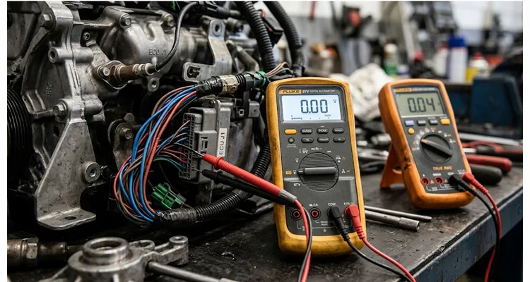
I spent a frustrating Tuesday afternoon in 2019 chasing an electrical ghost on a Euro 6 diesel bench harness. The symptom was a sporadic P0106—MAP sensor range/performance—that only appeared when the engine bay heat-soaked. The sensor was new. The wiring was new. The 5V reference was spot on.
The problem was my multimeter. Not the sensor, not the harness, not the ECU—the tool in my hand was injecting an error I never asked for.
I was using a perfectly good, mid-tier True RMS multimeter. When I back-probed the sensor ground wire at the ECU connector, I read 0.04V with the key on, engine off. That is a classic ground offset reading. It is enough to make you tear the loom apart looking for corrosion.
Then I grabbed the lab Fluke 87V, stabbed the same two pins, and read 0.00V. The engine harness was fine. The first meter was lying to me.
I have watched identical sensor circuits give different readings just because I swapped test gear. The first time it happened, I wasted four hours stripping a harness that was never bad. Let me walk you through the bench test that finally nailed down this multimeter input impedance trap.
The Moment You Realize the Multimeter Input Impedance is Part of the Circuit
Most technicians treat a voltmeter like a window into the circuit—something that shows you the voltage without touching anything. That assumption breaks down the moment you start probing sensor grounds.
When you connect a meter to a circuit, you become part of that circuit. The input impedance of the meter—whether it is one million ohms or ten million ohms—determines how much current you are stealing from the circuit to make your measurement.
If you are measuring across a flooded lead-acid battery, the difference between a 1MΩ meter and a 10MΩ meter is mathematically invisible. The battery can supply hundreds of amps, so a few microamps of meter loading vanish into the noise.
But a sensor ground inside an engine bay is a completely different animal from a battery post. These are low-current, high-precision return paths. An ECU’s analog-to-digital converter is looking at a differential voltage that may only swing a few millivolts. When you stick a low-impedance probe into that circuit, you alter the voltage divider.
Why Pull-Up and Pull-Down Circuits Suffer First with Multimeter Input Impedance
This is especially brutal on pull-up and pull-down circuits. If you are trying to measure the low state of an open-collector sensor through a 1MΩ meter, the meter’s internal resistance is often low enough to act as an alternate current path. It drags the signal down—or up—relative to what the ECU actually sees.
On our production floor, we see this most often when a customer tries to validate a cam sensor signal with a cheap meter before connecting a scope. The cheap meter loads the open-collector driver, and the ECU loses the edge it was looking for.
The ECU has its own internal impedance. When you add your meter in parallel, you are changing the effective resistance of that node. The ECU might be perfectly happy with the signal. Your meter just made it look broken.
Root Cause: The Math Behind the Lying Reading and Multimeter Input Impedance
Let’s break down exactly why a 1MΩ meter shows 0.04V on a healthy sensor ground when a 10MΩ meter shows 0.00V.
A sensor ground return path is never a zero-ohm wire, even when the wiring diagram says it is. It is a network of terminals, crimps, PCB traces, and wires. Even a healthy harness has some electrical resistance. Let us say a particular ground return trace on an ECU board has a resistance of 4Ω—four ohms.
When the ECU powers up the sensor, it draws a tiny amount of current on that ground leg. Let us say it is 0.01A—ten milliamps.
Using Ohm’s Law, V = I × R:
0.01A × 4Ω = 0.04V.
That is your theoretical real voltage drop across that specific trace. Good.
Now, connect a 1MΩ—one million ohm—multimeter from that point to chassis ground. We have just created a parallel resistor scenario.
The math for parallel resistance is (R1 × R2) / (R1 + R2):
Total Resistance = (4Ω × 1,000,000Ω) / (4Ω + 1,000,000Ω)
If we do the math, the total resistance drops to 3.999984Ω. That is virtually unchanged.
So why did the meter read 0.04V with the key on? Because the 1MΩ meter was not measuring the voltage drop across the trace. It was measuring the supply current trying to overcome the meter’s internal resistance and the trace’s capacitance. The meter draws current—usually nanoamps to microamps. This current, however small, has to be supplied by the ECU driver. In a high-impedance monitoring circuit, even a nanoamp of leakage can pull the reference voltage down if the source is capacitive.
A 10MΩ meter draws ten times less current than a 1MΩ meter. If the 1MΩ meter requires 1µA—one microamp—to register a reading, and the circuit’s source impedance is high, say 50kΩ, the voltage drop across that source impedance caused by the meter itself is:
V = I × R
V = 0.000001A × 50,000Ω = 0.05V.
You are seeing a voltage that you created by plugging in the meter. On the bench, we call this pulling the signal down. The official term is circuit loading error, but it feels more like the meter is leaning on the wire.
The 10MΩ meter only draws 0.1µA. The loading error drops to 0.005V—negligible.
The Sensor Ground Drift: A Step-by-Step Lab Example
Let me show you the exact bench setup I use to demonstrate multimeter input impedance to new engineers on our production floor. We build OBD diagnostic cables and breakout boxes for a living, so we see this daily.
You do not need a car to prove this. You need a bench power supply, a resistor, and two meters.
Step 1: Build a High-Impedance Source for Multimeter Input Impedance Testing
Grab a 1MΩ resistor from the bin. Solder it to a piece of scrap harness wire. Connect the other end to a 5V supply. The free end of that resistor is your test point—nobody touches it with bare fingers, because skin oil is enough to change the reading.
Step 2: Measure with the 1MΩ Meter to See Multimeter Input Impedance Effect
Connect the 1MΩ meter from the test point to ground. You will likely read around 2.5V. Not 5V. Why?
Because the 1MΩ resistor—the source—and the 1MΩ meter—the load—form a perfect 50/50 voltage divider. The meter is cutting your voltage in half.
Step 3: Measure with the 10MΩ Meter to Compare Multimeter Input Impedance
Swap to the 10MΩ meter. You will read 4.5V to 4.6V.
This is much closer to the truth. The 10MΩ load is so high relative to the 1MΩ source that it barely drags the voltage down.
Step 4: Apply Multimeter Input Impedance Knowledge to a Car Sensor Ground
In a car, the wiring harness is rarely as bad as a 1MΩ resistor. But when you are checking the bias voltage on a knock sensor or the reference line of a thermistor, the source impedance is extremely high.
If you use a 1MΩ meter, you are effectively placing a wet finger on the signal line. The ECU might be seeing 2.5V, but the 1MΩ meter tells you it is 1.8V. You will chase your tail trying to find a wiring fault that does not exist.
Where the 1MΩ Meter is Actually Useful
I don’t want to trash the 1MΩ meter entirely. It has its place on the bench.
If you are working on a 480V motor drive or checking for voltage on a long run of conduit, the 1MΩ input is actually your friend. It bleeds off the phantom voltage that a high-end meter will happily display as live.
High impedance meters can read ghost voltage—voltages that exist only because of capacitive coupling between adjacent wires in a conduit. A 1MΩ meter, or even lower like a LoZ mode on a Fluke, will bleed off this ghost voltage and show you the true potential.
In automotive work, specifically on AC ripple tests on alternators or starter cranking voltage, the 1MΩ meter is fine because the current supply is enormous.
The issue only arises when you are measuring low-power, high-precision analog signals—exactly the kind you find on modern sensor grounds.
Common Mistakes That Make You Doubt Your Tools with Multimeter Input Impedance
I keep a list taped to the inside of my toolbox lid. It is a reminder of the mistakes I have made chasing impedance ghosts. Here is the short version.
Mistake 1: Trusting the Relative Function with Multimeter Input Impedance
You zero the meter leads, then probe a sensitive circuit. The meter might zero out the lead resistance, but it cannot zero out its own input impedance. On a 1MΩ meter, the zero drifts as the internal temperature of the meter changes.
Mistake 2: Using Cheap Back-Probe Pins on Sensor Grounds
A dull, thick back-probe damages the connector seal. Once the seal is damaged, moisture wicks in, and six months later the customer has a green crusty pin. That causes a real voltage drop that even a 10MΩ meter will read. The tool did not lie; the technician broke the connector.
Mistake 3: Comparing a Scan Tool Reading to a Multimeter Reading
The scan tool is reading the digital interpretation of the ECU’s ADC. The multimeter is reading the raw average voltage. The ECU has filtering algorithms. The meter does not. You cannot expect them to match perfectly, especially on PWM signals. Averaging a PWM signal with a meter depends on the meter’s bandwidth and input impedance.
Mistake 4: Ignoring the Battery in the Meter Affects Multimeter Input Impedance
It sounds too stupid to matter, but a dying 9V battery inside a DMM drifts the internal reference. The meter reads 12.6V on a stable supply, but it is guessing. A 10MΩ input impedance is only stable if the internal reference is stable. If your meter flickers or the backlight dims, change the battery before diagnosing a sensor fault.
Mistake 5: Using Alligator Clips Instead of Piercing Probes for Sensor Ground Testing
Long leads and alligator clips act as antennas. They introduce noise into the high-impedance measurement. The capacitance of the lead itself can cause the meter to read a pulsing signal as a steady high voltage.
How to Verify a Real Sensor Ground Problem, Not a Meter Artifact
So, how do you know if you are looking at a real wiring fault or a meter loading problem? Use the Parallel Resistor Trick. This is a trick I teach every apprentice before they touch a customer’s car.
If you suspect you are being fooled by ghost voltage or a high-impedance source, follow these steps:
- Take your reading. Note it down.
- Connect a known load—say, a 100kΩ or 1MΩ resistor—in parallel with your meter probes.
- Read again.
If the voltage drops significantly—say, from 2.5V to 0.5V—the circuit is high-impedance. The voltage you were reading could not supply any real current. It was likely a ghost voltage or a biased input. The 1MΩ meter was misleading you.
If the voltage stays the same, the circuit is robust. You have a real reading, and the problem is likely elsewhere—a logic issue in the ECU, a timing issue, or a bad sensor element.
This trick takes thirty seconds and saves you from stripping a wiring loom.
The Factory Reality: Why We Build for Multimeter Input Impedance Tolerance
We have a shelf in the R&D corner with every meter you can think of: a fifty-dollar hobby unit, a mid-range automotive meter, and a scope meter that costs more than a used hatchback. We test our breakout cables with all of them. If a cable behaves differently on the cheap meter than on the scope, we do not ship it.
Why Contact Resistance Matters More Than Multimeter Input Impedance
If the contact resistance of a pin is high, it does not matter if you have a 10MΩ meter; you will read a voltage drop that exists physically inside the connector. The meter is just reporting the truth.
That is why we run 4-step quality inspection on every cable we produce. We do a continuity test, but more importantly, we do a milliohm resistance test on the ground circuits. A ground wire that measures 0.2 ohms on the bench is okay. A ground wire that measures 2.0 ohms is going to cause drivability issues when the customer back-probes it with a high-impedance meter. This is exactly the kind of fault we cover in our guide to crimp resistance drift and 100mV ground offset.
Salt Spray and the Real World of Sensor Ground Corrosion
We also treat the materials. The environment destroys high-impedance circuits. We run salt spray tests on our connector housings to ensure that the seal integrity holds up. Because once salt water gets into that ground pin, the electrochemical corrosion creates a real, physical resistance. That creates the exact same symptom as the lying meter—but this time, it is actually a bad wire.
Documentation for Tier-One Clients and Multimeter Input Impedance Validation
For clients in the US and European markets, we also supply PPAP—Production Part Approval Process—documentation. This is crucial. If you are a tier-one supplier diagnosing a fleet issue, you need to know that the harness you are testing has been validated. You cannot diagnose a meter mismatch if you are also fighting a manufacturing tolerance problem in the cable.
We hold IATF16949 and ISO 9001 standards, not just for the paperwork, but because when an engineer is measuring a 50mV signal, a 10mV offset caused by a bad crimp in a test lead is unacceptable.
Why Your Choice of Meter Input Impedance Dictates Your Diagnostic Strategy
Let us break down the practical workflow.
If You Only Have a 1MΩ Meter: Multimeter Input Impedance Workflow
- Do not attempt to measure floating sensor grounds directly. You will chase ghosts.
- Measure the voltage drop across the ground side under load. Disable the fuel pump so the car does not start, then crank the engine. Have a helper watch the meter while you wiggle the harness. If the voltage jumps, you have a loose crimp.
- Use the min/max function to catch transients. The 1MΩ impedance is fast enough to see dropouts.
If You Have a 10MΩ Meter: Multimeter Input Impedance Workflow
- You can trust your static voltage readings on sensor returns. The math works in your favor.
- But you need to be careful about ghost voltages on long harness runs that are not connected to anything. Use the Low-Z mode if you have it to drain capacitance.
Comparison: Diagnostic Scenarios and Multimeter Input Impedance Behavior
Here is a quick reference table I keep on the wall of the test bench. It helps the junior guys understand why we pick certain tools.
| Diagnostic Task | Circuit Source Impedance | 1MΩ Meter Reading | 10MΩ Meter Reading | The Truth | Winner |
| Battery Voltage | Very Low, under 1Ω | 12.60V | 12.60V | 12.60V | Tie |
| Alternator Ripple, AC | Low | 0.25V AC | 0.25V AC | 0.25V AC | Tie |
| O2 Sensor Bias, Pump Cell | Medium | 0.45V erratic | 0.45V stable | 0.45V | 10MΩ for stability |
| MAP Sensor Ground | High | 0.04V | 0.00V | 0.00V | 10MΩ |
| Knock Sensor Bias | Very High | 1.8V | 2.5V | 2.5V | 10MΩ |
| Disconnected Wire, Ghost | Infinite | 0.0V drains | 12V floats | 0V no connection | 1MΩ or LoZ |
Note: The Ghost Voltage row is why you should never use a 10MΩ meter to check for presence of voltage on a disconnected harness connector. It will pick up static from the air and tell you the wire is hot when it is not. Here, the 1MΩ is superior.
Real Questions I Get From Technicians
These are not textbook FAQ entries. These are the questions that land in my inbox and on the shop floor.
I mostly work on trucks. Should I just buy the most expensive meter?
Not if you are only checking battery cables and alternator ripple. The 10MΩ input is only critical when you are probing things like CAN bus transceivers, sensor returns, or ECU reference pins. For heavy-current stuff, a basic meter with a LoZ function will save you from ghost voltage headaches.
Why does my scan tool show a different voltage than my multimeter?
The scan tool is reading the value after the ECU has filtered it. The multimeter is reading the raw average voltage. The ADC in the ECU has an internal impedance that is often much lower than 10MΩ—sometimes 100kΩ. So the ECU itself loads the circuit. You are comparing an engineer’s view to the computer’s view. For more on this, see our breakdown of single-ended vs. differential ADC MAP sensor readings.
Can I damage a car by using a 10MΩ meter?
No. The current flow is so microscopic—nanoamps—that you cannot blow a fuse or damage a driver. You can, however, cause a car to stall if you are probing a delicate communication line like CAN bus high/low with a set of very long, unshielded leads. The added capacitance of the 10MΩ meter’s leads can distort the square wave and drop the network. Use short leads.
I bought a meter from a hardware store. It does not say anything about impedance. Now what?
Assume it is 1MΩ. Even if it claims True RMS, the input loading is probably the cheapest 1MΩ network they could fit on the PCB. If you are doing sensor work, you need to look for 10MΩ printed near the voltage input jacks or in the spec sheet. If it is not there, it is not there.
Does lead resistance matter more than input impedance?
For current measurements in amps, lead resistance is critical. For voltage measurements on sensors, lead capacitance matters more than resistance. A cheap set of test leads can have enough capacitance to filter out a fast PWM signal, making the meter read a lower voltage than what is actually there.
What is ghost voltage and how do I stop it?
Ghost voltage is a voltage induced by magnetic or electric fields in parallel wires. A 10MΩ meter is sensitive enough to see it. It looks like a real voltage, but it collapses as soon as you put a load on it. Use the LoZ or Auto-V LoZ setting on a Fluke to eliminate it. This internally puts a low resistance in parallel to the test leads, bleeding the ghost voltage off.
Why did my car run fine before, but after I probed it, it started running rough?
You likely damaged the terminal. A test probe tip can easily spread a female terminal in a connector. When you unplug the meter, the pin remains loose. The result is a high-resistance connection—precisely the problem you were trying to find. Always use the correct back-probe tips and never force a probe into a female connector.
Does temperature affect the meter’s input impedance?
Yes. Input impedance drifts with temperature. In the cold, the resistors have a different value than when hot. If you zeroed the meter in the morning and are testing in the afternoon sun, trust the Relative function less. Always let the meter acclimatize to the engine bay temperature for five minutes before taking critical millivolt readings.
I am building a test bench. Which meter should I buy for ECU work?
You need a bench multimeter with at least 10MΩ input impedance and a fast min/max capture rate. You also need to invest in quality breakout harnesses. If your bench harness has poor shielding or cheap wire, it does not matter which meter you buy. The harness will introduce the noise. A good starting point is our guide on test bench OBD cable AWG loop resistance and ground separation.
Does the input impedance change when I switch to AC mode?
Yes. The input impedance for AC voltage is often lower and is tied to frequency. When measuring a sensor that produces an AC signal like a VR crank sensor, the 1MΩ versus 10MΩ difference becomes frequency-dependent. At high frequencies, the meter’s impedance drops, which can clip the signal amplitude. This is why oscilloscopes are preferred for AC sensors—they have a 10MΩ impedance with a known, compensated capacitance.
What This Means for Your Test Bench
The difference between a 1MΩ and a 10MΩ meter often comes down to the quality of the equipment between the ECU and the sensor. If you are building a diagnostic rig, a calibration setup, or a fleet maintenance cart, the integrity of the harness is the only thing that allows the meter to tell the truth.
We manufacture OBD breakout cables, ECU extension harnesses, and sensor test leads for clients who need to know that their readings are exact.
OEM Customization Without the Runaround for Multimeter Input Impedance Test Benches
We can customize the length, color, AWG—wire gauge—and connector brand to match your specific diagnostic bench. You tell us what you are testing, and we build the harness around that application, not the other way around.
Engineering Support That Answers the Phone for Sensor Ground Issues
If you are struggling with a specific harness layout that is picking up noise, contact us. We can advise on shielding and pinout layout. We have seen the same interference patterns on our own bench, and we know which fixes actually work.
Quality Assurance You Can Audit for Multimeter Input Impedance Accuracy
We operate under IATF16949 and ISO 14001 standards. We use a 5S management system and a climate-controlled warehouse to ensure that the connectors and wires reach you in the exact condition they left the mold.
PPAP and Salt Spray Reports for Sensor Ground Validation
We provide PPAP level 3 documentation and salt spray test reports for high-end clients who require validation. If your customer demands evidence that the harness will survive, we can supply the paperwork to back it up.
If you are chasing a ghost voltage or a fluctuating sensor ground, the problem might not be in the car—it might be on your bench.
I have watched a good technician spend a full day replacing a sensor, a harness, and an ECU over a meter that was lying to him. Do not do that. Get your equipment sorted first, then blame the car.
If you need help specifying the correct harness for your diagnostic setup, reach out on WhatsApp. We are online during business hours, and we can help you pick the right pins, wire gauge, and shielding for your multimeter’s requirements.
If you already have a pinout and a spec sheet, visit our Contact Page and send us the details. We respond within one business day.
Sort out your bench first. The multimeter readings will take care of themselves.
