

This is the kind of fault that doesn’t show up on a bench test at twenty-five degrees Celsius. It shows up three weeks later, on a customer’s truck, at 6:40 in the morning, after a cold start, when the engine light comes on for a cam sensor that the dealer’s own tool never sees. If you build or resell diagnostic tools, this is worth the next fifteen minutes of your time.
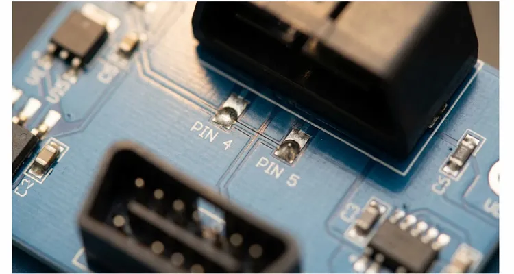
I have spent the better part of two decades looking at J1962 connector boards under a magnifier. Most of the tools that come back to our factory with intermittent CAN communication or ghost sensor codes share one small, almost invisible habit on the PCB: Pin 4 and Pin 5 are tied together with a ten-mil trace, a solder bridge, or sometimes just a single via that someone thought was harmless.
It is not harmless.
This article explains what Pin 4 and Pin 5 actually do inside a vehicle, why shorting them inside your dongle or handset creates problems that no firmware update will ever fully fix, and how to check a tool you are about to sell—or the one you are about to buy.
A Fault That Looks Like a Software Problem
Here is a typical call I get from an importer or a fleet manager:
“The tool works fine on my desk. In the truck, it reads the VIN, then after twenty minutes the DPF differential pressure sensor starts reading nonsense. Sometimes the coolant temperature spikes to ninety-nine degrees for two seconds, then comes back. The truck is fine. The dealer says the sensor is fine. Your tool is lying.”
The customer assumes firmware. Nine times out of ten, the firmware is innocent. The ground plane is not.
When a diagnostic tool intermittently reports sensor values that the vehicle’s own modules do not consider faulty, the first thing I ask is: “Open the enclosure. Show me the ground plane near the J1962 footprint. Are Pin 4 and Pin 5 tied together?”
The pause on the other end of the phone usually gives me the answer before the photo does.
What J1962 Pin 4 and Pin 5 Actually Do
The SAE J1962 connector is physically standardized, but electrically it behaves less like a single sixteen-pin D-shell and more like two separate ground systems that happen to share a plastic housing. Pin 4 and Pin 5 are both called “ground” on a lot of cheap datasheets. That word, ground, is doing a lot of dangerous work. The two pins are not the same node, and vehicle manufacturers do not treat them as interchangeable.
Pin 5: Signal Ground
Pin 5 is the signal ground—the reference your K-Line or L-Line transceiver measures against. On a Toyota with a K-Line ECU, that reference is supposed to be quiet. On a truck with a J1850 VPW bus, the same pin is the only thing keeping a seven-volt pulse train from looking like noise.
In a well-designed scan tool, Pin 5 should be a return path that carries only transceiver currents. It should connect to the tool’s internal logic ground through a controlled path, and it should never share copper with relays, backlights, buzzers, or charging circuits.
Pin 4: Chassis Ground
Pin 4 is chassis ground—the vehicle body, the engine block, the alternator case. It is not quiet. On a running vehicle, chassis ground carries the return currents from injectors, ignition coils, alternator rectifier ripple, wiper motors, and a dozen other noisy loads. The voltage difference between Pin 4 and Pin 5 can easily be a few hundred millivolts of AC ripple at idle, and it moves constantly.
Some manufacturers bond Pin 4 and Pin 5 at the ECU with a filtered connection. Some do not. The J1962 specification gives manufacturers latitude precisely because the two pins serve different purposes on different protocols.
When you short Pin 4 and Pin 5 inside your diagnostic tool, you are not creating a better ground. You are creating a new, unfiltered path that lets chassis noise flow directly into the signal reference plane of your tool’s transceivers.
What Happens Electrically When You Bond Them
Let me be more precise, because this is where most online forum advice falls apart.
The transceiver’s ground reference
Inside a diagnostic dongle, the communication ICs—whether an ELM327 clone, an STN1170, an MCP2515 CAN controller, or a fully custom ARM-based platform—need a clean local ground to compare incoming signal voltages. A CAN transceiver decides whether a bit is dominant or recessive based on a differential voltage between CAN_H and CAN_L. That decision is immune to common-mode ground shifts up to a point. The datasheet says that point is usually minus two volts to plus seven volts relative to the transceiver’s ground pin.
The alternator is not a pure DC source
Now consider what happens when the tool’s ground is tied to chassis ground through Pin 4. The alternator produces a three-phase rectified ripple, typically in the hundreds of hertz to several kilohertz range, depending on RPM and load. Injector solenoids and ignition coils create fast, high-energy transients. The vehicle’s chassis ground bounces relative to the ECU’s signal ground by several hundred millivolts under normal operation, and by several volts during engine cranking or when a heavy inductive load switches off.
When Pin 4 and Pin 5 are bonded inside the tool, that entire transient appears directly across the ground reference of your transceiver. The differential CAN bus may still look fine on a benchtop, but the moment the ground reference dances, the receiver’s decision threshold dances with it. The tool starts seeing bit errors on the bus. The protocol stack retries. The retry floods the bus with error frames. The vehicle’s ECU starts logging U-codes—communication fault codes. On some platforms, the ECU’s own fault management then flags sensor plausibility checks as questionable.
What does the technician see on the screen? Not a clean “communication error.” He sees a DPF differential pressure reading that is suddenly out of range. He sees an EGR valve position that does not match the commanded duty cycle. He sees a phantom coolant temperature spike. These are not real sensor failures. They are the ECU’s fault management struggling to reconcile plausible but borderline data during a period of bus instability caused by the scan tool itself.
A controlled test in our lab
I have reproduced this in our own lab with a function generator and a grounded bench harness. Two identical firmware builds. One tool with Pin 4 and Pin 5 separated, one with them tied. The separated tool reads three hundred frames clean. The tied tool shows intermittent invalid SID responses on J1979 service 0x01 after roughly fifteen minutes of simulated alternator ripple at two hundred millivolts peak-to-peak. Same firmware. Same vehicle simulator. The only difference is a single solder bridge.
Why “It Works on My Bench” Is Not a Test
This is the argument I hear from tool resellers who have a box of samples that all power up and read the VIN on a workbench. A bench setup almost always has a clean lab power supply, a short ground lead, and a known-good simulator. There is no alternator ripple, no injector transient, no worn chassis ground strap, no aftermarket LED light bar sharing the same ground reference. The bench is a controlled ecosystem. The vehicle is not.
A diagnostic tool that spends its entire life on a bench is not a diagnostic tool. It is a development reference. The product you ship has to survive the electrical reality of a ten-year-old truck with a tired alternator and a customer who just jump-started it in the rain.
The Real-World Consequence: Fault Codes That Cost Money
Let me give you a concrete example, because this is the part that matters for anyone selling or supporting these tools commercially.
A customer in the Australian mining sector reported that a certain batch of heavy-duty scan tools was triggering “Camshaft position sensor – intermittent” codes on a specific model of haul truck. The trucks were fine. The dealer tool read nothing. The customer’s tool triggered the code roughly once every two hours of operation. The tool manufacturer blamed the truck. The truck manufacturer blamed the tool. The customer was caught in the middle and nearly lost a service contract over it.
We received two of the suspect tools at our factory. The J1962 connector board on both units had Pin 4 and Pin 5 connected through a ground flood on the top layer. There was no schematic note, no silkscreen marking. The designer had simply poured a copper region around the J1962 pads and tied everything to the same net. It worked in prototyping. It passed a bench test. It failed in the field.
We re-spun the board with Pin 4 and Pin 5 isolated, with a dedicated signal ground pour connected to Pin 5 only, and with a common-mode choke and a bidirectional TVS on the single-ended lines. The phantom cam sensor code disappeared. The customer kept the contract. The original vendor never knew why their tool was blamed. That is the cost of a ten-mil trace.
How to Check Your Own Tool in Ten Minutes
If you have a diagnostic tool in your hand right now, or if you are evaluating a factory’s tool before signing a purchase order, do this before you do anything else. You do not need a spectrum analyzer or a four-channel scope. A decent multimeter and a strong light will tell you most of the story.
Step 1: Unplug everything and remove the enclosure
Power the tool down. Remove the enclosure. Find the J1962 connector on the PCB. If the connector is a molded pigtail, follow the wires back to the board and identify the solder points for Pin 4 and Pin 5.
On a standard J1962 male connector viewed from the solder side, Pin 4 is chassis ground and Pin 5 is signal ground. Confirm the pin numbering from the J1962 standard—do not trust silkscreen labels alone, because many factories copy wrong labels.
Step 2: Measure continuity between Pin 4 and Pin 5 on the PCB
Set the multimeter to continuity or the lowest resistance range. Probe the solder pads for Pin 4 and Pin 5 directly. If you measure less than one ohm, the two pins are bonded somewhere on the board. That is the first red flag.
A properly designed tool may still have a high-impedance path between the two pins—for example, a ferrite bead with a parallel resistor, or a dedicated ground isolation network. But if it is a dead short, the designer has connected chassis and signal ground at the connector. You are now dealing with the noise path I described above.
Step 3: Look at the ground plane around the transceiver
Trace Pin 5 to the main ground plane. Ask yourself: does the transceiver IC’s ground pin connect to that same plane cleanly? Is there a dedicated ground pour under the CAN/K-line transceivers that does not merge with the high-current paths for the backlight, buzzer, or charging circuit?
On a good board, the signal ground pour under the communication ICs will have a clear, unbroken path to Pin 5 and will not carry the switching currents from other subsystems. On a bad board, the ground pour is one giant copper flood that merges everything.
Step 4: Check for a common-mode choke on the bus lines
For CAN, look for a small four-pin component near the J1962 connector with two coils—usually a common-mode choke. For K-line and L-line, check for a series resistor or a small inductor on the signal traces. A missing choke is not automatically a defect, but combined with a bonded ground it makes the tool far more vulnerable to bus noise.
Step 5: Power up on a vehicle and check for ground offset
If the tool has a pass-through or if you can probe safely, start the vehicle and measure the AC voltage between Pin 4 and Pin 5 at the vehicle’s diagnostic connector with the tool disconnected. You should see something—a few tens of millivolts up to a couple of hundred millivolts, depending on the vehicle. That is the electrical reality the tool has to tolerate. If you want to go deeper on J1939 ground offset diagnosis, we have a separate write-up on the measurement method and common failure patterns. If your tool’s internal design treats that offset as irrelevant by bonding the two pins, the tool will eventually show you symptoms.
Five PCB Layout Mistakes in OBD2 Scan Tools That Make Pin 4 and Pin 5 Bonding Worse
Over the years I have collected a mental list of board-level mistakes that turn a mildly questionable design into a genuinely failing product. If you see any of these on a sample from a prospective factory, do not sign the first production run. Ask for a new layout or find another factory.
1. The “one big ground pour” philosophy
The cheapest and fastest way to lay out a PCB is to pour a single ground region on both sides and drop every grounded component onto it. It works for a blinking LED. It does not work for a diagnostic tool that has to read serial data from a running vehicle. The ground pour becomes an antenna and a noise highway. Signal ground and chassis ground must have separate paths, with a defined, filtered connection point if any exists at all.
2. Bonding Pin 4 and Pin 5 with a zero-ohm jumper “for compatibility”
Some hardware engineers add a zero-ohm resistor between Pin 4 and Pin 5 so that the same board can be used for different vehicle protocols or different customer requirements. That jumper is almost always populated in production because the factory follows the BOM and puts a zero-ohm resistor everywhere the BOM says to. The result is a shipped product with Pin 4 and Pin 5 shorted. If you need a jumper, leave it unpopulated by default and document clearly when it should be filled.
3. Running the backlight or buzzer return through the signal ground
A diagnostic dongle with a bright blue status LED and a buzzer that draws tens of milliamps can pollute its own signal ground if those return currents share the same copper path as the transceiver ground. The noise is self-inflicted. The tool does not need a vehicle to have bad communication; it can degrade its own reference quietly, right on the bench.
4. Using “automotive grade” as a shield instead of a design input
An automotive-grade connector means the plastic won’t melt and the plating won’t corrode. It does not mean the circuit design is immune to ground bounce. I have seen tools with gold-flashed J1962 connectors and beautiful enclosures that failed in the field because the board inside was laid out like a hobbyist Arduino shield. The connector and the board are two different things.
5. Fixing the symptom with longer timeouts in firmware
When a tool reads intermittent data, the fastest software fix is to increase the timeout and retry count so that the tool recovers silently. That hides the problem from the user but does not remove the underlying ground noise. The customer still gets a slow, flaky tool. The phantom codes on the vehicle side still get logged. The firmware team gets blamed for a hardware problem.
How to Confirm the Fix Is Real
If you have redesigned a board or selected a new supplier’s tool, do not trust a bench test to confirm the ground problem is gone. Use a test that actually exercises the failure mode.
The ripple injection test
Connect the tool to a known-good vehicle simulator, then inject a controlled AC ripple between Pin 4 and Pin 5 on the harness side. I keep an old Leader function generator on the shelf for this. I feed it into a small audio transformer, secondary in series with Pin 4, ground on the other side. Start at fifty millivolts peak-to-peak at one kilohertz, then walk the frequency up while watching the tool’s bus traffic. A good tool will continue to communicate cleanly. A marginal tool will start logging errors.
This test is not part of most CE or FCC compliance runs. It is a design validation test. The tools that pass it are the ones that survive the real world.
The load-dump and cranking test
On a real vehicle, monitor the tool’s communication while cranking the engine. The starter motor pulls hundreds of amps, the battery voltage sags, and the ground offset between chassis ground and signal ground spikes. If the tool maintains communication through a cold crank, the ground design is probably solid. If it resets or drops the bus during cranking, you have more work to do.
The thermal soak test
Ground bounce problems are often worse at high temperature because trace resistance increases and the bond wire resistance inside the connector contacts shifts. Soak the tool in a forty-degree-Celsius chamber for an hour, then repeat the communication test. The tool that works at room temperature and fails at forty degrees is telling you something important about its margins.
What a Properly Designed J1962 Diagnostic Tool Looks Like Inside
Let me describe what I look for when I open a good diagnostic tool—the kind of tool a fleet manager can leave plugged in overnight without worrying about waking up to phantom fault codes.
The J1962 connector solders to a PCB that has two clearly separated ground regions. Pin 5 connects to a signal ground pour that surrounds the CAN controller, the K-line transceiver, and the microcontroller’s analog reference. Pin 4 connects to a separate chassis ground pour that terminates at the shield of the enclosure, if the enclosure has a shield, and is not used as the return for the logic circuits.
Between the signal ground and chassis ground, there is a defined connection—often a ferrite bead with a high-frequency impedance and a parallel one-megaohm resistor for DC reference. That network allows the two grounds to track each other slowly, so they never float more than a few hundred millivolts apart, but it blocks the high-frequency chassis noise from entering the signal ground.
The single-ended communication lines have series resistors. The CAN lines have a common-mode choke and bidirectional TVS diodes. The K-line has a current-limiting resistor rated for the full battery voltage. The power input has a reverse-polarity protection diode and a wide-input buck converter that does not pull its switching current through the signal ground.
Every grounded component on the board is placed so that its return current has the shortest possible path back to the correct ground region, not the nearest ground flood. The designer has clearly thought about where current actually flows, not just where the schematic says it goes.
That is the difference between a tool that reads a VIN on a bench and a tool that survives a mining haul truck.
Related Products: What We Build in Our Factory
I have used this article to describe a failure mode, but the same principles define the tools we manufacture at OBD-Cable. We are a direct factory with more than two decades of experience building diagnostic harnesses, connectors, and scan tool hardware for customers in Europe, North America, and Australia. Our tools cost more than the cheapest option because we do not buy reject connectors from a trading company and we do not skip the ground-isolation test. The cost difference shows up when a tool survives a cold crank in a haul truck.
Our J1962-to-open-end diagnostic harnesses are used by OEMs and aftermarket tool builders who need a connector pigtail that does not quietly short Pin 4 to Pin 5 inside the mold. We specify the wire colors and pin assignments clearly, and we test every batch for continuity and isolation before it leaves the factory.
For customers who need custom diagnostic dongles—whether a simple pass-through J1962 cable with an OBD-II male connector, a Y-splitter for bench programming, or a fully custom enclosure with your logo and firmware—we provide OEM support that includes board-level design review. If you send us a reference tool, we can open it, audit the ground layout, and explain exactly where the design is vulnerable. That audit has saved several of our customers from field failures they did not know they were about to ship.
Our production floor runs under ISO 9001 and IATF 16949 quality systems. Every batch goes through a four-step inspection process—incoming material, in-line function test, final assembly check, and a pre-shipment random audit. We use a 5S-managed production area with climate-controlled storage for connectors and sealed reels. All materials meet RoHS, CE, UL, and REACH requirements. When a customer asks for documentation, I pull the incoming inspection records, the in-line test log, and the pre-shipment audit sheet for their batch. The file exists before the question does.
If you are evaluating a diagnostic tool supplier, ask them one question before you ask about pricing: “Can you send me a photo of the inside of the tool, specifically the ground plane near the J1962 connector?” Most suppliers cannot. We can.
Frequently Asked Questions
Q1: My tool reads the VIN fine and then starts showing sensor faults after a few minutes of driving. Is that a Pin 4 / Pin 5 problem?
It is a strong candidate. The failure mode matches a ground reference that is moving with chassis noise. The tool may work fine during the initial connection when the bus is quiet, then degrade as the alternator loads up and the chassis ground bounces. Open the tool and check for continuity between Pin 4 and Pin 5. If it is a dead short, you have found the likely root cause.
Q2: Can a firmware update fix the phantom sensor faults caused by a bonded ground?
No. Firmware can hide the symptoms by increasing retry counts and suppressing intermittent fault logging, but it cannot remove the electrical noise from the ground plane. The noise is a physical property of the PCB. The only real fix is a board-level change.
Q3: What resistance value is acceptable between Pin 4 and Pin 5?
A dead short—less than one ohm—is a red flag. A properly designed tool may show a few hundred ohms or more, or a path through a ferrite bead that presents high impedance at AC frequencies. The exact value depends on the design, but a direct copper connection is almost never the right answer for a tool that reads single-ended buses like K-line.
Q4: Is it safe to bond Pin 4 and Pin 5 on a CAN-only tool?
CAN is differential, so the bus itself is more tolerant of common-mode ground shifts. But the transceiver still has a common-mode operating range, typically minus two to plus seven volts relative to its own ground. If the ground bounce exceeds that range during a load-dump or cranking event, the tool will still drop frames. Bonding the grounds does not help; it moves the problem into a range the transceiver cannot tolerate.
Q5: How do I identify Pin 4 and Pin 5 on a J1962 connector?
Look at the J1962 female connector on the vehicle. With the wide side on top and the pin rows facing you, the top row is Pin 1 through Pin 8 from left to right, and the bottom row is Pin 9 through Pin 16 from left to right. Pin 4 is the fourth pin on the top row, chassis ground. Pin 5 is the fifth pin on the top row, signal ground. On a male connector, mirror the assignment accordingly. Always confirm with the manufacturer’s datasheet for the exact physical component in your hand.
Q6: Does separating Pin 4 and Pin 5 cause problems on older vehicles?
Some older vehicles with unregulated charging systems have a larger offset between chassis ground and signal ground. If the tool’s input is designed with a reasonable common-mode range and a proper isolation network between the two grounds, it will handle that offset. Bonding the grounds to fix a large offset is like shimming a loose bearing with tinfoil. It hides the symptom and guarantees a different failure later.
Q7: My factory says they always bond Pin 4 and Pin 5 and their tools work fine. Should I push back?
You should ask for the schematic and the failure data. If a factory says their bonded-ground design works, ask them what happens during a cranking event with a load-dump on the alternator line. Ask for a test report. If they cannot provide one, the tool has not been validated against the full electrical environment it will encounter.
Q8: What is the most important test to run before approving a new diagnostic tool sample?
Connect the tool to a running vehicle, monitor the bus during engine crank and through a high-load alternator condition, and look for any communication dropouts or invalid frames. If that is not practical, use a bench setup with an injected ground-bounce signal between Pin 4 and Pin 5. A tool that passes the ripple test on the bench is likely to survive the vehicle.
Q9: Can a diagnostic tool with a plastic enclosure still have a signal ground problem?
Yes. The enclosure material has nothing to do with the internal ground topology. A plastic enclosure does not provide a chassis ground reference, so the entire tool floats relative to the vehicle unless Pin 4 and Pin 5 are connected. That makes the design decision inside the board even more critical: the tool must establish a safe ground reference without shorting the two vehicle grounds together.
Q10: What should I look for in a factory that builds diagnostic tools reliably?
Look for a factory that can provide board-level documentation, not just a datasheet and a sample. Ask for the ground plane layout, the transceiver circuit, and the test report from a load-dump or ground-bounce test. A factory that understands the Pin 4 versus Pin 5 issue is a factory that has been building tools for real vehicles, not just for sales samples.
If You Are Building or Buying a Diagnostic Tool, Let’s Talk
This article is not a sales pitch disguised as an engineering note. It is the honest account of a failure mode I have seen too many times in tools that should never have shipped. If you are a tool importer, a fleet manager, or an OEM looking for a hardware partner that understands ground planes, I am happy to walk you through what we do differently.
You can reach me directly through the contact page on our site. If you prefer a faster conversation, use WhatsApp and I will respond during our factory’s working hours. We provide OEM customization—your logo, your firmware, your cable lengths, your connector choices—and we support engineering customers who need more than a catalog part. If you have a reference tool in hand, send me a photo of the board inside the J1962 area. I will tell you within a few minutes whether you have a grounding problem waiting to happen.
Contact: Send us an inquiry via our contact page
WhatsApp: Chat with our factory team on WhatsApp
© OBD-Cable. All rights reserved. This technical note is based on our factory’s in-house failure analysis and design validation testing. Vehicle electrical environments vary; always validate any diagnostic tool against the specific vehicles in your fleet.
