

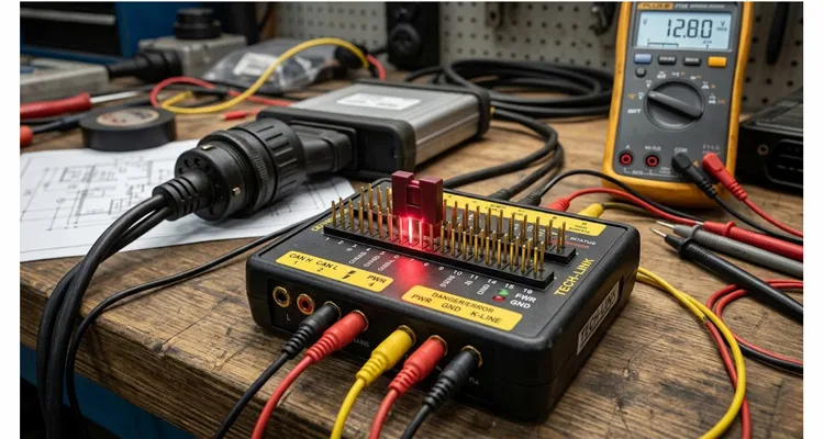
The 2016 Freightliner Cascadia rolled back into the bay two days after we replaced the engine control module. Same CAN bus failure. The new ECU was already dead. The breakout box on the floorboard still had the jumper across Pin 4 and Pin 5 from a bench test earlier that week.
We had tied chassis ground and signal ground together before the module ever saw them. The moment the key cycled, the five-thousand-dollar replacement unit took a hit it was never designed to survive.
If you run a mobile diagnostic truck, manage a fleet maintenance bay, or validate harness prototypes on an engineering bench, the jumper on your OBD2 breakout box is not a convenience feature. It is a configuration switch that changes the vehicle ground architecture. Get it wrong and you are not chasing codes anymore. You are ordering modules.
The jumper itself costs about two cents. The problem is what it does to the ground reference the moment you turn the key.
How a Pass-Through Box Becomes a Damage Path
A breakout box is supposed to be transparent. You plug the male end into the vehicle DLC, plug the scan tool into the female end, and back-probe the pins to see what the network is doing. The problem starts because not all breakout boxes are wired the same way. Some are straight pass-through. Others have configurable shunts so you can bench-test a component without a vehicle.
The chain of events that kills modules is almost always the same.
First, a technician uses the box on a bench harness to simulate a vehicle. They install the jumper to bridge the ground pins because there is no chassis to provide a return path. That is correct on the bench. The jumper creates the loop.
Then the test gets interrupted. The box goes back in the drawer with the jumper still installed.
A week later, that same box gets plugged into a customer’s vehicle. The technician is now using a modified wiring harness. The vehicle’s chassis ground and signal ground are shorted together at a point the manufacturer never intended.
The result is rarely a blown fuse. Fuses respond to overcurrent. This is a ground loop. It creates a potential difference between the sensor return lines and the chassis. That voltage differential, sometimes only a few hundred millivolts, forces current backward through the sensitive driver circuits inside the ECU.
You will not see the damage immediately. It shows up as a throttle position sensor reading two percent high. A NOx sensor dropping offline at highway speed. A CAN bus that collapses when the cooling fan kicks on. And if you are unlucky, the five-volt reference circuit inside the ECU pops the moment you connect the batteries.
Why the Jumper Exists: Pin 4 and Pin 5 Are Not the Same Ground
In a vehicle, ground is not one place. It is a network of return paths that share a common battery terminal but carry very different currents. The OBD2 connector makes this visible on two adjacent pins.
Pin 4 is the chassis return. It connects to the battery negative terminal, the engine block, and the starter motor. When you crank the engine, hundreds of amps flow through this path.
Pin 5 is the sensor return. It is routed back to the ECU’s internal ground plane, isolated from the noise of solenoids and motors.
The jumper on a breakout box physically joins these two networks before the ECU can separate them. On a bench with a stable power supply, that is usually fine. In a vehicle with a noisy alternator or a corroded engine ground strap, you have just injected that electrical noise directly into the ECU’s microprocessor ground.
The Drift Failure
Even if you do not get a voltage spike, the jumper changes the reference voltage for every sensor on the network. If the ECU thinks ground is one volt because of a loop, but the sensor thinks ground is zero volts, the ECU misinterprets the data. It may think the engine is colder than it is. It may think fuel pressure is higher than it is. It compensates, runs the mixture lean, and you spend three days chasing a driveability problem that makes no mechanical sense.
Three Breakout Box Architectures Compared
Not all breakout boxes are built with the same grounding logic. Understanding the hardware in your hand is the first step in not destroying a client’s vehicle.
| Box Type | Jumper Configuration | Risk Level | Typical Use Case |
| Fixed Pass-Through | No jumpers. Pins 4 and 5 are hardwired straight through. | Low | Safe for vehicle diagnostics. Cannot be easily used for isolated bench simulation. |
| Configurable with Shunts | Metal jumpers or DIP switches on the board to tie 4/5 or tie 6/14. | High | Versatile for engineering, but dangerous in the hands of a tired technician. This is the module killer. |
| Buffered or Isolated | Uses optocouplers or relays. Grounds are switched electronically with indicator LEDs. | Medium | Good for high-speed data but adds latency and cost. If a relay sticks closed, the fault is hidden. |
If you are using a configurable box, and most high-quality OBD2 breakout boxes from OEM suppliers are configurable, the jumper positions are part of your pre-key-on verification sequence. You do not assume. You look.
Removing the Ambiguity: The Verification Sequence
I have one rule in my shop. No key-on until visual verification. It does not matter if we are working on a twenty-million-dollar excavator or a ten-year-old delivery van. The process is the same.
Step 1: Look at the Jumper Before You Plug Anything In
Hold the box in your hand. Look at the header pins. If the box came from a bench setup, the jumper will likely be sitting in the shorted or combined position. Remove it. If the box uses DIP switches, set them all to off or pass-through mode. Keep the jumpers in a labeled magnetic tray attached to the lid of the tool case, not on the board.
Step 2: Measure Pin 4 to Pin 5 with the Key On, Engine Off
Plug the box into the vehicle DLC. Do not connect the scan tool yet. Set your multimeter to DC voltage. Probe Pin 4 and Pin 5. With the ignition in the run position and the engine off, you should read less than 0.1 volts. If you read 0.5 volts or higher, the vehicle has a ground issue, such as a bad engine strap, that you need to fix before introducing your test equipment.
Step 3: Load the Circuit and Watch the Offset
Turn on a high-draw accessory. Headlights, blower motor, or seat heaters. Watch the voltage between Pin 4 and Pin 5. It should stay stable. If it spikes to one volt when the fan turns on, the vehicle’s chassis ground is floating. Connecting a pass-through device in that condition can cause communication errors. That is a vehicle problem, not a box problem.
Step 4: Connect the Scan Tool Only After the Ground Check Passes
Only now do you connect the scan tool to the other side of the breakout box. If the scan tool powers up but fails to communicate, disconnect immediately. Do not try a different baud rate. Do not fiddle with the software. Suspect the wiring. Usually this means a bent pin in the breakout box cable or a ground offset confusing the protocol transceivers.
Step 5: Write the Date on the Lid
When you are done, write the date on a piece of masking tape and stick it to the inside of the box lid. It tells the next technician this box was last used on a vehicle in pass-through mode. If you work in a shop that shares tools, this step saves more money than any scan tool subscription.
Five Setup Mistakes That Damage Engine Control Modules
Over the years I have been called in to consult on fleets where trucks were eating sensors and modules at an alarming rate. The owners blamed the parts. The drivers blamed the roads. In eight out of ten cases, the problem was the test equipment setup. Here are the five mistakes I see most often.
1. The It Worked Last Time Fallacy
A box with a jumper installed will sometimes allow the vehicle to start and run. It may run perfectly for weeks. But the damage is cumulative. The surge that kills the ECU may happen on the third key cycle. Do not confuse operational with configured correctly.
2. Ignoring the Cable Impedance
A cheap breakout box uses unshielded ribbon cable between the male and female DLC connectors. If you are trying to read high-speed CAN at five hundred kilobits per second or faster, that unshielded length creates signal reflections. The scan tool sees a corrupted frame, fails the handshake, and the technician assumes the ECU is dead. The ECU gets replaced, and the same problem returns because the issue was the unshielded test harness all along. Look for boxes with twisted pairs for CAN high and CAN low.
3. Powering the Box Externally
Some boxes have an external power jack for LED indication. If you plug a twelve-volt wall adapter into the box while it is connected to the vehicle, and that adapter is a cheap switching supply, it can back-feed voltage into the vehicle’s network. Power the box from the vehicle’s own DLC voltage unless the manual specifically instructs otherwise.
4. The Mixed Grounding Technique
I have seen engineers run a bench ECU connected to a vehicle harness, powered by a lab supply, while the breakout box is connected to the vehicle chassis. You now have three different ground references: the lab bench, the vehicle, and the breakout box. If the lab supply is floating and the vehicle is negative earth, you have a floating ground. Sensors read nonsense. Either isolate everything on the bench or test fully on the vehicle. Do not mix the two.
5. Forgetting the Jumper When Switching Protocols
If you work on heavy-duty trucks, you may move between J1939 CAN and J1708 serial. A jumper used to terminate a J1708 bus on the bench will load down a J1939 network if left in place. The transceivers can be damaged. Check the configuration against the specific protocol you are about to sniff.
How to Confirm the Module Is Damaged
If you suspect a vehicle has been connected to a misconfigured box, you need to know what ground-induced failure looks like compared to water intrusion or vibration damage.
Visual Inspection
Remove the ECU. Look at the pins on the connector. A greenish-white crust or black soot on the ground pins, especially the sensor return pins, indicates high-current arcing. Water damage usually spreads across the entire connector face. Ground damage is localized to the return circuits.
The Resistance Check
Compare the suspect ECU to a known good unit. Measure resistance between Pin 5 signal ground and the ECU metal case. A healthy ECU usually shows a specific resistance in the kilo-ohm or mega-ohm range, or a diode drop. A dead short of zero ohms means the internal ground plane has fused. The module is a paperweight.
The Hot Chip Test
Connect the ECU to a bench harness with only power and ground, no sensors. Let it sit for ten minutes. Touch the microprocessor and the power supply ICs. If they are too hot to touch while idle, you have an internal short. The module is drawing excessive current to compensate for a blown ground plane.
Harness Design Requirements for Reliable OBD2 Breakout Testing
The breakout box is an extension of the vehicle harness. The physical layer matters as much as the electronics. I have spent a significant portion of my career sourcing OBD components for heavy equipment, and there is a real difference between cable that fits and cable that preserves signal integrity.
Wire Gauge and Twisting
The CAN bus is a differential signal. If your breakout cable uses two random loose wires for CAN high and CAN low, the impedance is destroyed. You need a twisted pair. The best harnesses from engineering-focused factories use twenty or twenty-two AWG wire twisted at a controlled rate. This is the difference between a clean waveform on your oscilloscope and a fuzzy mess.
Shielding Strategy
For high-noise environments like an engine bay, a breakout harness needs a braided shield or at least a foil wrap. But the shield must be drained correctly. If you ground the shield at both ends to different points, you create another ground loop. Ground the shield only at the source end, meaning the scan tool or the logger.
Physical Resilience
This is where the factory floor matters more than the engineering spec sheet. Cold solder joints and loose pins cause intermittent communication drops that look exactly like ECU failures. When we spec components for clients, we require a four-step quality inspection on every harness. That includes continuity testing, pin-retention pull testing, and visual inspection of the crimp wings. Ninety percent of software glitches on the diagnostic bench are actually physical layer failures.
For clients in corrosive environments such as marine, mining, or snow removal, we recommend a salt spray test on the connector shells and pins. A cheap nickel-plated pin corrodes, increases resistance, and shifts the ground reference voltage. Once the ground resistance shifts, the ECU starts making bad decisions. If you are an OEM or a large fleet integrating these systems, ask for PPAP documentation. It proves the harness you are testing with today will be identical to the harness you receive in bulk next month. If a supplier cannot provide a PPAP, they are not a supplier to the OEM world. They are a cable shop.
The Financial Reality
Let us put numbers on this. In heavy-duty applications, an engine ECU costs between three thousand and seven thousand dollars for the part alone, excluding programming and installation labor. A good breakout box costs around four hundred dollars. The jumper costs two cents.
If a misconfigured box takes out a telematics unit, which is often powered through the same connector, that is another fifteen hundred dollars. Add downtime for a commercial vehicle, typically eight hundred to twelve hundred dollars per day in lost revenue, and a single jumper mistake can create a ten-thousand-dollar loss for a small fleet.
This is not about selling a specific tool. It is about understanding that the tool is an extension of your hand. If your hand is dirty, the patient gets sick.
Frequently Asked Questions
Can I just cut the jumper off my breakout box to make it safe?
You can, but you lose bench-testing functionality. If you ever need to power up a component on the bench, you will need that ground bridge. Standardize a process where the jumper is removed and stored after every bench session instead of destroying the feature.
Does this apply to heavy-duty nine-pin Deutsch connectors?
Yes. The nine-pin Deutsch connector for J1939 has separate power and ground pins. Breakout boxes for nine-pin connectors often have similar jumpers for engine ground and battery ground. The same rule applies. Never tie them together on a live vehicle. For dedicated heavy-duty bench work, a J1939 9-pin pigtail breakout cable with separated ground leads can reduce the temptation to install jumpers in the first place.
My scan tool powers up through the OBD2 port. Does the jumper affect that?
Yes. Scan tools draw power from Pin 16 and ground through Pin 4 or Pin 5. If the jumper is installed and the vehicle grounds are slightly offset, the scan tool’s ground reference can float. The tool may not power up, or worse, it powers up and reads random voltages, leading you to chase false codes.
How do I know if my breakout box is isolated?
Check the schematic. An isolated box uses a DC-to-DC converter or optocouplers. You can verify this by measuring resistance between the male DLC Pin 4 and the female DLC Pin 4 with the box unpowered. An isolated box shows infinite resistance. A pass-through shows zero.
Can a ground loop damage the vehicle’s sensors, or just the ECU?
It can damage both, but the ECU usually fails first because it contains the pull-up and pull-down resistors for the sensor network. A severe ground surge can also weld a sensor’s internal ground wire, destroying a two-hundred-dollar NOx sensor instantly.
Does weather temperature play a role in this failure?
Yes. In cold weather, battery chemistry changes and resistance increases. Ground loops that are marginal in summer become critical in winter because the ground offset voltage increases. This is why ECU failures often spike in the first cold snap of winter. The test setup was borderline during the summer months.
I am a fleet owner. How do I enforce this rule with my technicians?
Make it a visual standard. Buy breakout boxes with bright colored jumpers, not black on black. Paint the safe vehicle position green and the bench position red. It is a simple human factors fix that reduces mistakes.
What should I look for in a breakout box harness for OEM development or fleet diagnostics?
Look for a supplier that can provide a wiring schematic before shipment, not just a photo of the cable. If you are integrating J1939 or J2284, ask for the twist rate on the CAN pair and the drain wire termination. For corrosive environments, request salt spray test data on the connector shells. If the supplier cannot provide a PPAP for the harness, you are not buying an engineering component. You are buying an accessory.
Need a Harness That Will Not Bite You?
If you are dealing with communication dropouts, ground offsets, or you need a reliable OBD2 harness built to your exact specification, we can help. We do a lot of custom work for fleets and equipment manufacturers who are tired of replacing electronics. We do not sell generic cables. We build engineering solutions.
Discuss your specific project on our Contact Page.
Need a quick answer or want to send a photo of your setup? Chat with us directly on WhatsApp.
A Final Word from the Shop Floor
The difference between a parts changer and a diagnostician is whether you test the tool before you trust it. That little jumper sitting on the breakout box is a variable that can either save you time or cost you a module. Respect the electrons. They do not care how expensive the truck is.
Check your jumpers. Every time.
