

It was early January at a mine site in northern Alberta. The air temperature hovered around minus thirty-four degrees, but the real cold front was the one rolling through the maintenance bay. A haul truck had been down for six hours with an intermittent “no start” and a flurry of J1939 fault codes that made no sense: SA 0, SA 3, SA 33 all reporting timeout errors in waves, then clearing on their own. Three separate technicians had already replaced the engine ECU, the cab controller, and the entire backbone harness section between the engine bulkhead and the dash. None of it fixed the problem.
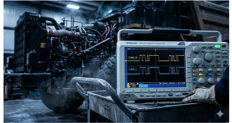
I had my Tektronix MDO34 on the cart and a growing conviction that the real fault wasn’t about lost messages. The scope uncovered something the diagnostic software had no vocabulary for: a common mode voltage shift riding the J1939 backbone.
Whether you’re maintaining a surface-mining haul truck, a harbour tug’s propulsion CAN, or an agricultural sprayer with a 60-foot backbone run, you already know the feeling: you’ve verified the power, swapped the terminators, and the bus is still cutting out the moment a high-current load kicks in. What follows is the exact procedure I used, written while the scope captures were still on the screen. Nothing hand-wavy. If you’ve got two probes, a clean ground reference, and a J1939 backbone you don’t fully trust, you can do this.
When You Should Suspect a Common Mode Problem
The giveaway on that frozen Alberta morning was subtle. The J1939 data link showed bursts of error frames on a scope, but only when the grid heaters cycled on. When the heaters were off, the bus looked textbook. What caught my attention was a slow drift — a vertical displacement — of the entire CAN waveform when referenced to battery negative.
Symptom patterns worth filing away:
- Intermittent communication loss that correlates with a specific load change (grid heater, hydraulic pump engagement, alternator ramp-up).
- Multiple ECUs logging timeout faults for different source addresses, but with no single ECU consistently dropping off.
- CAN_H and CAN_L individually appearing to have the correct peak-to-peak amplitude, yet differential decoding shows stuffed-bit errors.
- The bus works perfectly on a bench test with a service tool but fails the moment the engine block heater or a chassis load is powered.
If two or more of those sound familiar, do not reach for a replacement ECU. Reach for your oscilloscope.
What Common Mode Voltage on J1939 Actually Means
Let’s talk about what’s happening inside the silicon. Every CAN transceiver has a built-in resistive divider that biases both CAN_H and CAN_L to roughly half the 5‑volt rail when the bus is sitting idle. On a healthy J1939 backbone, a multimeter from either signal wire to battery negative reads about 2.5 volts—not because the protocol specification mandates it, but because that’s where the DC bias naturally settles when the termination resistors and the transceiver’s internal circuitry are doing their job correctly.
On that Alberta truck, the numbers were 2.53 V on CAN_H and 2.48 V on CAN_L with the key on and the grid heaters cold. Unremarkable. Exactly what every ISO 11898‑2 reference schematic would predict.
A common mode shift isn’t a change in the differential message. CAN_H minus CAN_L still looks clean on a math trace. What shifts is the entire voltage window that the receiving node uses to decide whether it’s looking at a recessive or a dominant bit. When the grid heaters pulled current through that corroded strap, the engine block rose 1.3 V relative to the cab controller’s ground. The CAN transceiver inside the display now saw CAN_H recessive at 3.8 V instead of 2.5 V. Still below the absolute‑maximum 7‑volt rating buried in the datasheet, but the receiver’s decision threshold doesn’t wait for catastrophic failure. Long before the silicon gets damaged, the bit‑sampling window turns to garbage. We were losing frames not because the messages vanished, but because the receiver’s differential amplifier was running well outside its sweet spot. This is exactly the kind of ground offset that can silently cripple a data link while every scan tool says the bus is healthy.
Over the years, I’ve watched common mode shifts originate from four or five recurring physical faults, and they’re rarely what the fault‑code screen suggests.
The most common—and the one I found in Alberta—is a ground strap that passes a continuity test but develops a significant voltage drop under load. When the engine’s grid heaters or a hydraulic powerpack kick in, the potential difference between the engine ECU’s ground and the cab controller’s ground can easily exceed a volt. That difference lifts both CAN_H and CAN_L relative to the cab‑side electronics.
Another scenario I ran into on a marine application: a CAN shield grounded at both ends of a 40‑foot harness run. That created a secondary ground path and injected a couple hundred millivolts of 60‑Hz ripple from the genset onto the signal pair. The offset was small but periodic—enough to trigger a bus‑off every thirty seconds like clockwork.
I’ve also tracked a shift to a faulty split‑termination network where the centre‑tap capacitor had leaked electrolyte onto the PCB. The recessive voltage drifted from 2.5 V to about 3.1 V over the first twenty minutes of operation as the board warmed up. That fault looked thermal on the scope and it looked thermal on the thermal camera.
And yes, I have seen a CAN transceiver with an output stage partially shorted to the 5‑volt rail inside the chip. It still transmitted valid frames, but the recessive level sat permanently at 4.1 V. Every other node on the bus had to fight uphill against that bias. We once documented a case where a faulty transceiver kept communicating for weeks before anyone noticed the elevated common mode.
The Step-by-Step Oscilloscope Measurement
I’ll walk through the exact method I used on that truck. You can replicate this with any two-channel or four-channel scope that has at least 100 MHz bandwidth. Higher sample rates help, but I’ve done this successfully with a 50 MHz Picoscope and a laptop.
What You Need
- Two-channel oscilloscope (4-channel makes the ground reference check easier)
- Two 10x passive probes (or differential probes if you prefer, but I’ll explain later why standard probes work better for this particular CAN bus diagnostic)
- BNC T-connector or a break-out box that gives you access to CAN_H, CAN_L, and ground
- A known-good 9-pin Deutsch or similar connector breakout adapter for the J1939 backbone. I carry a homebuilt tee with labeled banana jacks.
- The machine’s wiring schematic showing ground strap locations (find the physical ones, not just the logical grounds in the diagram)
Step 1: Establish Your Reference Point
Common mode voltage is meaningless without a defined reference. Do not clip your probe ground leads to any convenient bolt. Attach both probe ground leads together, and connect that single combined reference point directly to battery negative at the battery bank itself. This is the most stable, low-impedance reference available on a vehicle or machine.
On the mine truck, I used a long ground lead run from the battery box to the cab area — yes, long ground leads can pick up noise, but for DC offset measurements it’s fine. For higher-frequency noise, I’d switch to a short spring-clip ground at the ECU connector under test.
Step 2: Probe Both CAN_H and CAN_L Simultaneously
- Channel 1: probe to CAN_H at any convenient backbone access point (the diagnostic connector is ideal).
- Channel 2: probe to CAN_L at the same connector.
- Both channel inputs set to DC coupling. This is non-negotiable. AC coupling will hide the very offset you’re trying to find.
- Vertical scale: 1 V/div on both channels.
- Timebase: start at 10 µs/div to observe individual bit transitions, then zoom out to 100 ms/div to look for slow drift.
- Trigger: set to Channel 1, falling edge, threshold around 2.0 V. That gives a stable capture of dominant-state bits.
Step 3: Measure the Recessive Voltage on Each Wire
With the network idle or lightly loaded (key on, engine off if possible), note the voltage level where each waveform sits during the recessive bits — those flat segments between frames. This is your baseline common mode voltage.
In a healthy J1939 bus with proper termination, you should see approximately 2.5 V on both CAN_H and CAN_L during the recessive state. A deviation of 0.2 V either way is usually tolerable. Anything above 0.5 V deserves your full attention.
On the Alberta truck, with everything off, I measured CAN_H recessive at 2.53 V and CAN_L at 2.48 V — basically perfect. The moment the grid heaters engaged, both traces shifted upward together to 3.82 V on CAN_H and 3.77 V on CAN_L. The shift was almost perfectly in-phase. That’s the fingerprint of a common mode offset, not a wiring short or a single-ended driver fault.
Step 4: Capture the Offset Under Different Load Conditions
Now comes the most revealing part. Keep the scope running and systematically turn on high-current loads one by one while watching the common mode level. Record the offset magnitude for each condition:
| Load Condition | CAN_H Recessive (V) | CAN_L Recessive (V) | Shift from Baseline (V) |
| All off | 2.53 | 2.48 | 0.0 |
| Grid heaters on | 3.82 | 3.77 | +1.30 |
| Headlights on | 2.54 | 2.49 | +0.01 |
| HVAC blower on | HVAC blower on | 2.50 | +0.02 |
| Starter cranking | 1.10 | 1.05 | –1.43 |
The starter cranking drop was another clue — the negative offset during cranking pointed straight at a high-resistance ground path between engine block and battery negative, because the starter motor’s inrush current was creating a voltage divider across that corroded strap.
Step 5: Locate the Physical Source
Now you know the offset magnitude and the load conditions that provoke it. Use the voltmeter function on your multimeter (or a third scope channel) to measure the DC potential between the ECU ground pins of two different nodes on the bus while the offending load is active.
Pick the node that’s most communication-critical — often the engine ECU — and measure from its case ground (or connector ground pin) to battery negative. Then do the same at the next ECU upstream, like the cab controller. If you see a difference of more than a few hundred millivolts while high current is flowing, you have found your ground loop. For a complete walk-through of this diagnostic path, see our guide on how to diagnose a J1939 ground offset step by step.
On the haul truck, the voltage between the engine ECU ground pin and the cab controller ground pin was 1.31 V DC while the grid heaters were on. Cleaning and replacing the engine ground strap dropped that to 8 millivolts. The J1939 common mode returned to 2.5 V. Problem solved. Zero parts cost, aside from a ten-dollar braided strap.
Five Mistakes That Will Send You in Circles
I’ve watched capable techs burn entire shifts on this. Here’s what to avoid, along with some scars I’ve picked up along the way.
- Using AC coupling on the scope. I once spent twenty minutes on a genset controller certain the bus was clean, only to realise the scope channel had been set to AC coupling from a previous ripple test. The DC shift I was hunting was completely invisible. That’s the day I started taping a ‘CHECK COUPLING’ label to the top of every scope in the shop.
- Measuring differential voltage (Math channel) alone. A math trace of CH1 – CH2 removes the common mode component by definition. It’s useful for eye diagrams, but useless for identifying a common mode shift. I’ve seen more than one field report where a tech proudly sent a clean CH1–CH2 capture while the bus was still in error, because the common‑mode information had been stripped out. You must look at the single-ended voltages referenced to ground.
- Clipping the probe ground to a painted bracket. I watched a colleague chase a phantom 0.8 V offset for an hour because his ground clip was biting into powder coat instead of bare metal. He’d clipped onto what looked like a clean frame rail, but paint and anodizing are insulators. Always scratch through to the base metal or run a lead back to a known clean point.
- Assuming a “good ground” based on a continuity test alone. A DMM beeping at you only proves there’s a path. It doesn’t tell you if that path can handle 200 amps without turning into a resistor. I’ve seen a ground strap measure 0.2 Ω on the bench and still drop 1.5 V under cranking load. Measure voltage drop under load, not resistance.
- Blaming the ECU without testing the physical layer. I’ve lost count of how many ECUs I’ve seen pulled from a truck, only to have the same code return on the replacement because nobody put a scope on the ground. The J1939 data link is an analog signal before it’s a digital message. Skip the analog domain verification, and you’re just buying expensive hardware for no reason. That club really is crowded and expensive.
How to Confirm You’ve Actually Fixed It
A successful repair isn’t “the codes didn’t come back for ten minutes.” Here’s what a confident verification looks like:
- Re-measure the common mode voltage under all previously offending load conditions. The recessive level on both CAN_H and CAN_L should stay within 2.3–2.7 V relative to battery negative, regardless of what you switch on.
- Run a differential eye diagram (CH1 – CH2 math) and confirm the eye opening is clean with no crossing jitter. An eye pattern mask test is even better, if your scope supports it.
- Cycle the ignition and let the engine run for a minimum of thirty minutes while monitoring the J1939 error frame counter on a service tool or a data logger. A healthy bus should show zero error frames over that period.
- Perform a wiggle test on the repaired ground path and adjacent harness sections while watching for any transient common mode shifts. Some breaks are intermittent and thermal; a cold-soaked fix might still open up when the engine bay heats up.
On the Alberta truck, we logged eight hours of runtime with zero J1939 communication errors after the ground strap replacement. The mine’s reliability engineer later confirmed the same failure mode on two sister trucks. Both had the original engine ground straps, both showed common mode offsets above 1.2 V under heater load. Preventive replacement eliminated the problem fleet-wide.
Tools That Make This Easier (And What Our Shop Uses)
Over twenty years of building and troubleshooting CAN networks from industrial automation to off-highway equipment, we’ve learned which tools earn their keep. For common mode analysis specifically, a good oscilloscope with deep memory and a breakout harness you trust are worth more than any proprietary diagnostic interface.
We regularly supply engineering teams with custom J1939 diagnostic adapters, breakout cables, and test harnesses built to spec. Every unit we ship goes through a four-step quality inspection — raw cable verification, pinout continuity, a full J1939 bus simulation test under load, and a final visual check — all inside a climate-controlled production area under 5S management. The facility carries ISO 9001, ISO 14001, and IATF 16949 certifications, and all cable assemblies are RoHS, CE, and REACH compliant. UL-listed materials are standard on any harness that requires it.
If you’re troubleshooting J1939 networks regularly and need a reliable breakout that won’t introduce its own ground offsets, or if you need fully custom cables with specific AWG, length, connector orientation, and branding, we’ve been doing exactly that for two decades. No off-the-shelf compromises.
We don’t list pricing online — every order is engineered to the application. If you have a datasheet, a sketch on a napkin, or just a painful recurring field issue you’re tired of chasing, send it over. You’ll get direct engineering support, not a sales script.
Frequently Asked Questions
What is the normal common mode voltage on J1939?
With the bus in recessive state and both termination resistors in place, expect approximately 2.5 V on both CAN_H and CAN_L when measured to battery negative. A range of 2.3–2.7 V is generally acceptable. Anything outside that window under load indicates a physical-layer problem worth investigating. When I run a J1939 power‑up test on a freshly built harness in our climate‑controlled test bay, I see between 2.45 V and 2.55 V on every node. In the field, with engine running and alternator charging, anything from 2.3 V to 2.7 V hasn’t yet caused me a problem. Once I cross 0.5 V of shift under load, I stop diagnosing logic and start diagnosing ground paths.
Can I measure common mode voltage with a single probe?
You can, but it’s inefficient. Measuring CAN_H or CAN_L individually gives you one piece of the picture. The key insight comes from watching both wires shift together in real time. A two-channel scope is the practical minimum for any serious CAN bus physical layer test.
Will a differential probe eliminate the need for a ground reference?
No. A differential probe measures voltage between its two inputs regardless of ground, which is fantastic for floating measurements. But a common mode shift referenced to the ECU’s local ground is exactly what causes receiver errors. Measuring differential voltage across CAN_H and CAN_L with a diff probe will not reveal an offset relative to the ECU ground. For this specific test, single-ended measurements with careful grounding are more diagnostic. I’ve had colleagues argue otherwise, but then they can’t explain why their bus‑off disappears when they finally clip a ground lead to battery negative.
Is a 120 Ω termination resistor related to common mode offset?
Indirectly. The termination resistors provide the DC bias path that holds the recessive voltage at approximately 2.5 V (in a split-termination scheme with capacitors to ground, common in newer designs). If one termination resistor is missing or if the split capacitors are damaged, the recessive voltage can drift. A missing termination at one end often shows up as a smaller, consistent offset rather than a load-dependent one. We’ve covered termination resistance drift in detail, including how temperature changes can mimic a common mode problem.
Do I need a special J1939 breakout cable?
You don’t strictly need one, but a proper breakout cable with clearly labeled access points for CAN_H, CAN_L, shield, and ground reduces the chance of probing the wrong pin and damaging something. We make these custom for clients daily — with silkscreened labels, the specific 9-pin connector you use, and integrated test points.
How often is common mode shift the root cause in intermittent J1939 issues?
In our field experience, roughly one in five intermittent bus-off or timeout-related J1939 cases that stump the first round of diagnostics come down to a physical-layer problem like a common mode shift or ground loop. The number goes up significantly on older equipment with original ground straps and in cold climates where corrosion accelerates. For a sense of what this costs at fleet scale, take a look at our ground offset fleet cost breakdown.
Can a common mode shift damage a CAN transceiver?
Datasheets for the TJA1040 and similar transceivers quote –2 V to +7 V as the common‑mode input range, but I’ve watched an MCP2551 struggle with bit errors at 3.8 V common mode long before any permanent damage. The damage threshold is real; the signal‑integrity threshold is tighter and matters more day‑to‑day. Prolonged operation at elevated common mode voltages degrades the receiver’s noise margin and causes bit errors silently. In extreme cases — like a harness short to a 12 V supply — transceiver destruction is guaranteed.
What if my scope doesn’t have deep memory?
For slow drift measurements, memory depth is less critical than for decoding long message streams. A lower sample rate with a long time/div setting (50–100 ms/div) can capture load-step changes effectively, even with older DSOs.
Should I also look at the CAN shield voltage?
Absolutely. If the J1939 backbone uses a shield that is grounded at only one point (the standard recommendation), measure the voltage between the CAN shield and battery negative at the ungrounded end while loads cycle. Any significant voltage here suggests capacitive coupling of noise into the shield, which can capacitively couple onto the signal pair.
How do I get custom J1939 test cables for our fleet?
Reach out with your connector type, desired cable length, and any specific labeling needs. We’ll quote based on your exact requirements. No catalog, no one-size-fits-all.
A Few Final Thoughts From the Shop Floor
After that Alberta morning, I stopped thinking of the J1939 backbone as a digital network and started treating it as an analog circuit that happens to carry digital messages. The scope shows you the analogue truth. The scan tool only shows you what the ECUs managed to decode from a signal that was already compromised.
The hardest part is remembering to look for the physical layer first. Most J1939 training barely mentions common mode behaviour, and many diagnostic procedures jump straight to message-level analysis. That’s a mistake.
The next time you face an inexplicable bus‑off cascade, ask yourself: what’s changed in the physical environment when the fault occurs? A load turning on, a temperature shift, a flex in the chassis? That question, combined with two properly grounded scope probes, will find faults that parts‑swapping never will.
If you’ve got a stubborn J1939 ghost and you’re located halfway around the world, I can’t loan you my scope, but I can make sure your diagnostic harness isn’t adding to the problem. We build test cables the way we’d build them for our own bench — which is to say, with zero tolerance for ambiguity.
Have a question about a specific measurement, a vehicle you’re pulling your hair out over, or a cable design you need? Use the Contact page on our site or message directly on WhatsApp. You’ll talk to someone who understands ground loops from hard-earned experience, not from a script. We take custom OEM work seriously and provide engineering-level support from initial sketch to final assembly.
https://obd-cable.com/contact/
https://api.whatsapp.com/send/?phone=8617307168662&text=Need+Help%3F+Chat+linda+WhatsAPP&type=phone_number&app_absent=0
