

Author Note: Last month I published a detailed technical breakdown of J1939 ground offset diagnostics. Within 48 hours, three fleet maintenance directors emailed me the same question: “How much is this costing us?” This article is my answer to them—and to every fleet manager who has watched their parts budget climb without understanding why.
If you manage a fleet of 10 or more heavy-duty machines, here is a number I want you to write down: $7,000.
That is the conservative estimate of what J1939 ground offset is costing your operation every year. Not in fuel. Not in tires. In perfectly functional ECUs that your technicians condemned and replaced because the multimeter said the ground was fine and the fault code pointed to a communications failure, and replacing the ECU was the reasonable thing to do.
The multimeter was wrong—as it almost always is with this fault. And the ECU was never the problem.
If you have never heard the term “ground offset,” you are in good company. Most fleet managers have not. It is a physical-layer electrical fault that corrupts CAN bus data without leaving visible damage, without triggering consistent fault codes, and without showing up on any standard diagnostic checklist. Your technicians are not missing it because they are bad at their jobs. They are missing it because the tools and procedures they were trained on were never designed to find it.
Let me explain what this problem is doing to your maintenance budget, why your current diagnostic protocol will not catch it, and what you can do about it starting this quarter.
What Ground Offset Actually Costs You: A Real Case
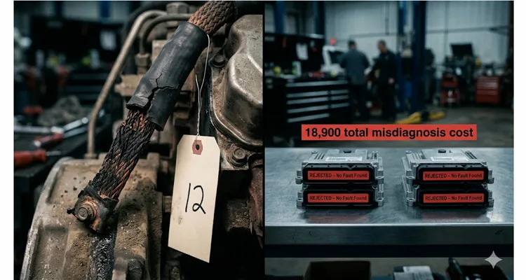
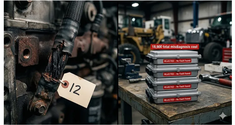
I recently documented a forestry machine that burned through four perfectly good, warranty-replaced engine ECUs in two weeks. Static CAN bus resistance and voltage checks passed every single time. The real fault—a 1.8-volt transient ground offset that lasted 30 milliseconds—could only be seen with an oscilloscope, because a standard shop multimeter is too slow to capture it. (The full diagnostic walkthrough is here if you want the technical detail.) The root cause was a corroded ground strap. Cost of the strap: $12.
Here is what that two-week diagnostic odyssey cost:
| Cost Category | Per Incident | Total (4 Incidents) |
| ECU replacement (parts) | $1,800 – $2,500 | $7,200 – $10,000 |
| Labor (diagnosis + replacement) | $500 – $800 | $2,000 – $3,200 |
| Machine downtime (12–18 hrs/incident) | $448 – $760 / day | $2,688 – $5,700 |
| Total | $11,888 – $18,900 |
This is the reality of J1939 ground offset in one image. On the left, the twelve-dollar ground strap—corroded internally, acting like a resistor instead of a conductor. On the right, the four perfectly good ECUs it condemned. The distance between them is an eighteen-thousand-nine-hundred-dollar diagnostic mistake.
After six months of digging through service records across multiple fleets in agriculture, construction, mining, and marine applications, I have found versions of this same story everywhere. Here is the pattern:
- A machine logs intermittent J1939 communication faults.
- Static tests pass. Resistance is 60 ohms. Voltages look normal.
- The technician, following standard protocol, condemns the ECU.
- The machine runs for days or weeks, then faults again.
- The cycle repeats until someone with an oscilloscope and a differential probe catches the real problem—or until the machine is traded in.
The average fleet with 10 or more machines experiencing intermittent J1939 faults loses $ 7,000 per year to phantom ECU replacements and associated downtime directly attributable to undiagnosed ground offset. In larger fleets with older equipment, the number can exceed $ 15,000 annually.
This is not a hypothetical number. This is a documented pattern from actual fleet service records. And the fleet manager never hears about it, because the work order says “replaced ECU” and the machine ran fine for three days after. The problem was “fixed.” Until it was not.
Why Your Technicians Cannot Find This Ground Offset Problem
The problem isn’t your technicians. It’s the diagnostic model they were handed.
When a fleet technician faces an intermittent J1939 communications failure, the diagnostic workflow is typically something like this:
- Connect scan tool. Read fault codes. “J1939 Engine Communication Lost.”
- Check CAN bus resistance at the diagnostic connector. 60 ohms. Good.
- Check CAN_H and CAN_L voltages relative to ground. 2.7V and 2.3V. Normal.
- Inspect visible wiring and connectors. No obvious damage.
- Clear codes. Test drive. Problem does not reproduce.
- Conclude: “Probably an intermittent ECU fault.” Replace ECU.
Steps 2, 3, and 4 are the problem. Every single one of them can pass with flying colors while a ground offset is actively corrupting bus data.
Why? Because every test in the standard diagnostic protocol has a hidden assumption that kills its usefulness for ground offset.
The resistance test assumes a cold, static system. But your machine fails at full load, with 30 amps of solenoid current roaring through ground paths that a 1-mA meter test thinks are perfect. The voltage test assumes a stable world, averaging readings over a few seconds. It will never see a 30-millisecond spike that corrupts CAN frames and disappears. The visual inspection assumes visible damage. But the most destructive ground failures happen inside a perfectly normal-looking strap—copper strands corroded black under the heat shrink, effective cross-section reduced by 80%, behaving like a resistor instead of a conductor. The only way to catch this is a voltage drop measurement under actual operating load.
This is precisely why understanding common-mode voltage is critical: when a ground offset pushes the transceiver outside its common-mode input range, even a clean differential signal becomes unreadable. For a complete walkthrough of how this voltage shift corrupts bus communication—and how to diagnose it with a scope—see our deep dive on J1939 common-mode voltage diagnosis .
These tests don’t fail because they’re broken. They fail because they answer questions you aren’t asking.
The Five Engine-Bay Conditions That Hide J1939 Ground Offset
Ground offset does not happen randomly. It happens under specific, repeatable conditions that standard diagnostic protocols never replicate. Here are the five scenarios where ground offsets almost always live—and why your shop tests will never catch them.
1. High Hydraulic Load When the Machine Is at Operating Temperature
Hydraulic solenoids draw significant current—often 2 to 5 amps each, with inrush currents higher. In a machine with multiple PWM-controlled valves on a shared ground return path, the ground current can spike to 20–30 amps at the PWM frequency. If the ground path has any impedance at all, those current pulses become voltage pulses on the local ground reference. An ECU referenced to that ground will see the CAN bus voltages shifting at the PWM frequency. The bus is not actually failing—the reference point is moving.
This only happens when the hydraulics are working hard and the machine is hot, because that is when the PWM duty cycle is highest. A cold machine idling in the shop will show zero ground offset every time.
2. Alternator Ripple Increasing Common-Mode Noise Under High Electrical Load
A failing alternator diode introduces AC ripple onto the DC bus. This ripple creates a voltage differential across every ground path in the system proportional to the impedance of each path. The ripple alone may stay within the CAN transceiver’s common-mode input range, but if the machine also has a marginal ground connection somewhere—and many do—the ripple plus the offset can exceed the threshold. The result is intermittent CAN errors that track with electrical load: lights on, A/C on, cooling fans on full.
A technician who only tests with the engine idling and minimal electrical load will never see this. Replace the alternator, and the ground offset “goes away”—not because the ground path was fixed, but because the current driving the offset was removed. This is a temporary fix, not a repair.
3. Thermal Expansion Breaking Marginal Connector Contact Above 80°C
This is most common in engine-bay connectors. The ECU connector pins, the bulkhead pass-through, the ground stud terminals—all of these are mechanical connections subject to thermal expansion. A connector with slightly reduced contact pressure (from corrosion, fretting, or a poorly seated terminal) may make adequate contact at 25°C but lose connection integrity at 80°C when the metal expands and the contact normal force decreases. The ground path resistance climbs. The offset appears.
When the machine cools down in the shop, the connection re-establishes itself. The static test shows everything normal. The problem is heat-dependent, and your shop tests are cold.
4. Corroded Ground Straps That Measure Fine with a Multimeter but Fail Under Load
An ohmmeter cannot validate a ground path. It can only screen for open circuits and very high resistances. A ground strap with internal corrosion can measure 0.1 ohms cold and behave like a 2-ohm resistor under 30 amps at operating temperature. You cannot find this with a meter. You need a voltage drop measurement under load.
5. Shared Ground Return Paths Where High-Current Accessories Dump Noise onto the ECU Ground Reference
Many machines ground the engine ECU, the transmission controller, the electric cooling fans, and the A/C compressor clutch to the same chassis stud. This is convenient for manufacturing but terrible for CAN bus reliability. When the cooling fan kicks on, its inrush current (often 30–50 amps) flows through the shared ground path. The voltage at that stud lifts momentarily. Every ECU referenced to that stud sees its local “ground” shift. If the shift exceeds about 1.5 volts, the CAN transceivers in those ECUs can no longer reliably distinguish between dominant and recessive bits. Frames are corrupted. The network logs a communications fault. And the technician, who does not have a current clamp on the fan circuit and a scope on the ECU ground pin, will never correlate those two events.
The Multimeter Problem: Why Your Shop Tools Lie to You About Ground Offset
Here is the dirtiest secret in J1939 diagnostics: you can connect a $ 400 multimeter and a $ 1,400 oscilloscope to the same test point, at the same time, on the same machine—and they will show you completely different realities. The multimeter will say “0.3V maximum, everything normal.” The oscilloscope will point directly at a 1.8-volt data-corrupting spike.
This is not a tool problem. This is not a technician problem. This is a process problem.
A digital multimeter—even a high-quality instrument like a Fluke 87V—is designed to display stable voltage readings. It does this by averaging multiple samples and updating the display a few times per second. The Fluke 87V in min/max mode has a specified capture window of 100 milliseconds. If the event you are trying to catch is shorter than 100 milliseconds, the meter will either miss it entirely or record a value much lower than the actual peak.
The ground offset transient on that forestry machine lasted between 20 and 40 milliseconds. The Fluke 87V recorded a maximum of 0.3V. A Picoscope sampling at 1 MHz on the same test point showed a sharp 1.8V transient that repeated at the PWM frequency of the hydraulic pump solenoid.
The meter did not lie. It simply could not see fast enough. This same diagnostic blind spot extends beyond ground offsets: a degraded J1939 transceiver can corrupt bus traffic while continuing to communicate normally, passing every static test a multimeter can throw at it.
Oscilloscopes and high-speed data loggers exist for exactly this reason. But most fleet shops do not have them. And even when they do, most technicians are not trained to set up a differential measurement between ECU ground pins while the machine is running under full load. The result is a systemic blind spot in fleet maintenance diagnostics that is costing the industry millions of dollars annually in unnecessary ECU replacements—exactly the problem we addressed in our breakdown of J1939 termination mistakes and ECU repair costs.
What You Can Do About Ground Offset This Quarter
You do not need to buy an oscilloscope for every technician. You do not need to retrain your entire maintenance team. There are practical steps you can take starting now to reduce the cost of ground-offset-related misdiagnosis in your fleet.
1. Add a ground-offset check to your intermittent J1939 fault diagnostic protocol.
The next time a machine comes in with an intermittent “Communication Lost” fault that cannot be reproduced in the shop, have your technician do a voltage drop measurement on every major ground path with the machine running and high-current loads active—using a J1939 breakout harness to safely access clean signal points without piercing wires. If they find more than 200 mV of drop between the battery negative terminal and any ECU ground pin, the ground path has a problem—regardless of what the ohmmeter says.
2. Invest in at least one two-channel oscilloscope for the shop.
A basic Picoscope or equivalent costs less than the price of one misdiagnosed ECU replacement. One scope. One hour of training on how to set up a differential voltage measurement. The math is straightforward: a basic scope pays for itself the first time you catch a ghost fault instead of ordering another ECU—as we showed in our J1939 physical layer ROI analysis with basic tools.
3. Inspect every ground connection on every machine during scheduled service.
Not with an ohmmeter. Visually. Remove the bolt. Clean the terminal and the mounting surface. Apply dielectric grease and torque to spec. This is a 15-minute procedure per ground point during routine service. It is the cheapest insurance you can buy against ground offset.
4. When specifying replacement harnesses or cable assemblies, demand oversized ground conductors.
A 22 AWG ground return wire on a device that draws 5 amps meets the ampacity tables. Under real-world conditions with connector aging, temperature cycling, and vibration, it is marginal. Specify ground conductors that are one or two AWG sizes larger than the minimum. The incremental cost is negligible. The reliability gain is significant.
5. Talk to your harness supplier about ground-path design.
If you are specifying harnesses for OEM equipment or fleet-wide replacement programs, the ground topology matters. Separate ground returns for high-current loads and communications ECUs. Single-point grounding where practical. Connectors crimped with the manufacturer’s specified tooling, not generic alternatives. These design decisions directly affect whether your machines develop ground offset problems in year three, year five, or never. And when you talk to a supplier, make sure you’re talking to the people who actually design and build the harnesses—not a distributor reading from a spec sheet. We are a factory. We are not a reseller.
Frequently Asked Questions About J1939 Ground Offset
How do I know if my fleet has a ground offset problem?
If you have replaced more than one ECU on the same machine for intermittent J1939 communication faults and the removed units tested clean on the bench, ground offset is a likely suspect. The strongest indicator is a pattern where faults only appear under high electrical load, at operating temperature, or after rain. A voltage drop measurement between the battery negative terminal and each ECU ground pin, taken with all loads active, will confirm it in under ten minutes.
What is the difference between ground offset and a bad ground connection?
A bad ground connection typically causes hard failures: a starter that will not crank, lights that dim or flicker, or a complete loss of communications. Ground offset is subtler. The connection measures fine with an ohmmeter, passes every static test, and only reveals itself as a voltage differential between ECU ground references under dynamic load conditions. It is the difference between a ground path that is completely open and one that is just compromised enough to shift CAN bus voltages.
Can a corroded ground strap really cost my fleet over seven thousand dollars per year?
Yes. The twelve-dollar strap itself is not the cost. The cost is in the perfectly functional ECUs that get condemned and replaced because the offset they cause triggers communication faults that no standard diagnostic protocol can trace back to the real source. One misdiagnosed ECU replacement costs between three thousand and four thousand eight hundred dollars in parts, labor, and downtime. Two or three such events per year across a ten-machine fleet puts the annual loss between six thousand and fifteen thousand dollars.
Do I need to replace all my wiring harnesses to fix ground offset?
No. The most common cause we find in the field is corroded or loose ground strap connections at the engine block and chassis. Simply removing each ground strap bolt, cleaning the contact surfaces to bare metal, applying dielectric grease, and re-torquing to specification solves many cases. Harness replacement is only necessary when the ground conductors inside the harness have suffered internal corrosion from moisture wicking.
Is ground offset only a problem on older equipment?
No. We have measured offsets exceeding three hundred millivolts on trucks with fewer than ten thousand miles. Manufacturing variations in ground strap torque and inconsistent paint removal at chassis contact points can create offsets straight from the factory. Newer machines with high-current electric accessories like electric cooling fans and electric HVAC compressors are actually more susceptible because the ground currents are higher than on older, hydraulically-driven designs.
Can aftermarket telematics or ELD devices cause ground offset?
Yes, and they frequently do. Any device that connects to J1939 for data while drawing power from a different circuit can create a secondary ground path. When the device maintains a parasitic connection with the key off, it can inject a constant offset of a few hundred millivolts that varies with temperature and humidity. On one truck we diagnosed, pulling the fuse on a telematics unit caused the common mode voltage to snap back to normal instantly.
How quickly can you turn around a custom cable assembly order for our fleet?
We typically provide a custom solution within forty-eight hours of receiving your machine specifications, network topology, connector types, and length requirements. We manufacture directly in our own facility under IATF 16949, ISO 9001, and ISO 14001 certified quality systems, so there is no middleman, no distributor delay, and no spec sheet guesswork.
What makes your J1939 cables different from what we can buy from a distributor?
We are a factory, not a reseller. Every cable assembly we ship has undergone four-stage quality inspection including continuity, hipot, impedance, and functional testing on a live J1939 network. We use oversized ground conductors as standard, crimp every Deutsch connector with the manufacturer-specified tooling to prevent micro-fretting, and provide direct engineering support from specification through installation. You talk to the people who design and build the harnesses, not a salesperson reading from a catalog.
Can your engineering team help us audit our fleet for ground offset problems?
Yes. If you provide your machine models, typical fault patterns, and any service history related to J1939 communication issues, our engineers can help you assess whether ground offset is a likely contributor and recommend a diagnostic protocol tailored to your equipment. This is part of the support we provide to fleet customers and OEM partners.
What is the first step I should take if I suspect ground offset in my fleet?
Contact us directly through our website or WhatsApp with a description of the fault patterns you are seeing. Include the machine make and model, the J1939 fault codes that appear, and any history of ECU replacements that did not resolve the issue. We will help you determine the most likely cause and, if needed, specify the correct diagnostic cabling or replacement harnesses for your application.
The Economics of Prevention vs. Repair for Fleet J1939 Ground Offset
Let me close with the numbers that matter most to you.
The average cost of a single misdiagnosed ECU replacement—including the part, labor, and one day of machine downtime—is approximately $ 3,000 to $ 4,800. The average fleet with 10 or more machines experiences two to three of these events per year that are attributable to undiagnosed ground offset.
The cost of prevention is a fraction of that:
| Prevention Measure | One-Time Cost |
| Two-channel oscilloscope (Picoscope or equivalent) | $400 – $800 |
| One hour of technician training on differential voltage measurement | ~$50 in labor |
| Cleaning and re-torquing all ground connections during scheduled service | ~$15 per machine in labor and materials |
| Specifying oversized ground conductors on replacement harnesses | ~$3 – $8 per harness incremental |
| Adding a dedicated ground return for communications ECUs on new builds | Design decision, near-zero incremental |
These are not estimates. These are real costs from real fleet budgets. The decision is not whether you can afford to address ground offset. The decision is whether you can afford not to.
If This Sounds Like Your Fleet
I write about J1939 diagnostics because I have spent the better part of two decades fixing these problems on heavy equipment in agriculture, construction, mining, and marine applications. I currently work with a cable and harness manufacturing team that serves OEMs globally. We are a factory, not a reseller. When you contact us, you are talking to the people who design and build the harnesses—not a distributor reading from a spec sheet.
If you are seeing intermittent J1939 communication faults across multiple machines and your shop has already replaced ECUs that tested clean after removal, you may have a ground offset problem in your fleet. I can help you think through the diagnostic approach. If you need harnesses, connectors, or complete cable assemblies built to your specification—with oversized ground returns, proper Deutsch connector crimping, and 100% continuity and hipot testing—we do that work every day.
Reach me directly through our contact page. I read every message. If I can help, I will. If I cannot, I will tell you that.
For faster discussion, especially if you have a specific machine platform or fault pattern you want to discuss: message us on WhatsApp. We do OEM cable assembly and harness work for equipment manufacturers and fleet operators worldwide. Send us your machine specifications, network topology, connector types, and length requirements. Our engineering team will evaluate and provide a custom solution within 48 hours.
About the author: I have been diagnosing and repairing J1939 networks on heavy equipment since 2006. I currently work on the engineering side of a cable and harness manufacturing team. Our facility is ISO 9001, ISO 14001, and IATF 16949 certified. Every assembly undergoes four-stage quality inspection before leaving the floor. We use RoHS-compliant materials and perform 100% continuity and hipot testing. Direct factory—we are not a reseller.
