

Let me paint a scene that cost one regional hauler $12,000 in lost billings on a single Thursday.
The vehicle was a 2022 Class 8 sleeper cab — 580 horsepower, automated manual gearbox, every safety initialism the window decal could accommodate. The operator was 400 miles deep into a 650-mile temperature‑controlled haul when the instrument cluster erupted. ABS caution. Transmission malfunction. Engine derate. He nursed the rig into a travel plaza and burned six hours waiting for a mobile technician.
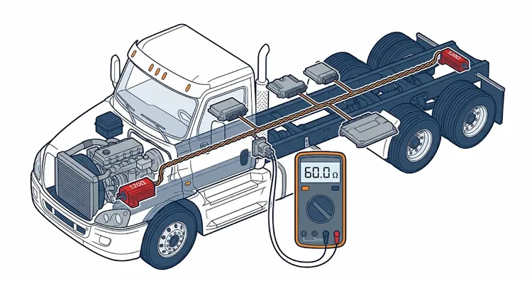
The field tech uncovered precisely what anyone would anticipate: J1939 communication errors. SPN 639 FMI 9 — the all‑purpose “something’s wrong on the CAN bus” flag. He ran the customary diagnostic ritual. Measured resistance between pins C and D on the 9‑pin Deutsch connector. Sixty ohms precisely. Voltage? 2.6V on CAN H, 2.4V on CAN L — exactly what the training manual promises. Every ECU acknowledged its polling request. He purged the fault memory, turned the key, and the engine settled into a steady idle. He scribbled his initials and sent the truck back onto the interstate.
Forty‑seven miles later, that identical rig was motionless on the shoulder again.
Nearly every J1939 troubleshooting article terminates at this exact junction. They chant “60 ohms good, 120 ohms bad” and then go silent. If you’ve turned wrenches long enough, the rhythm is depressingly familiar. You’ve observed the textbook 60‑ohm reading at the 9‑pin diagnostic connector, closed the repair order, and then fielded the callback before the rig even cleared the scale house. The wiring harness appeared flawless under shop lighting. Yet beneath the cab floor, where exhaust manifold radiation heats the asphalt to 180 degrees, the copper resistance coefficient drifts just enough to transform what should be a stable termination into a 180‑ohm antenna.
I’m after a more substantive examination. I want to dissect what actually fractures — not the laboratory‑conditions edition of J1939, but the version that survives underneath the floorboards of a truck that’s moved crushed stone across seven Midwestern winter seasons. The objective is a mental framework for this network that transcends memorized values, moving you from perpetual reaction to deliberate prevention. For a methodical approach to tracking down these exact failure signatures, we’ve documented the precise 20‑minute J1939 data link diagnostic checklist our engineering staff relies on.
Why Your J1939 Network Operates Flawlessly on the Bench and Crumbles in Revenue Service
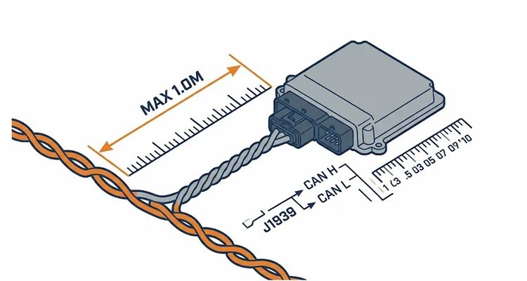
Here’s a realization that required multiple seasons to internalize completely: the SAE J1939 standard physical layer constraints are articulated for idealized, motionless conditions. Forty meters of backbone maximum. One meter of stub per ECU maximum. Thirty nodes maximum. 120‑ohm termination fastened at both absolute extremities of the network.
Forty meters appears generous when viewed on a computer‑aided design screen. That distance vanishes once you route around a DEF tank and a PTO shaft. The numeric boundaries aren’t pulled from thin air. They descend directly from signal propagation physics at 250 kbps over a differential bus whose characteristic impedance resides near 120 ohms. When you terminate a 120‑ohm cable with a 120‑ohm resistor, you suppress signal reflections.
But steel and copper expand at different rates when underhood ambient temperatures lurch between -20°F and 180°F. That mismatch is the gulf separating desktop engineering from actual fleet operation.
I was summoned to a concrete mixer fleet roughly four years ago where the OEM installation tracked the printed guidelines meticulously. Backbone topology. Stubs maintained under one meter. Two distinct 120‑ohm terminating resistors. In spite of this compliance, three mixers out of fourteen experienced sporadic communication interruptions with the transmission controller — exclusively under peak torque demand, exclusively when the powertrain was thoroughly heat‑soaked.
Two weeks of chasing intermittent symptoms finally identified the mechanism. One of the “external” terminating resistors had been secured to a bracket that twisted fractionally during high‑torque engine roll. Across thousands of miles, that minute displacement produced micro‑fractures in the solder joint sealed inside the connector cap. When cold, the joint remained electrically continuous. Heat‑soaked, with the engine rocking against its isolators, resistance climbed to 180 ohms, then 220 ohms, then open circuit. The network collapsed, the transmission reverted to limp mode, and by the time the mixer coasted back into the service bay, every meter value had returned to nominal.
The J1939 specification instructs what to install. It makes no prediction about how that resistor’s mounting bracket will endure 200,000 miles of vibration, or how moisture will migrate upward along a stub harness that someone secured to a frame rail at precisely the wrong drainage angle. Those nuanced details determine whether your fleet remains revenue‑active or parked. We’ve observed operations waste thousands in unwarranted ECU swaps hunting exactly these categories of J1939 phantom faults that were purely physical‑layer in origin.
Backbone, Stub, Termination: Re‑examining the Fundamentals
The Backbone Is Not Merely a Conductor — It’s the Central Nervous Pathway of Your Heavy‑Duty Vehicle
In a properly architected J1939 network deployment, the backbone constitutes a single, uninterrupted linear bus traversing the vehicle’s longitudinal axis, with each ECU attached through a brief spur identified as a stub. This is not a star topology. It is not an arborescent branching structure. It’s a continuous trunk with abbreviated appendages, and the physical routing arrangement exerts far greater influence than numerous installers recognize.
Consider the arithmetic that rarely gets computed but is always felt: At 250kbps, a single bit occupies a 4‑microsecond interval. Electricity travels approximately 4.5 meters through copper during that window. At 40 meters, the signal edge departing the engine ECU is merely arriving at the trailer ABS module while the engine ECU has already progressed to the succeeding bit. You’re no longer grappling with data collisions; you’re contending with temporal smear. This clarifies why 41 meters may perform acceptably for months — right up until a telematics gateway retrofit compresses the inter‑frame space sufficiently to push the network past its stability threshold.
Before we examine what happens when the backbone is compromised, it helps to visualize the ideal configuration. The diagram below illustrates a proper J1939 backbone topology: a single unbroken trunk line, stubs kept under one meter, and precisely two 120‑ohm terminating resistors anchored at the farthest physical ends of the network. Notice the 60‑ohm reading at the 9‑pin Deutsch diagnostic connector — the signature of a correctly terminated bus.
The official documentation downplays the necessity of an unbroken backbone. I’ve witnessed harness builders introduce splices mid‑backbone because it appeared “more expedient than drawing fresh continuous conductor.” Every splice generates an impedance discontinuity — a modest electrical perturbation that returns a fraction of signal energy toward its origin. A lone splice may escape detection. Two or three, and signal integrity deteriorates in ways that materialize only when bus load surpasses 60% or 70%.
Stub Length: The 1‑Meter Rule Is Not a Suggestion
The J1939/11 documentation restricts stub length to one meter. This value originates from the electrical transit interval of a stub relative to the rise time of a CAN signal. The CAN bus physical layer requirements are comprehensively detailed by semiconductor manufacturers. At the junction where a stub branches, the signal partitions. A portion of the energy continues along the backbone. A portion travels down the stub, meets the ECU input impedance, and reflects backward. When the stub remains electrically compact, that reflection returns while the original signal is still transitioning, and the CAN transceiver processes it without error.
At one meter, you’ve consumed essentially all the tolerance. At two meters, you’re gambling with the odds. I encountered a transit bus where a stub extended beyond six meters — a technician had lengthened an aftermarket telematics device’s harness with a generic extension cord to access the dashboard enclosure. That component wasn’t merely malfunctioning; it was polluting bus traffic for every other module sharing the network. The bus operated correctly perhaps 80% of the time, which rendered diagnosis an infuriating exercise. This is precisely the variety of J1939 phantom fault that consumes technician hours without resolution.
J1939/15, which employs unshielded twisted pair, permits stub lengths up to three meters under specified constraints. Interpret that as permission for relaxed discipline at your peril. Extended stubs introduce greater reflection energy, requiring compensatory margin elsewhere — a more abbreviated total backbone, diminished node count, stricter termination placement. Every variable is interconnected.
Termination Placement: The Distinction Between “End” and “Wherever It’s Convenient”
I’ll defend this principle unequivocally.
A J1939 network requires precisely two 120‑ohm terminating resistors, positioned at the physical extremities of the backbone. Not three. Not one. And certainly not “approximately midway because that’s adjacent to the fuse panel.”
With precisely two resistors anchored at the ends, the aggregate DC resistance between CAN H and CAN L — measured with system power disconnected — equates to 60 ohms. This functions as an initial diagnostic checkpoint, to which we’ll return. However, placement governs AC behavior equally. A resistor located incorrectly modifies not only the DC resistance but also the pattern determining where signal reflections are absorbed versus where they’re permitted to reverberate. We’ve assembled the complete J1939 backbone and termination design guide that examines every facet of executing this correctly.
I’ve maintained vehicles where an ECU with internal termination — a characteristic prevalent in modern engine controllers and select transmission modules — resided mid‑backbone, and the upfitter never recognized the resistor was active. The network contained three terminators: two external caps properly situated, plus the embedded resistor inside the ECU. DC resistance depressed to 40 ohms. The bus continued operating after a fashion, yet error frames amassed silently, and every few operational hours a module would disappear and re‑arbitrate for a network address.
At this juncture the OEM documentation carries more weight than the generic standard. Certain ECUs provide configurable termination — a pin pair you jumper to engage or disable the internal resistor. Others offer no such flexibility. Particular vehicle platforms designate the ABS controller as one backbone endpoint and the engine ECU as the opposing terminus. Some conceal both terminators in weatherproof caps integrated into the harness loom.
Before attaching any supplementary device to a J1939 network, you must determine unequivocally where your termination originates. Absent that knowledge, you’re navigating by assumption.
Step‑by‑Step: Designing and Validating a J1939 Network That Endures
I’ll present a workflow. It’s the identical procedure I’ve employed to commission networks encompassing single vocational chassis through multi‑trailer road train configurations. It isn’t the exclusive methodology, but it intercepts failures before they strand a vehicle roadside. For a thorough CAN bus physical layer testing guide that elaborates on each of these stages, we’ve published the complete protocol.
Step 1: Map the backbone before you touch a single wire.
- Render a sketch. Paper, whiteboard, tablet — the medium is irrelevant. Visualize the physical routing path.
- Identify every ECU mounting position.
- Observe where the backbone travels relative to heat sources (exhaust manifolds, turbocharger housings), vibration sources (engine mounts, axle carriers), and moisture paths.
- Mark each terminating resistor location — then confirm, using a multimeter and the OEM wiring diagram, whether those resistors are contained in external caps or are internal to an ECU.
Step 2: Design your stub lengths with margin, not minimums.
- The standard permits one meter. For fresh designs, target 30 centimeters or less.
- Each centimeter conserved constructs buffer for the eventual day a new device enters the network.
- If a stub must approach one meter, verify it is not routed parallel to high‑current power cables and does not traverse regions susceptible to pinching, abrasion, or direct road spray exposure.
Step 3: Validate the backbone before connecting any ECUs.
- This validation stage is routinely omitted, yet it distinguishes dependable networks from temperamental ones.
- With the backbone positioned but before attaching any modules, measure resistance between CAN H and CAN L. Expect 60 ohms — the parallel combination of the two 120‑ohm terminators.
- A reading of 120 ohms signals a missing terminator. Any alternative value indicates an issue requiring resolution before introducing additional complexity. Interpreting these readings correctly demands familiarity with J1939 CAN High and CAN Low voltage behavior.
Step 4: Add ECUs one at a time and verify.
- Attach the first ECU — ideally one that contains a terminator, where relevant — and re‑measure resistance. It should remain near 60 ohms (within a 5% tolerance band).
- Connect the subsequent ECU, measure again. If resistance declines measurably, you’ve probably uncovered a module with internal termination you hadn’t accounted for. Address it immediately.
Step 5: Verify under load and temperature.
- This step unmasked the concrete mixer fleet’s intermittent failure.
- Exercise the network at full load — every ECU active, bus load exceeding 40% where achievable — and monitor for error frames.
- Repeat the exercise with the engine heat‑soaked. Then repeat while the vehicle is moving, if safe to coordinate.
- Faults that lurk concealed at idle frequently reveal themselves when the chassis twists and underhood temperatures approach 80°C. This is also why comprehending J1939 voltage drop in field conditions matters.
Step 6: Document what you did and why.
- The next technician to service this network will appreciate the record. That technician may be you, three years hence, attempting to recall where the rear terminator cap was hidden.
- Record the details. Capture photographs. Store the documentation somewhere more durable than the glove compartment of a truck destined for remarketing next quarter.
Five Common J1939 Mistakes That Will Haunt Your Fleet
These aren’t abstract possibilities. I’ve witnessed each scenario in the field, and each has generated authentic downtime.
The table below supplies a rapid reference correlating what you observe with what the instrumentation reports:
| Symptom (What You See) | Multimeter Reading (DC) | What the Oscilloscope Shows (AC/Transient) | Root Cause Fix |
| Random ABS dropouts on rough road surfaces | 60.0 Ω | Intermittent Recessive Voltage Drops to 1.8V | Terminator Cap Flex: Resolder or substitute with sealed, strain‑relief cap. |
| Engine won’t start after hot soak cycle | 40.0 Ω | Dominant State clamped at 1.5V (Weak Drive) | Hidden 3rd Terminator: Deactivate internal resistor on mid‑bus ECU. |
| Transmission stuck in gear | 120.0 Ω | Massive Ringing on falling edges | Missing Terminator: Install resistor at physical end of line, not nearest splice. |
| Ghost codes coinciding with A/C clutch engagement | 60.0 Ω | Common Mode Noise spikes of 4V+ | Shield Grounding Error: Remove ground loop (ground shield at ONE end exclusively). |
1. Treating all 120‑ohm resistors as interchangeable.
A purpose‑fabricated J1939 terminating resistor — furnished with a sealed Deutsch connector, gold‑plated terminals, and an integrated strain‑relief boot — differs fundamentally from a generic through‑hole resistor hand‑soldered across two pins and enveloped in electrical tape. The workbench version performs on a test table. It fails consistently on a vehicle exposed to vibration, moisture, and thermal cycling. Comprehending Deutsch connector selection and maintenance is essential for sustained dependability.
2. Assuming “60 ohms” means “healthy.”
Sixty ohms across CAN H and CAN L confirms that two 120‑ohm resistors reside somewhere on the bus. It furnishes zero intelligence about where they reside, whether they occupy the ends, or whether the wiring between them remains unbroken. I’ve diagnosed networks that measured 60 ohms at the diagnostic connector yet possessed a fully severed backbone between the second and third ECUs — the network comprised two independent segments that fortuitously shared a termination resistance magnitude.
3. Mixing J1939/11 and J1939/15 components without understanding the implications.
J1939/11 employs shielded twisted pair with the shield grounded at a solitary reference point. J1939/15 utilizes unshielded twisted pair. I examined a vehicle where the body builder inserted a 6‑foot segment of untwisted, unshielded wire to reach a rear camera mounting location. On the scope, differential voltage seemed within bounds. Yet the Sync Field was under assault from fuel injector solenoid switching transients. The CAN controller expended disproportionate resources re‑synchronizing, delaying actual data payload delivery. The J1939 spec designates this a ‘Form Error.’ Our team designated it “truck refuses to upshift past 7th gear exclusively when fuel level dips below half a tank.”
4. Ignoring stub length on the basis of “it works now.”
I cited the six‑meter stub previously. It operated — temporarily. The fleet subsequently incorporated a telematics gateway that raised bus load from 35% to 55%, and modules commenced dropping offline unpredictably. The extended stub had been progressively eroding signal integrity the entire time; the supplementary bus load merely surpassed the residual tolerance. Correlation doesn’t equate to causation, yet in CAN networks, margin erosion is measurable.
5. Mounting terminating resistors where they can move or corrode.
The resistor that afflicted the concrete mixer fleet wasn’t a defective component — it was a flawed mounting decision. Terminating resistors require secure fastening to a surface that doesn’t flex, twist, or vibrate independently of the harness. They must be oriented such that moisture drains away from the connector interface, not toward it. A Deutsch connector resists moisture when fully mated; it does not resist moisture after six months immersed in a saltwater accumulation. For J1939 Deutsch DT and HD connector guidance, we’ve recorded the proper installation techniques.
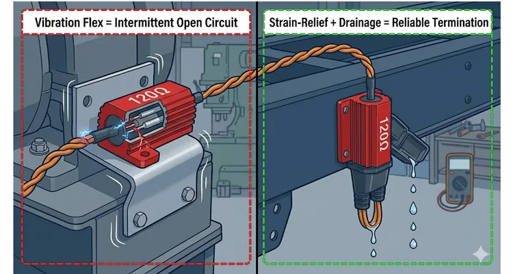
The failure mode described earlier — the concrete mixer fleet’s intermittent limp mode — is visualized below. The image on the left shows a terminating resistor rigidly mounted to a bracket that flexes with engine torque. Over thousands of miles, this micro‑movement induces solder joint fractures inside the sealed connector cap, producing an open circuit only when hot and under load. The correct installation on the right uses a strain‑relief boot and secures the resistor to a surface that does not twist independently of the harness, allowing moisture to drain away from the connection.
How to Know You Actually Remedied the J1939 Fault
The truck that stranded roadside — the case that commenced this discussion — eventually received a permanent resolution. The second diagnostic iteration utilized an oscilloscope rather than depending exclusively on a multimeter. The scope captured brief, episodic collapses in differential voltage synchronized with transmission shifts under load. Tracing the harness backward, we identified a section of backbone compressed between the cab floor structure and a crossmember — damage incurred during a prior repair operation. The insulation on CAN H had abraded sufficiently to short against the chassis when the cab twisted.
The correction involved a proper harness section replacement — not a splice, but a fresh segment terminated with sealed connectors — and revised routing that bypassed future pinch regions. That truck accumulated another 180,000 miles without a single J1939 fault.
Verification necessitates a sequence, not an isolated measurement: resistance (60 ohms, system powered down), voltage (2.5V nominal on each line, powered, bus idle), differential voltage (minimum 1.5V peak‑to‑peak during active communication), and a road test replicating genuine operational conditions. If you cannot conduct the road test personally, instrument the vehicle and capture bus traffic across a complete duty cycle. The failures that matter most materialize solely when the vehicle performs its intended work. When selecting between a multimeter and an oscilloscope, our CAN bus diagnostics multimeter vs scope guide clarifies which instrument to deploy and when.
When the Standard J1939 Harness Isn’t Sufficient
A juncture arrives where even conscientious design collides with the boundaries of catalog components. Perhaps your backbone must extend beyond 40 meters and incorporating a bridge isn’t viable. Perhaps stub lengths are dictated by ECU placement beyond your authority. Perhaps you’re integrating aftermarket equipment onto a network that never contemplated such expansion.
This intersection is where our capability becomes relevant. We function as a direct factory with over 20 years of experience manufacturing J1939 harnesses, cables, and connectors. Our operations maintain ISO 9001, ISO 14001, and IATF 16949 certifications. Every assembly we ship passes a four‑step quality inspection protocol that incorporates 100% electrical testing. Our products satisfy RoHS, CE, UL, and REACH requirements.
Importantly, we furnish OEM customization — cable length, wire gauge (AWG), connector types, color coding, branding, and even custom pinouts for specialized applications. If your project demands a backbone harness precisely adapted to your vehicle’s routing rather than a modified generic offering, we produce it. If you require stubs with specific connector orientations or sealed junctions for aggressive environments, we produce those as well. For fleets analyzing long‑term economics, our J1939 cable TCO procurement guide deconstructs the genuine ownership expense beyond initial acquisition cost.
During our 100% continuity and hipot test on a harness, we’re assessing more than simple pin‑to‑pin connectivity. We’re scanning for the subtle impedance bump that might evolve into a CRC Error on that concrete mixer 40,000 miles into its operational life. That distinction differentiates a commodity cable from an engineered interconnect. This is also why we’ve invested in enabling technicians to comprehend J1939 network calibration and fix procedures.
We don’t display pricing online because each requirement differs materially. If your priority is the absolute minimal unit cost, our alignment may be imperfect. What we provide is engineering support — a resource who will scrutinize your network design and evaluate its viability before you commit to tooling investment.
If you’re managing a J1939 network that surpasses the intricacy of conventional reference designs, or if you’re preparing a fresh integration and intend to establish the physical layer correctly from commencement, initiate contact. We’ll assist you in constructing a system that remains operational. For a more profound appreciation of what the physical layer actually costs your operation, our J1939 physical layer ROI analysis demonstrates precisely how fundamental diagnostic tools can reduce downtime by 70%.
📞 Chat with our engineering support on WhatsApp
📧 Send us your specifications via Contact Form
FAQ
Q: What’s the difference between J1939/11 and J1939/15?
A: J1939/11 utilizes shielded twisted‑pair cable intended for high‑noise environments and prevails in heavy‑duty on‑highway trucks. J1939/15 employs unshielded twisted pair and permits extended stubs (up to 3 meters) but provides reduced noise immunity. The two are not directly interchangeable without assessing the particular electrical environment. We’ve explored this comprehensively in our J1939 cable shield and impedance specification guide.
Q: Can I test a J1939 network with just a multimeter?
A: Partially. A multimeter detects gross failures — open circuits, shorts to power or ground, missing termination resistors. It cannot detect intermittent problems, signal integrity issues, or bus loading problems. For those, you need a scope or a dedicated CAN analyzer. A 30‑minute CAN bus physical layer test can conserve $800 in dealer diagnostic charges.
Q: What happens if I use the wrong AWG for the backbone?
A: The characteristic impedance of CAN bus cable depends partly on conductor geometry. J1939 installations commonly specify 18 AWG to 22 AWG twisted pair. Substituting a considerably different gauge modifies impedance and may amplify reflections.
Q: Why do I read 60 ohms at the diagnostic connector but still have communication errors?
A: A 60‑ohm reading confirms that two 120‑ohm terminators reside somewhere on the bus. It doesn’t verify they’re positioned at the correct physical ends, that the backbone wiring between them is unbroken, or that stubs remain within limits. Physical location governs AC signal behavior even when DC resistance appears nominal.
Q: Can I run J1939 alongside high‑current power cables?
A: Avoid it when feasible. High‑current cables produce magnetic fields that couple into the CAN bus, particularly during extended parallel routing. If paths must intersect, cross at 90 degrees. If parallel routing is unavoidable, maintain minimum 150mm separation and employ shielded cable (J1939/11) with the shield grounded at a solitary reference point.
Q: How do I know if an ECU has internal termination?
A: Consult the OEM documentation. Numerous modern ECUs incorporate configurable termination — sometimes engaged by shunting designated pins, sometimes permanently active. When uncertain, disconnect the ECU and measure resistance between its CAN H and CAN L pins. A reading of 120 ohms signifies an active terminator inside that ECU.
Q: What’s the maximum number of ECUs on a J1939 network?
A: The J1939/11 standard defines a ceiling of 30 nodes. In practice, bus loading commonly becomes the limiting factor — each added ECU contributes traffic, and at 250 kbps, performance deterioration frequently materializes before attaining 30 nodes if any single ECU transmits prolifically.
Q: Do I really need to twist the wires?
A: Unquestionably. You can perceive the distinction audibly using an analog AM radio. Tune to static, position the radio near an untwisted run versus a factory twisted run while the alternator is charging. One generates a harsh buzz; the other, a muted hum. J1939/11 mandates a minimum of 33 twists per meter. Omitting this practice invites noise‑induced errors that are extraordinarily difficult to isolate.
Q: How long can the backbone be at 500 kbps?
A: J1939 standard operation is 250 kbps. At 500 kbps, the allowable backbone length contracts considerably — roughly halved, to approximately 20 meters — because the bit time shortens and signals have diminished propagation window before the succeeding bit commences.
Q: What’s the most common J1939 failure you see in fleets?
A: Corroded connectors at the terminating resistor caps. These caps are frequently situated low on chassis rails, persistently exposed to road spray and de‑icing salt. The resistor element itself stays functional; the interface between connector and harness degrades. Routine inspection and application of dielectric grease constitute inexpensive protective measures. For fleets operating mixed protocols, understanding J1708 diagnostics and legacy support can prevent expensive misdiagnosis.
