

There’s a particular kind of frustration that only surfaces when a machine refuses to talk. Not a full-blown failure—no snapped shafts or hydraulics on the floor—just a network that’s gone quiet or, worse, erratic. The dashboard lights up like a casino, the laptop won’t connect, and you’re staring at a harness that snakes through a bulldozer chassis with no obvious entry wound.
You’ve already swapped the ECU. No change. You’ve loaded a known-good configuration file. Still dead. Your Fluke 87 read 2.6V on CAN High and 2.3V on CAN Low at the diagnostic connector. Close enough to the textbook 2.5V, right? And yet the bus was silent. That’s when you learn: a DC average doesn’t tell the truth about a 250 kbit differential signal.
I’ve spent two decades staring at oscilloscope traces crawling across a screen, chasing CAN bus faults that a simple voltage reading could never reveal. J1939 isn’t a temperamental protocol—it’s remarkably robust when the physical layer is intact. But when it degrades, the symptoms are failures that make no sense until you see the waveform. An oscilloscope doesn’t just show you a number; it shows you the shape of the communication, and in that shape lies the entire story.
The Day a Twenty-Three-Cent Resistor Crippled a Twenty-Ton Excavator
A Cat 320D landed in our bay a few winters back. Complaint: intermittent loss of throttle response, random derate events, and a diagnostic port that would connect for ninety seconds before dropping. The previous tech had replaced the throttle position sensor, then the engine ECM, then started eyeing the wiring harness with a utility knife.
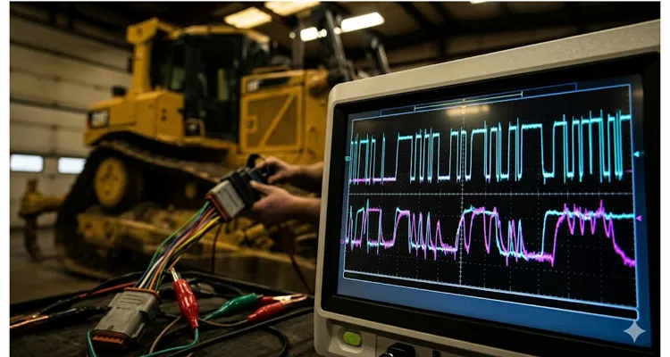
I hooked up a Picoscope with a breakout harness at the 9-pin Deutsch connector. Key on, engine off. The first thing I saw wasn’t the clean, sharp square wave I expected. The recessive state sat at 2.5V—fine. But the dominant edges sagged like they were fighting through treacle. Each transition looked less like a square wave and more like a discharging capacitor with no resistor to slow it. The differential waveform showed teeth that barely reached the minimum 1.5V threshold before collapsing.
That kind of waveform deformation isn’t a software bug. It’s a physical impedance problem. Somewhere in that network, the capacitance was too high, or the resistance was pulling the bus into a no-man’s-land.
We measured resistance across pins C and D with the master disconnect off. 63 Ω. That’s two 120 Ω termination resistors in parallel, reading correctly. But the scope told a different truth. On a hunch, I checked the bus impedance with a network analyzer while the module was still warm. At 250 kHz, the differential impedance measured 38 Ω instead of 60 Ω. That’s not a marginal error—it’s an active reflection generator sitting mid-bus, turning every frame edge into a slurred mess.
We started unplugging nodes one by one, watching the waveform. When we pulled the fuse for the aftertreatment control module, the signal snapped back to crisp, sharp corners you’d recognize from a benchtop demo.
Inside that module’s connector, behind the weather seal, we found the culprit: a single termination resistor inside the ACM housing had a cold solder joint that measured 63 Ω cold but drifted past 600 Ω when the module warmed up. At room temperature, it behaved. Ten minutes into operation, it created an impedance mismatch that reflected signals back down the bus, corrupting every frame. This is a textbook case of J1939 termination resistance drift hot vs cold — something we see regularly in the field.
A twenty-three-cent resistor. The repair cost less than the diesel we burned moving the machine into the bay. But finding it without a scope would have been a parts-swapping exercise that never ended.
What You’re Actually Looking At: The Anatomy of a J1939 Waveform
Before going further, we need to establish what a healthy bus looks like. If you don’t know what normal is, you’ll waste a day on phantoms.
J1939 runs on CAN 2.0B at 250 kbit/s. The spec says 40 meters max bus length and 4 µs nominal bit time, and it’s easy to read that and think “plenty of headroom.” But on a machine with a rear-mounted controller and a cab bulkhead connector, I’ve measured end-to-end harness resistance that pushed the time constant past 5 µs at -20°C. The spec assumes a clean lab bench; the machine does not. On a scope, I set my time base to 20 to 50 µs per division. Any slower and you’ll miss edge artifacts; any faster and you lose the message context.
Connecting Your Scope to the J1939 Diagnostic Connector
Connect your scope’s Channel A to pin C (CAN High) and Channel B to pin D (CAN Low). If your scope has math capability, configure a differential channel (A minus B). Ground each channel to pin E or a solid chassis ground—but only at one point. Creating multiple ground paths introduces ground loops that will pollute your measurement.
On a scope trace, I’m looking for corners that break cleanly—not right angles from a geometry textbook, but transitions that don’t ring more than once and don’t overshoot by more than a half-volt. Anything beyond that, and I start hunting the harness diagram. The differential signal should swing cleanly between zero volts (recessive) and at least 2V (dominant), though you’ll typically see around 2.3 to 2.8V in practice. The recessive differential voltage should sit within 50 mV of zero.
Identifying CAN Bus Shorts and Termination Faults from the Waveform
If you see CAN High and CAN Low moving in parallel rather than mirroring each other, you’re looking at a short between the two lines. If one channel is stuck near battery voltage, you have a short to power. If the differential peak-to-peak is below 1.5V, start checking termination, because the bus can’t reliably distinguish recessive from dominant states at that level.
One detail that textbooks often omit: a perfectly healthy bus at a cold-soaked startup in northern Minnesota will look slightly different from the same bus after eight hours of hard digging in Arizona. The CAN transceiver output voltage drifts with temperature, and the twisted-pair impedance changes slightly as the copper warms. A scope lets you account for this. An ohmmeter does not.
For a quantitative breakdown of acceptable edge rates, overshoot limits, and differential voltage thresholds from an oscilloscope perspective, I covered those in my J1939 scope bench edge rates ringing differential voltage guide.
Setting Up the Scope: What Matters and What’s Wasted Motion
I see technicians unbox a new scope, attach probes randomly, and then spend forty minutes chasing their own setup errors. This isn’t something you want to learn under the pressure of a machine that’s bleeding three thousand dollars an hour in downtime.
Probe Selection for J1939 Oscilloscope Diagnostics
I once spent an afternoon chasing a “noisy” CAN signal that turned out to be the 1x probe loading the transceiver with about 100 pF of extra capacitance. The waveform looked like a sawtooth, and I nearly condemned a perfectly good ECM. That’s now burned into my workflow: 10x attenuation, always, unless I’m deliberately measuring ripple on a sensor supply and need the sensitivity. If you’re using a differential probe, verify its common-mode rejection ratio before trusting the reading—especially on machines with welding or hydraulic solenoid noise nearby.
Trigger Setup for Capturing J1939 Start-of-Frame Pulses
The scope’s auto-trigger will happily show you a clean baseline while the bus is silent for 800 ms between messages. You’ll stare at a flat line and conclude the bus is dead. I set a falling-edge trigger on CAN High with a threshold around 2V right after power-on. That catches the start-of-frame dominant pulse every time. Use normal trigger mode and set a generous holdoff—around 100 µs—to prevent re-triggering on the same frame’s arbitration bits.
Sample Rate and Memory Depth for Heavy-Duty CAN Bus Analysis
You need at least ten megasamples per second to capture edge transitions cleanly on a 250 kbit bus. Faster is better, but memory depth matters more. A deep buffer lets you capture multiple frames in a single acquisition and scroll through to find intermittent faults. I typically set 5 to 10 ms of visible time and let the scope’s memory handle the rest.
Grounding Techniques to Eliminate Noise in J1939 Waveform Measurement
This is where most field measurements go wrong. The ground lead on a standard passive probe is an antenna. I’ve watched alternator whine swamp a trace simply because the alligator clip was draped across the intake manifold. Use the shortest ground spring clip you can, or better yet, solder a dedicated ground point onto your breakout box and use a BNC-to-banana adapter with a shielded path. The difference in noise floor is dramatic—from 200 mV of hash down to a near-invisible 10 mV.
If a persistent J1939 ground offset is already wreaking havoc across multiple modules, I’ve outlined the diagnostic workflow for that in a separate article.
Verification Step: Capturing a Known-Good J1939 Reference Waveform
Before diagnosing anything, probe a known-good node on the same harness and capture a few frames. Save that waveform as your reference. Now when you probe the suspect node or section of harness, you have an A-B comparison that eliminates variables like ambient temperature, battery voltage sag, or scope settings.
Five Waveform Patterns That Answer the Question Without Saying a Word
After looking at thousands of J1939 captures, I’ve stopped describing bus faults with textbook terms. I name them by what they look like on my screen, because the shape rarely lies.
The Weak Handshake: Missing or Drifted J1939 Termination Resistor
The CAN High and CAN Low traces try to move but can barely separate. Differential voltage sits around 800 mV to 1V. It’s the electrical equivalent of a limp handshake—there’s just not enough current drive to pull the bus dominant. Classic missing or drifted termination resistor. I had a wheel loader where the bus worked at idle but collapsed as soon as you raised the boom; the terminator in the rear controller had gone open, and the resulting 120 Ω single-ended impedance couldn’t charge the line capacitance fast enough. Check resistance at the diagnostic connector—if you see 120 Ω instead of 60, one terminator is MIA.
The Capacitor Ramp: Excess Capacitance from Untwisted Wire Splices
The dominant state doesn’t hold flat; it ramps upward like a charging capacitor. This usually means excess capacitance on the bus—sometimes from a module with a damaged internal decoupling cap, or a harness repair where someone spliced in a section of untwisted wire. Twisted pair maintains the 120 Ω characteristic impedance; untwisted sections add uncontrolled capacitance. On a combine harvester, I found a 15 cm splice where the tech had used parallel zip cord. That little section made every dominant bit look like a ski slope. Replace untwisted wire; don’t try to filter it out.
The Whip Crack: Impedance Discontinuity from Long Stubs on a J1939 Backbone
Sharp transitions followed by damped oscillation that rings for more than two cycles. It looks like a whip being cracked—a sudden pulse then a shudder. This is an impedance discontinuity, typically from an un-terminated stub or a branch longer than 1 meter. The spec allows 1 m stubs, but I’ve seen visible reflections starting at 60 cm on a 250 kbit bus. On an excavator with a cab-mounted display, the stub to the overhead panel was 1.8 m and produced a beautiful 8 MHz ring that corrupted every tenth frame. The fix was to re-route the backbone to include that node directly.
For the engineering rationale behind the 1-meter stub rule and how to calculate the exact reflection timing, take a look at our J1939 backbone termination stub length guide.And if you want to see what a chronic stub-length problem actually costs a fleet over a year, we broke down the real numbers in our analysis of phantom faults from poor termination and stub design.
The Wandering Neutral: Common-Mode Voltage Drift from Moisture or Resistive Shorts
The recessive voltage should sit at Vcc/2—about 2.5V on a 12V system—and stay within 20 mV. When it drifts, or shifts as you wiggle a connector, you’ve got a resistive short to ground or power pulling the common-mode voltage off-center. I chased an intermittent gauge flicker on a tractor for two days. The DMM always read 2.5V. The scope showed the recessive level creeping from 2.5V to 3.1V over 20 minutes, coinciding with moisture in the cab controller connector from a power-washer. That 600 mV common-mode creep was eating the entire noise margin. A DMM in averaging mode will lie; the scope shows the truth.
If you want the full oscilloscope measurement procedure for tracking down a common-mode voltage shift, I broke it down step-by-step in my J1939 common-mode voltage shift measurement guide.For a deeper dive into diagnosing ground offsets specifically through common-mode voltage behavior, our guide on J1939 common-mode voltage and ground offset diagnosis walks through that process.
The One-Way Conversation: Missing ACK Bit on a J1939 Frame
After the CRC delimiter, there’s a two-bit acknowledge slot. If you see a frame transmit cleanly but the ACK bit remains recessive—no node pulls it dominant—then the message is talking to an empty room. This can be a configuration mismatch (wrong PGN, wrong source address), or the only other node on that virtual network is powered down or dead. On a generator set, the engine ECM was broadcasting, but the control panel was in a sleep mode. The waveform otherwise looked perfect. A missing ACK isn’t a physical layer fault; don’t chase it with an ohmmeter.
Here’s how these patterns look side-by-side in the field:
| Pattern | Scope Symptom | Root Cause | Common Fix | Real-Machine Example |
| The Weak Handshake | Diff voltage <1V, sluggish edges | Missing/drifted termination resistor | Replace or re-seat terminator | Wheel loader boom movement killed bus |
| The Capacitor Ramp | Dominant state ramps up | Excess capacitance (bad splice) | Replace untwisted wire | Combine with zip cord splice |
| The Whip Crack | Ringing >2 cycles after edges | Stub longer than 1m | Re-route backbone, eliminate stub | Excavator overhead panel stub |
| The Wandering Neutral | Recessive voltage drifts over time | Resistive short to gnd/power | Clean connector, fix moisture ingress | Tractor after power-washing |
| The One-Way Conversation | Clean frame, recessive ACK bit | No receiving node | Check node power, address config | Genset with sleeping panel |
The R.I.S.C. Method: A Diagnostic Sequence That Doesn’t Waste Your Time
When a J1939 network is down and the machine is hemorrhaging money, the pressure to start swapping parts is immense. Resist it. I’ve boiled my diagnostic sequence down to an acronym I teach new techs: R.I.S.C.—Resistance, Inspect, Scope at midpoint, Check under load. Follow this, and you’ll find the fault faster than the guy with the laptop full of diagnostic software.
Inspect the Diagnostic Connector and ECU Connectors for Physical Damage
Before probing anything, look at the diagnostic connector and any accessible ECU connectors. Check for pushed-back pins, green corrosion creeping up the wire strands, or seal damage that let moisture into the backshell. A J1939 backbone can survive a surprising amount of environmental abuse, but water ingress into a connector body creates an electrolytic cell that eats copper at the crimp. No scope can fix a dissolved wire.
Resistance Check Under Three Conditions for J1939 Termination
Measure resistance across CAN High and CAN Low with the master disconnect off. Then measure it with the disconnect on but the ignition off. Then measure it with the ignition on. These three numbers must all be 60 Ω plus or minus 5. If the resistance changes between states, a module’s internal termination is switching in and out, or a transceiver is partially shorted and pulling the bus low only when powered.
Scope Capture at the Backbone Midpoint to Reveal Hidden J1939 Faults
If the resistance checks pass, move to a scope capture at a junction block near the middle of the backbone. This midpoint gives you the worst-case reflection scenario and will reveal problems that nodes at either end might mask. Capture 500 ms of bus activity and look for any frame that doesn’t end with a clean recessive state.
Systematic Node Isolation and Harness Load Testing for CAN Bus Diagnosis
Start systematic node isolation. Remove modules from the bus in order of their distance from the diagnostic connector, and re-capture the waveform after each removal. When the waveform suddenly cleans up, the last module removed is your primary suspect. But here’s the nuance: the fault could be in the harness section leading to that module, not the module itself. Re-connect the module and disconnect the next upstream junction. If the waveform stays clean, the harness segment is the culprit. Then, load-test that segment. A wire that passes a continuity test with a DMM’s microamp current can still fail under the milliamp load of a CAN transceiver. Use a load-pro or a resistor network to pull about 100 mA through the suspect CAN High and CAN Low wires while monitoring voltage drop. Any drop over a few hundred millivolts indicates high resistance—usually from a corroded splice or a pin that’s been bent and is only making contact on a razor-thin edge.
Dynamic Validation: Thermal Cycle and Vibration Test for J1939 Repair
Once you’ve identified and repaired the fault, don’t just clear the codes and call it fixed. Run the machine through a full thermal cycle—cold start to full operating temperature—while capturing waveforms every ten minutes. Intermittent faults are lazy; they only show up when the harness is vibrating at 1800 RPM or when the connector body has expanded just enough to break a marginal crimp. I’ve had machines leave the shop only to return three weeks later with the same fault because I skipped this step. Now the rule is: it doesn’t leave until I’ve loaded every solenoid and wiggled every connector while the scope rolls.
For hunting down intermittent opens that only appear under flex, the wiggle test protocol for J1939 harness opens is a technique worth adding to your routine.
Mistakes I’ve Made So You Don’t Have To
These aren’t from a manual. These are things I have personally gotten wrong, and the machines didn’t let me forget it.
Measuring Resistance with the Bus Powered: A J1939 Diagnostic Blunder
A CAN transceiver has internal biasing circuits that become active when powered. I fried the ohms circuit on my old Fluke 289 doing this on a Deere 644K hybrid. Now the rule is: master disconnect pulled, key cycled to drain any caps in the DC-DC converter, then measure.
Assuming the Diagnostic Connector is the Backbone: The 3.2-Meter Stub Trap
The 9-pin Deutsch connector is a convenient access point, but on many machines it hangs off a stub that can be several meters long. On a certain wheel loader, the cab’s 9-pin connector sits on a 3.2-meter stub. Probing there showed ringing that looked like a dead terminator. I spent a day chasing a phantom until I opened the rear junction box and scoped the backbone directly—clean as a whistle. Now I always check the wiring diagram before trusting the diag port’s waveform.
Using a Single-Ended Measurement for a Differential CAN Signal
I still see seasoned techs probe only CAN High relative to ground and declare the bus healthy. A single-ended measurement can’t show common-mode noise or a CAN-H-to-CAN-L short. On a dozer with a flickering display, the CAN-H and CAN-L were shorted together but both floated at 2.5V to ground—a meter saw nothing. A differential channel instantly showed zero amplitude. It’s non-negotiable.
Ignoring the Baud Rate Setting on an Oscilloscope for J1939 Decoding
Scopes with protocol decoding need to be told the network speed. J1939 runs at 250 kbit, but I wasted half a day on a dozer decoding gibberish because the scope was left at 500 kbit from a previous passenger-car job. The waveform looked fine, but the decoder spat out nonsense. Now I double-check the baud rate before every capture.
Neglecting the Shield on a J1939 Harness: Ground Loops and EMI
J1939-11 specifies a shielded twisted pair, with the shield grounded at a single point. On a generator with a VFD nearby, the shield was floating, turning the entire harness into an antenna. The scope’s FFT showed 8 kHz spikes exactly matching the VFD’s PWM frequency. Grounding the shield at one end silenced it. I’ve also seen the opposite—shields grounded at both ends, creating a ground loop that injects alternator whine directly into the signal. Don’t ignore the shield just because the bus “mostly works.”
If you’re dealing with PTO-related noise specifically, I’ve detailed the shielding and filtering approach in my PTO J1939 interference diagnosis shielding filtering article.
How to Confirm the Repair Stuck
A bus that works at key-on in a quiet shop hasn’t proven anything. I use a three-stage confirmation that’s kept warranty returns off my desk.
Stage 1 – Baseline Waveform Capture After J1939 Repair
First, capture a baseline waveform of the repaired bus at idle and verify the differential amplitude exceeds 2V with clean edge transitions. Save this waveform—it’s your insurance policy if the machine returns with the same symptoms.
Stage 2 – Frame Stress Test to Verify J1939 Bus Throughput
Second, perform a “frame stress test.” Use a diagnostic tool to transmit a high-priority message at maximum frequency—typically a request for engine speed at 10 ms intervals—while capturing on the scope. The bus should handle the traffic without any recessive-level drift or edge degradation. If it can’t handle maximum load in the shop, it won’t survive a real-world duty cycle.
Stage 3 – Full Electrical Load Test to Detect EMI Coupling into the J1939 Network
Third, and this is the one nobody does, check the waveform with every electrical load on the machine turned on simultaneously: lights, AC compressor, wipers, every solenoid that can be energized. Turn them on and off while the bus is active, and watch the scope for any noise coupling. A harness that routes CAN twisted pair too close to unfiltered solenoid wiring will show voltage spikes on CAN High and Low that coincide with solenoid switching events. That kind of intermittent noise is a warranty claim waiting to happen six months from now, when a solenoid driver starts failing and injecting enough EMI to garble a frame once every ten thousand cycles.
When all three stages pass, I’m comfortable releasing the machine. Until then, the scope stays connected.
The Tools That Make This Work Possible in the Field
Not every oscilloscope is suited for heavy-duty diagnostics. I’ve used bench scopes that cost more than a used pickup truck, and I’ve used handheld units that cost less than a set of injectors. For J1939 work, you need two things above all else: a genuinely isolated input stage that can handle a hundred-volt common-mode surprise without frying, and a decoder that actually understands 29-bit identifiers.
I keep a breakout box in the truck that I soldered a BNC ground post into years ago. It’s ugly, but it eliminates ground-loop headaches. If you don’t have one, we build them to spec. We make diagnostic breakout harnesses and interface cables specifically for this environment—ones that survive being crushed under a cab floor plate and don’t corrode when left in a damp toolbox. If you’re setting up a dedicated diagnostic kit for your shop, or if you’re an equipment distributor looking to standardize your field service tooling, we engineer these solutions from scratch based on the connectors and protocols your fleet actually uses. No universal-fit compromises.
Whether you need a custom 9-pin Deutsch to BNC breakout that lets you scope the backbone without piercing wires, or a full interface cable with a sealed PC connection for remote data logging, we handle the OEM engineering and build it in-house. Twenty-plus years of cable manufacturing means the crimp quality, the jacket material, the pin retention—all the things that fail on commodity cables after six months on a vibrating chassis—are engineered out from the start.
Frequently Asked Questions from the Shop Floor
Do I really need a scope, or can I diagnose J1939 with just a multimeter?
A multimeter will catch a dead short or open. But if the bus is “sometimes” dead, you need a scope. I wasted three days on a dump truck that would derate only after 40 minutes of run time. The meter showed 60 Ω and 2.5V. The scope showed the recessive level drifting as the DEF tank heater cycled. No meter could catch that. There’s no middle ground.
What bandwidth scope is sufficient for J1939?
I keep an old Tektronix THS720P in the service truck—20 MHz, isolated channels, built like a brick. It’s never been the bottleneck. The times I’ve been stuck were always memory depth, not bandwidth. A cheap USB scope with 2M samples per channel will let you scroll through 500 ms of bus traffic. That’s worth more than 100 MHz on paper.
Can I use a two-channel scope effectively?
Yes. Set Channel A on CAN High, Channel B on CAN Low, and use the math function for differential. A four-channel scope is nice for capturing additional signals—say, a synchronization pulse from a known-good sensor to correlate bus activity with engine position—but it’s a luxury, not a necessity for most diagnostic work.
Why does my bus work fine when I unplug one module but fail when it’s connected?
The module’s internal bus termination is probably switched in when the module is powered, creating a double-termination scenario at one end of the bus. Instead of 60 Ω, you get 40 Ω at that node, and the resulting signal amplitude drops below the receiver’s detection threshold. Measure the module’s CAN pins with it disconnected and powered off. If you see 120 Ω, it’s a terminated node and must be at the physical end of the backbone—not somewhere in the middle.
What does a “corrupted” J1939 waveform look like versus a “legitimate” bus collision?
A bus collision—where two nodes transmit simultaneously and arbitration occurs—looks like a normal frame because it is a normal frame; the higher-priority message wins cleanly. A corrupted frame shows non-physical edges, voltages that don’t reach valid dominant levels, or frames that abruptly truncate. On a tractor, I saw clean edges and correct voltages, but the decoder flagged CRC errors on every other frame. It turned out the engine ECM had been re-flashed with a slightly different PGN configuration. Physical layer perfect, protocol mismatch. If the decoder shows consistent CRC errors but the waveform looks clean, suspect a configuration mismatch, not a physical fault.
How often should the bus termination resistors be checked?
I make it a habit during every PM. Thirty seconds at the 9-pin connector. I write the value in the service report. If it creeps from 60 to 63 to 68 over three services, I know there’s a connector with green fuzz hiding somewhere. Catch it before it becomes a field failure.
Is CAN bus diagnostics different for agricultural versus construction equipment?
The protocol is identical. The physical environment is different. Agricultural equipment sees more chemical exposure and rodent damage. Construction equipment sees more physical abrasion from vibration and debris impact. The diagnostics are the same; the harness locations where you’re most likely to find damage differ. On a combine, I start at the hinge point for the unloading auger—it flexes hundreds of times a day. On an excavator, I go straight to the boom foot where the harness rubs against the pin.
Can a faulty battery or charging system cause J1939 communication issues?
Indirectly, yes. If the alternator is producing excessive ripple—anything over about 100 mV AC on a 12V system—that ripple can inject into the CAN bus through modules with poor internal filtering. I once chased a derate for a week before finding the alternator ripple at 2.4V AC. The modules were spending so much time error-checking that throughput dropped to a crawl. Check the charging system before condemning the data link.
What’s the most common J1939 fault you see?
Of the last hundred J1939 calls I’ve worked, water intrusion claimed 42 of them—not module failures, just connectors that someone forgot to grease. Nineteen were untwisted wire splices. Twelve were drifted termination resistors. The remaining are the weird ones that keep life interesting. Electronics modules themselves are rarely the root cause—maybe one in twenty ends up being an internal transceiver failure.
Where can I get custom diagnostic cables built to my fleet’s specifications?
That’s what we do. Our engineering team works with fleet managers and OEMs to design diagnostic interface cables with the exact connectors, pinouts, and jacket materials required for specific applications. Whether you need a single diagnostic breakout or a production run of interface cables for your service network, we build to your specifications. Reach out through the contact page or message me directly on WhatsApp—I prefer to have a real conversation about what you’re trying to accomplish before we quote anything.
Need Something Engineered for Your Diagnostic Workflow?
This article walked through what we see in the field every day. If you’re dealing with a persistent J1939 issue that doesn’t match any of the patterns here, or if you need custom diagnostic cabling built to survive your fleet’s operating environment, we can help.
We manufacture breakout harnesses, interface cables, and diagnostic adapters under ISO 9001 and IATF 16949 quality systems. Every assembly goes through a four-step inspection process before it leaves our climate-controlled, ISO 14001-certified production floor. We support full OEM customization—your logo, your cable spec, your connector selection, your color coding. Nothing that ships carries our branding unless you want it to.
For technical support or to discuss a custom project: Contact us here or message me directly on WhatsApp. I prefer to discuss the application in detail before we build anything—it saves time and ensures what you receive actually solves the problem.
