

The scope’s fan had been humming for 34 minutes when the glitch finally appeared – a single recessive spike stretching to 1.8V for 800 microseconds, then gone. The truck idled through it like nothing happened. The ECU error counter didn’t even twitch. That’s when I learned: the problems that cost fleets the most money are the ones the protocol’s own fault confinement never sees. If you’re reading this, you probably know the feeling. What follows isn’t a textbook summary. It’s field notes — the kind you keep in a battered notebook, not a glossy training manual.
A J1939 network that works just well enough to avoid permanent fault codes but collapses under load is far more dangerous than a hard failure. Intermittent address claims, ghost fault codes, a derate that vanishes after a key cycle — these eat diagnostic hours and erode trust between fleets and service bays. The scope rarely lies, but it demands you learn its dialect. Three parameters reveal almost everything: differential voltage, edge transition time, and what engineers in the field call “ringing.” This is how I read them, on real machines, with real stakes.
The Scene Where It All Goes Wrong
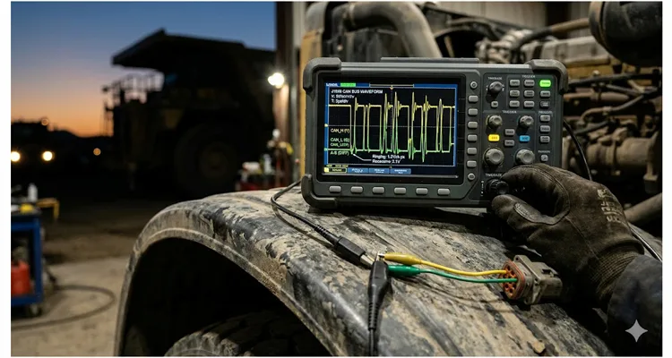
Last winter, a 2021 model-year off-highway truck rolled into our engineering support bay with a complaint that nobody had pinned down for 11 months. The engine would sporadically drop to idle during loaded ramp climbs. No MIL, no permanent DTC. The OEM’s field tech had replaced the ECU, the engine harness, and three injector trim resistors. The problem remained. The bill was approaching $17,000 in parts alone. That’s when I propped my scope on the fender and clipped onto the J1939 backbone — pins C and D at the diagnostic connector.
The first trigger event showed a recessive differential voltage sitting at 1.8V instead of the expected 2.5V. That’s not a failure that flags an error counter. The transceivers can still interpret dominant versus recessive, most of the time. But when the bus loaded up with torque commands, the noise margin collapsed.
This is what separates component-swapping from diagnostics: you chase what the signal almost lost, not what it lost completely.
Differential Voltage: What the ECU’s Error Counters Won’t Tell You
In that off-highway truck, the differential sat at 1.8V recessive – not a failure by the SAE spec, which cares about a 1.5V dominant differential voltage threshold. The spec says the bus was healthy. The pile of replaced parts said otherwise. That’s the gap I work in every day.
The SAE spec gives you a floor: 1.5V dominant differential, measured at the silicon. But by the time that signal travels 40 meters of backbone, passes through six bulkhead connectors, and reaches the diagnostic port, I’ve yet to see a trouble-free J1939 bus that doesn’t show at least 2.0V dominant and a recessive quieter than 200 mV. When a machine comes in with 1.7V and the owner says “it just started acting up,” I already know I’ll find something the datasheet isn’t going to warn me about. When the recessive differential starts drifting upward — 0.8V, 1.2V, 1.8V — you have a termination problem, a ground offset between nodes, or a transceiver stubbornly holding the bus in a biased state.
Ground Offset Diagnosis on J1939 Networks
In the off-highway truck case, both 120Ω terminating resistors measured fine cold. The issue was the ground reference. The engine ECU’s ground stud had been powder-coated over during a frame repair, and the ring terminal was making contact through a thread’s worth of oxidized steel. That lifted the ECU’s local ground by 0.7V relative to chassis. On a 2.5V recessive baseline, 0.7V of offset eats nearly a third of your noise margin. The scope showed it immediately: CAN_H and CAN_L both shifted upward by the same offset, keeping the differential small but squeezing the absolute voltage rails toward the transceiver’s common-mode limit.
Check ground offsets before you condemn a transceiver. I measure voltage between ECU ground pins and battery negative with the system under load. Anything over 100 mV gets a hard look. Over 300 mV? Stop diagnosing anything else until it’s fixed.
Edge Rates: Finding the Slant That Swallows a Bit
On a PicoScope 4425A, set to 200 ns/div, a healthy J1939 transition looks like a cliff. This one looked like a boat ramp.
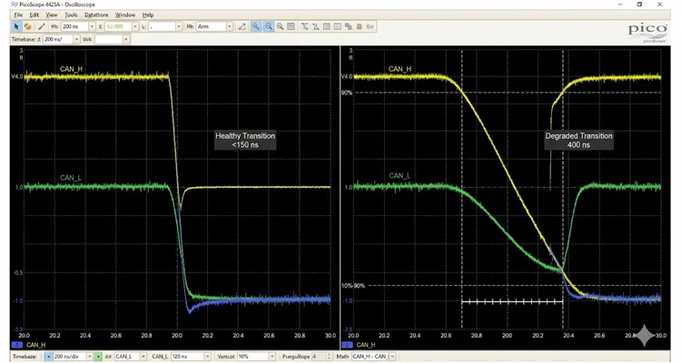
I once traced a 400 ns edge to a 2.5-meter unshielded pigtail that a service truck had spliced onto a load cell sensor node. The splice used gel-filled crimps rated for trailer lighting, not 250 kbit/s CAN bus. The added capacitance rounded the leading edge just enough that the sampling point — typically at 60–75% of the bit time — fell during the transition rather than in the stable region. The result was intermittent bit errors that occurred only above 40°C ambient, when the transceiver’s drive strength thermally derated.
J1939 runs at 250 kbit/s. At that speed, a bit time is 4 µs. A typical transceiver like the TJA1040 or ATA6560 switches from recessive to dominant in 50–100 ns. On a scope, that’s a vertical line. When you start seeing slopes of 300 ns, 500 ns, or worse, something is loading the bus capacitance beyond what the transceivers can drive. J1939 edge rate degradation rarely appears uniformly across all nodes. It usually shows up worst at the mid-point of a long stub, or at a node where someone spliced in a repair section with mismatched twisted-pair geometry.
Stub Wiring and Capacitance Effects on Edge Rates
Measure edge time between 10% and 90% of the full differential swing. On a healthy J1939 bus, I want to see under 150 ns. If I see 200 ns or more, I start unplugging nodes until the edge snaps back to normal. The last node you disconnected before it recovered? That’s your culprit — or at least its stub wiring.
Ringing: Not Fuzz, It’s a Bit Timer
I’ve had a service manager tell me, straight-faced, “A little fuzz on the waveform is normal, the error handling sorts it out.” The same machine had logged 47 bus-off events in 12 engine hours. Ringing isn’t fuzz. It’s a timer that sets the bit error rate – and if the first overshoot chews into the sampling point, the protocol’s error frames become a full-time job.
A small amount of damped oscillation after a dominant-to-recessive transition is expected, especially on long J1939 backbones with multiple nodes.
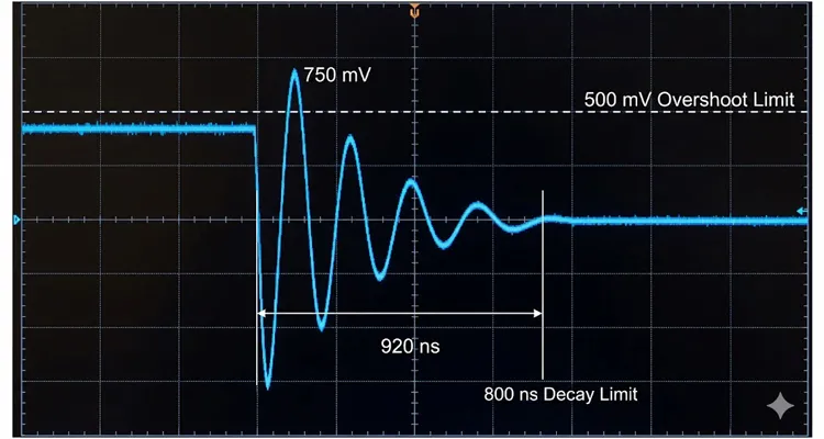
But when the amplitude of the first overshoot exceeds 500 mV peak-to-peak on the differential waveform, or when the ringing persists beyond 30% of the bit time, you’ll see recessive bits misinterpreted as dominant. That generates form errors, CRC errors, and eventually the controller goes bus-off.
How Ringing Triggers Bus-Off Events in J1939 Systems
The root causes I encounter most often: missing termination, mismatched impedance caused by daisy-chaining nodes with different cable characteristic impedance, or a node with an integrated termination that wasn’t disabled when it moved from the end of the backbone to a middle drop. One harvesters manufacturer had a production run where the termination resistor was populated on every node PCB by mistake, not just the end nodes. At the assembly line, the bus worked because the total resistance was low enough. In the field, after two resistor failures open-circuited, the remaining parallel resistance became erratic, and the ringing amplitude triggered sporadic bus lockups. The waveform looked like a tuning fork.
A quick check: measure the bus resistance with everything powered down, between CAN_H and CAN_L. You’re aiming for roughly 60Ω (two 120Ω terminators in parallel). If you read 40Ω, there’s at least one extra terminator hiding somewhere. If you read 120Ω, one terminator is missing. More than 120Ω? Both are missing, and the bus is flying on hope.
Step-by-Step: How I Approach a Suspect J1939 Signal
- I start with a dead bus resistance check. Key off, battery disconnected. My Fluke 87V between CAN_H and CAN_L at the diagnostic connector. I’m looking for 60Ω ± 10Ω. If I get 40Ω or 120Ω, I don’t even hook up the scope until every terminator is physically located and verified.
- I power up the bus and immediately save a baseline trace to a USB stick. Folder name: CustomerName_Date_ColdStart. I use a TA043 differential probe for the preliminary pass – it rejects the alternator whine that creeps in when I forget to isolate the scope power supply. I set the timebase so I can see five full frames, not just one: 200 µs/div. That’s enough to catch a pattern without zooming past a standing offset. I check recessive differential voltage – should be under 200 mV – and dominant, which must exceed 2.0V on a typical 12V system, with CAN_H swinging toward 3.5V and CAN_L toward 1.5V.
- Then I zoom to one dominant-to-recessive transition at 200 ns/div. On the Picoscope, I use the automated measurement for 10-90% fall time but verify with cursors because the measurement gating can be fooled by a noisy baseline. A healthy J1939 transition settles within 200–300 ns with less than 300 mV overshoot.
- Introduce bus load. Start the engine, activate high-traffic PGNs — torque, wheel speed, transmission states. Watch the waveform density. Look for any recessive differential voltage drift that correlates with RPM or hydraulic load. That drift is often a ground dance.
- Isolate with node removal. Unplug nodes one at a time while monitoring edge rate and ringing. If a node removal sharpens edges or reduces ringing, you’ve found either a problematic transceiver or a stub topology that’s creating reflections.
- Probe individual stubs. Many techs scope the backbone only. Stubs hide sins. Check the waveform at each node’s connector, where the stub meets the PCB. You’ll sometimes see ringing amplitude that never reaches the backbone but corrupts that specific node’s receive path.
- Record, don’t just look. Use the scope’s persistence mode or segmented memory to capture infrequent events. I let it run for 20–30 minutes while I drink coffee. The one frame with a 1.2V recessive spike won’t appear on a single sweep.
Five Mistakes I See Repeatedly in J1939 Diagnostics
- Scoping only CAN_H or CAN_L single-ended. A technician in Brisbane sent me a screenshot of a pristine CAN_H trace and a CAN_L that looked like a seismograph during an aftershock. He’d spent two days chasing a phantom transmission fault because his scope was single-ended. The differential math – just CH1 minus CH2 – revealed 2.3V of noise riding on both lines in common mode, invisible on the single trace. That’s the day I stopped allowing single-ended as a first-pass method.
- Ignoring ground offsets during scope setup. I once clipped the ground lead to a lifting eye that looked clean but had a coating of road grime. The resulting 150 mV offset had me convinced the ECU was failing. I always ground to battery negative directly or to a verified clean chassis stud now.
- Testing only at key-on, engine-off. Many noise sources are silent until the alternator, injectors, or hydraulic solenoids are active. A bus that looks perfect in the shop can deteriorate within 30 seconds of engine start. I remember a combine that only threw CAN errors when the header clutch engaged. At idle in the bay, the bus was textbook. Test under worst-case electrical noise conditions: high beams, blower motor, wipers, full hydraulic demand.
- Assuming the J1939 terminating resistors are at the ends of the backbone. Physical location trumps schematic assumptions. On a forestry skidder, I found a terminator taped inside a wire loom behind the cab, not at the far end of the implement bus. That’s why the bus worked – until the loom got wet. I’ve also found them stuffed inside a folded rubber mud flap. Find them physically and verify their connection integrity.
- Replacing a node without checking its bus pins at the connector. Bent pins, pushed-back terminals, and partially seated connectors cause more CAN faults than failed silicon. Before I ever condemn a controller, I run a drag test with a spare Deutsch pin. I’ve stopped counting how many “failed ECUs” had a pin just a millimeter deeper than spec. A 10-second visual inspection and pin drag test saves replacing a $1,200 controller that was never faulty.
How to Confirm the Repair Is Real
Passing no comm errors in a 10-minute engine idle isn’t confirmation. I run a specific sequence:
- Drive the vehicle or operate the machine through a full thermal cycle — cold start to full operating temperature — while logging CAN bus error counters with a CAN interface tool (PCAN, Vector, or equivalent).
- The transmit and receive error counters must stay at zero for the entire cycle. Even one increment on a single node’s TEC tells you something isn’t fully resolved.
- Re-scope the recessive differential voltage and edge time under load at the node that was previously at fault. The waveform should overlay near-perfectly with a known-good baseline recorded earlier.
- Perform a wiggle test on every connector in the bus path while watching the scope in persistence mode. If the trace fractures, that connector needs terminal replacement, not just reseating.
Only when the error counters are zero across a thermal cycle and the waveform withstands physical manipulation do I close the job. Anything less invites a repeat visit.
Related Products That Support Reliable J1939 Networks
The quality of the J1939 physical layer components matters as much as the diagnostic approach. On our production floor, we build J1939 backbone harnesses, stub assemblies, diagnostic breakout cables, and custom CAN termination plugs for heavy-duty equipment, marine, and off-road applications. Every assembly goes through a 4-step inspection: 100% continuity and short-circuit testing, differential impedance verification on a network analyzer, physical pull-test on crimps, and a final visual under 3x magnification. We use only RoHS-compliant, full-plastic connector shells with UV-stabilized materials — no recycled regrind that turns brittle in two seasons.
Our engineering team regularly designs custom-length J1939 cables with specified AWG, precisely controlled twisted-pair geometry, and integrated terminating resistors built to the exact characteristic impedance for the CAN bus physical layer. We support OEM branding, custom color coding by network (powertrain vs. implement bus, for example), and packaging that follows 5S-managed, climate-controlled warehousing. ISO 9001, IATF 16949, and ISO 14001 certifications apply to our entire production line. If you’re maintaining a mixed fleet where no two machines share the same J1939 network topology, or you’re an equipment builder needing harnesses that won’t generate phantom CAN bus faults, we can discuss your specific electrical and mechanical requirements.
FAQ — Quick Answers from the Scope Bench
I’m seeing 1.8V dominant at the diagnostic connector – is that too low for a 12-node J1939 system?
On the J1939 backbone at the diagnostic connector, 2.0V minimum under load. If you measure at a node’s stub connector, expect slightly lower, but not below 1.7V. At 1.8V on the backbone, I’d already be looking for a ground offset or a tired transceiver dragging the bus down.
Can a standard multimeter catch a bus problem, or do I really need a scope?
For resistance and static voltage checks, yes. For signal integrity — edge rates, ringing, transient offsets — no. A digital multimeter averages and updates slowly. It won’t show you a 500 µs glitch. A scope with decent bandwidth is non-negotiable once the easy checks are done.
How do I know if the ringing on my waveform is a problem or just normal noise?
If the first overshoot exceeds 500 mV peak-to-peak on the differential trace, or ringing persists beyond 800 ns after the transition, it’s interfering with bit sampling. Correct the J1939 impedance issue. Normal ring-down should settle within a few hundred nanoseconds and stay under 300 mV.
My scope’s voltage readings don’t match the OEM troubleshooting guide. What am I missing?
Check your probing ground reference. Also verify whether the guide specifies differential or single-ended measurements. This is a common source of misdiagnosis. I’ve seen a 0.5V discrepancy just from a ground clip on a painted bracket.
Why would a terminating resistor measure fine cold but cause problems after the machine warms up?
Carbon film resistors can drift in value at higher temperatures. I’ve measured J1939 terminators that read 120Ω at 25°C and 220Ω at 80°C. That’s enough to cripple a bus under load. When in doubt, swap to metal film or check resistance with a heat gun on the terminator body.
Unplugging one specific node makes everything work again. Do I replace that controller?
Not necessarily. The node’s stub harness could be causing an impedance mismatch, or the node’s termination may be incorrectly enabled. Investigate the stub first before replacing the controller. I’ve saved plenty of ECUs by simply correcting the stub length or disabling an integrated 120Ω resistor.
Our machine seems to run OK with only one terminating resistor. Is two really necessary?
It might, for a while, in a lab environment. In the field, with vibration, temperature swings, and electrical noise, a single termination results in reflections that eventually cause error frames and bus-off events. Don’t let a machine strand itself just because it limped along for a week.
I need to scope the CAN lines but I’m afraid of damaging the harness connector. What’s the safest way?
Use a J1939 diagnostic breakout box or a Y-cable that provides easy probing points. Back-probing connectors directly is acceptable but requires care to avoid terminal damage. I prefer a breakout box when I can; it pays for itself in prevented connector repairs.
Should I invest in a differential probe, or is two-channel math good enough for J1939?
Two channels with math works if your scope has sufficient bandwidth (100 MHz or higher) and you match the probes. A true differential probe is more accurate and immune to ground loop errors introduced by your scope’s power supply. I use both, but in a noisy environment I trust the dedicated diff probe more.
Our J1939 network drops out only when it rains. Where do I even start looking?
Start at the connectors that face water spray. Look for green oxide on terminals, cracked seals, and wicking paths along the wire insulation into the back of the connector. CAN bus signals are low-power; a 5 kΩ leakage path to ground from moisture is enough to bias the recessive voltage into the unreliable zone. I’ve chased enough rain-only bugs to keep a magnifying glass and contact cleaner in my roadside kit.
If You’re Chasing a CAN Problem Right Now
I know the pressure of a machine down on a job site, with a line forming behind it. If you’ve got a waveform that doesn’t make sense, or you’re stuck between suspecting the harness and suspecting a controller, send me the details. Our engineering team works with service technicians, fleet managers, and equipment builders to unravel CAN bus faults and design physical layers that don’t generate phantom problems. We can discuss custom J1939 harness solutions, OEM-specific configurations, or just go over your scope captures to help you isolate the root cause.
Reach out directly on WhatsApp for a conversation with our engineering support: Chat on WhatsApp
For formal inquiries, spec sheets, or to discuss an OEM project, use our contact page: Contact Us
We don’t sell off-the-shelf prices on the site because every harness we build is matched to specific backbone lengths, AWG, connector sealing, and branding requirements. When you reach out, we’ll talk about your exact J1939 topology — number of nodes, maximum stub length, environmental sealing needs — and work from there. No generic BOM, no boilerplate quotes. Just the physical layer designed the way it should have been from the start.If you’re working through a specific waveform anomaly and need a structured diagnostic workflow, our step-by-step J1939 waveform analysis guide walks through a real Kenworth T680 case from first capture to confirmed repair — including the five waveform features that separate a wiring fault from a condemned ECU.
