

Last November, a customer contacted us convinced his J1939 network was cursed. Six ECUs on a 250 kbps backbone, and the transmission controller would vanish from the bus every twenty to forty minutes. No obvious fault codes. Termination resistors measured spot‑on. The cable impedance fell within spec. The bit timing registers were copied straight from a known‑good system.
Three days of digging later, the culprit revealed itself: a 42‑nanosecond timing skew that a logic analyzer never even saw.
What follows is the real account—a failure that wears the mask of a software bug but lives entirely in the copper and the dielectric of your harness. This is a classic J1939 bit sampling error—the kind of ghost fault that drains fleet budgets while leaving nothing behind in the DTC logs.
The Field That Would Not Stay Up
Here is exactly what we walked into: a J1939 network running at 250 kbps with six nodes, a 38‑meter backbone, and one stub that the installer described as “about a meter.” Resistance across the bus read 60 ohms—precisely what two 120‑ohm terminations in parallel ought to read. Idle voltages sat at 2.5 V on CAN_H and CAN_L. Every field‑service checklist would have declared this bus healthy.
Yet the transmission ECU repeatedly fell into bus‑off. The TEC would drift upward from zero to roughly 170 over the course of half an hour, then vault past 255 in a matter of seconds. A watchdog reset would yank the ECU back onto the network, and the whole cycle would begin again.
If you ever encounter that signature—long intervals of apparent stability punctuated by rapid‑fire failure cascades—stop chasing the protocol stack or the application code. Look at the physical layer. Look at the copper.
What 42 Nanoseconds Actually Does to a 250 kbps Bus
Let’s anchor this in real numbers. At 250 kbps, a single bit time spans 4 microseconds—4,000 nanoseconds. The CAN controller samples each bit near 87.5% of that window, or 3,500 nanoseconds after the bit edge. That leaves a 500‑nanosecond cushion before the next bit begins. The J1939 standard presumes your bus edges have already settled by then.
What the standard does not tell you is that the 87.5% sampling point everyone hard‑codes into their registers assumes the edges clean up within the first 200 nanoseconds. Our edges were still ringing at 50 nanoseconds.
Forty‑two nanoseconds may sound like background noise. It’s roughly 1% of the bit time and about 8% of your post‑sampling safety buffer. But critically, it’s enough delay for a reflected edge to reach one node after it has already sampled—and before another node on the same J1939 bus makes its decision. Two ECUs, same bit, opposite logic readings. That’s the bit error your multimeter will never show you.
The Physics: Why a 1.8‑Meter Stub Broke a Perfectly Good Network
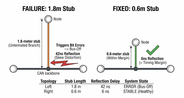
That “about a meter” stub measured 1.8 meters once we pulled back the loom and put a steel tape to it. Under the SAE J1939 standard, J1939‑11 caps the maximum stub length at 1 meter for 250 kbps operation.
Every meter beyond that introduces roughly 5 to 6 nanoseconds of additional propagation delay. If you’re not familiar with proper backbone and stub topology, our comprehensive J1939 backbone and stub length guide walks through the exact layout requirements.
A 1.8‑meter stub is an unterminated transmission line branch. When a node drives the bus, the signal races down the stub, hits the backbone junction, and splits. Part of the energy continues along the backbone; part of it bounces straight back. The round‑trip time for that first reflection is:
1.8 m × 2 × 5 ns/m = 18 ns
That’s merely the first bounce. Reflections do not politely stop. The second round trip adds another 18 ns (now 36 ns). The third edge arrives near 54 ns.
Meanwhile, the CAN transceiver flips from dominant to recessive, and its source impedance rockets from roughly 50 Ω to nearly 60 kΩ. That’s a brutal mismatch against the 120 Ω characteristic impedance of the CAN bus, and it’s exactly what keeps those reflections ringing.
In our customer’s system, the transmission ECU was absorbing voltage perturbations between 18 and 54 ns after the nominal edge. At 250 kbps, edges ought to settle within a couple hundred nanoseconds. Ours were still wobbling 50 ns in. The node nearest the stub junction sampled at 3,500 ns—theoretically long after the ringing should have subsided. But the ECU at the far end of the backbone saw a completely different waveform; its transceiver still had residual ringing when its own sampling window opened. Same bit. Opposite verdict.
Bit error. TEC +8. Repeat.
This is precisely the kind of fault we detail in our J1939 stub length phantom fault cost analysis. A stub that’s 80 centimeters too long can quietly bleed your fleet of thousands of dollars in diagnostic hours.
Why the Error Counters Turn a Small Problem Into a Bus-Off
Every CAN controller maintains two counters: the Transmit Error Counter (TEC) and the Receive Error Counter (REC). The rules are deliberately asymmetric.
When a node transmits a frame and triggers a bit error, its TEC jumps by 8. When it succeeds, the TEC drops by 1—but only if it was already above zero. That lopsided arithmetic guarantees that even a modest bit error rate will eventually shove a node into error‑passive and ultimately bus‑off.
The specification says: +8 for an error, –1 for success. That sounds almost equitable—until you plug in real‑world numbers. With a 20% error rate (exactly what our oscilloscope captured during peak traffic), you’re netting roughly +7 errors per frame. Twenty frames later, you’ve stacked 140 onto the TEC. That’s the cliff. The standard’s asymmetry isn’t flawed; it’s an amplifier. It takes a marginal physical layer and turns it into a guaranteed bus‑off.
The boundaries are clear:
- Error Active: TEC and REC < 128
- Error Passive: TEC ≥ 128 or REC ≥ 128
- Bus‑Off: TEC > 255 (node disconnects entirely)
In our case, the TEC idled around 80–100 under light load. When traffic surged, the error rate climbed, and the TEC marched upward faster than successful frames could pull it back down. Thirty minutes of this, and the controller punched through 255.
That’s why the failure looked intermittent. It was traffic‑gated. On a quiet J1939 bus, the counters decayed. On a busy bus, they avalanched.
For a deeper dive into the Bus‑Off state and error confinement mechanisms, the CAN Bus‑Off condition reference on CAN Wiki offers a solid technical summary that directly cites the Bosch CAN 2.0B specification.
Finding It When Every Standard Test Says “You’re Fine”
This is the stage where engineers start questioning their scope probes. Every textbook diagnostic returned a passing grade.
- Termination resistance: 60.3 Ω—spot‑on.
- Idle voltages: 2.51 V on CAN_H, 2.48 V on CAN_L—dead center. (For reference, here’s the complete J1939 CAN High and CAN Low normal voltage range.)
- Resistance to ground: >10 MΩ—no shorts.
- Protocol analyzer: occasional form errors, nothing that screamed “physical layer.”
The fault was entirely invisible to DC measurements. Even on an oscilloscope, you would miss it unless you knew precisely what to hunt for. This is exactly why we wrote a dedicated guide comparing multimeter and oscilloscope diagnostics for CAN bus—a multimeter shows you DC health, but only a scope reveals what happens at 50 nanoseconds.
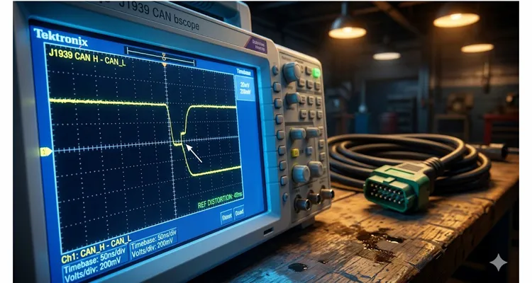
What finally exposed it was a differential probe attached to the transmission ECU, triggered on the recessive‑to‑dominant edge of a specific message ID. At 50 ns/div, the recessive level displayed an unmistakable stair‑step—a tiny voltage perturbation arriving 35 to 40 nanoseconds after the transition. That was the reflection from the 1.8‑meter stub flying back to the node.
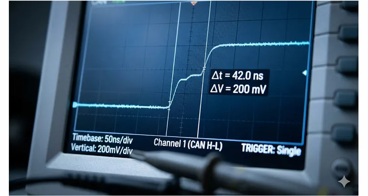
The glitch measured only 200 mV peak‑to‑peak. But at the exact instant the far‑end ECU sampled, those 200 mV pushed its differential voltage beneath the receiver threshold. One node decoded dominant. The other decoded recessive.
Bit error. TEC +8. Repeat.
How We Fixed It—And How You Can Verify the Fix
The root cause was physical, so the remedy had to be physical as well.
Step 1: Measure the actual stub length. Never trust an as‑built drawing. We peeled back the loom and used a steel tape. J1939‑11 mandates a 1‑meter maximum stub length at 250 kbps. If yours is longer, you’re operating outside the design envelope. J1939‑15 does permit 3 meters under specific CAN transceiver conditions, but do not assume you have those parts unless you’ve verified them yourself.
Once you’ve confirmed the stub length, it’s also worth running a quick J1939 voltage drop field test to rule out any other physical layer gremlins lurking in the harness.
Step 2: Shorten the stub or relocate the termination. In our case, we moved the connector closer to the backbone and trimmed the stub to 0.6 meters. That shrank the round‑trip reflection time to roughly 6 ns—well below the threshold that could disturb bit sampling.
Step 3: Validate with an oscilloscope. With the stub shortened, we triggered on the same recessive‑to‑dominant edge. The 35–40 ns reflection was gone. The recessive level settled cleanly within 10 ns of the transition.
Step 4: Monitor the error counters over time. After the change, the transmission ECU‘s TEC remained between 0 and 5 throughout a 24‑hour stress test. Zero bus‑off events. Zero error frames.
Step 5: For future designs, evaluate CAN SIC transceivers. CAN SIC (Signal Improvement Capability) transceivers actively drive the recessive level with a 100 Ω source impedance for roughly 530 ns, effectively smothering reflections before they can ring. If your topology forces longer stubs, CAN SIC transceivers can buy you valuable margin. But they are not a substitute for disciplined layout and stub length control.
Five Mistakes That Create This Problem (And One of Them Is Yours)
Mistake 1: Assuming “About a Meter” Is Close Enough
It isn’t. J1939‑11‘s 1‑meter limit comes directly from signal integrity math. Exceed it, and you’re wagering your margin. At 1.8 meters, our customer was nearly double the maximum—and the bit errors proved it.
Mistake 2: The 60‑Ohm Lie
Our customer’s bus read 60.3 Ω with the power off. Textbook perfect—for DC. But termination is fundamentally an AC problem. That multimeter reading says nothing about how a 1.8‑meter stub behaves like an open circuit at the reflection frequency. If you’re using a Fluke to chase CAN reflections, you’re solving the wrong dimension.
Mistake 3: Copying Bit Timing Registers Without Context
The 87.5% sampling point isn’t arbitrary. It’s the sweet spot balancing propagation delay tolerance against oscillator drift. Shift it earlier and you gain propagation margin but lose oscillator headroom. Shift it later and you risk sampling during residual ringing. If you copy bit timing registers from another system—with a different bus length or crystal accuracy—you may be living right on the edge of the timing envelope.
Mistake 4: Using Cable With the Wrong Impedance
CAN expects 120 Ω characteristic impedance. Drop in 100 Ω Ethernet cable or generic twisted pair, and you’ve altered the reflection coefficient at every junction. More reflections, longer settling times, and more unexplained bus‑off events. For the full technical breakdown of what goes into a proper J1939 cable, refer to our J1939 cable specification guide on shield, impedance, and jacket failure. And if you need a quick reference for proper pinout, here’s the J1939 wiring diagram for CAN High and CAN Low.
Mistake 5: Forgetting That Bit Rate and Stub Length Are Married
At 250 kbps, the 1‑meter stub limit is firm. At 500 kbps, you get half the bit time—and your permissible stub length shrinks accordingly. At 125 kbps, you can stretch longer. The relationship is predictable: higher speed leaves less time for reflections to die.
How to Know You Actually Fixed It
Once you’ve shortened the stub or corrected the J1939 topology, run these validation steps:
Error Counter Monitoring
Most J1939 stacks expose TEC and REC. After a proper fix, both should remain below 10 during normal operation. A single‑digit spike is normal—one noise event adds 8, and it takes eight good frames to erase it. Sustained readings above 50 signal an ongoing physical layer issue.
Oscilloscope Validation
Trigger on a recessive‑to‑dominant edge and zoom to 20–50 ns/div. The recessive level should flatten within 15–20 ns. Any ringing beyond 30 ns means reflections are still active on the CAN bus.
Bus Load and Error Frame Rate
A healthy J1939 network at 250 kbps should keep its error frame rate under 0.1% of total traffic. If your protocol analyzer reports more than 1% error frames after the repair, there’s more work to do.
Extended Stress Test
Push the network to maximum expected traffic for at least 24 hours. Log every bus‑off event. After a genuine fix, the count should be zero.
Related Products That Prevent This Before It Starts
If you’re building or maintaining J1939 networks, the physical layer components you choose determine whether you’ll ever have to chase a 42‑nanosecond reflection in the first place.
We manufacture J1939‑compliant cable assemblies with integrated 120 Ω termination resistors that meet SAE J1939‑11 and J1939‑15 specifications. Every assembly undergoes 100% testing for continuity, impedance matching, and signal integrity before it leaves our facility.
We also supply fully custom cable configurations. You define the backbone length, stub lengths, connector types, and termination locations. We build to your exact topology and verify every dimension against your drawing. That erases the “about a meter” problem completely—because you receive a harness where every centimeter is documented and confirmed.
All our J1939 products are produced under IATF 16949 and ISO 9001 quality systems, with full RoHS and REACH compliance. Each assembly passes four inspection stages before shipping. It’s not flashy work. But it’s the difference between a harness that performs and one that silently manufactures 42‑nanosecond nightmares.
If you’re managing a fleet, the cost of chasing these phantom faults adds up fast. Try our diagnostic downtime cost calculator to see exactly what intermittent bus‑off events are costing your operation.
Frequently Asked Questions
Q1: What’s the actual maximum stub length for J1939 at 250 kbps?
SAE J1939‑11 caps it at 1 meter. J1939‑15 allows up to 3 meters under specific CAN transceiver conditions, but this configuration is less common. If you’re unsure which standard governs your system, default to 1 meter.
Q2: How do I calculate my sampling point without special software?
Most CAN controllers make the bit timing registers accessible. The formula is: Sampling Point (%) = (Sync_Seg + Prop_Seg + Phase_Seg1) / (Sync_Seg + Prop_Seg + Phase_Seg1 + Phase_Seg2). Each segment is expressed in time quanta. Divide and multiply by 100.
Q3: Can a logic analyzer show reflection problems?
No. Logic analyzers display the interpreted bit value after the CAN transceiver has already decided dominant or recessive. They cannot reveal the analog waveform anomalies that trigger bit errors. You need an oscilloscope with differential probes.
Q4: Why does adding more nodes make the problem worse?
Every ECU adds capacitance to the bus. Increased capacitance slows edge rates and stretches settling times. The margin between signal stabilization and the sampling point gets compressed, making the entire J1939 network more vulnerable to reflections.
Q5: Is this only a J1939 problem, or does it affect all CAN buses?
The underlying physics applies to every CAN bus. However, J1939‘s fixed 250 kbps data rate and relatively long permissible bus lengths make it especially sensitive. Higher‑speed CAN networks have tighter bit times and even stricter stub constraints.
Q6: How do I know if my error counters are climbing from reflections versus something else?
Reflection‑induced errors usually appear as bit errors and form errors during arbitration and data phases. They tend to be traffic‑dependent—worse when particular nodes are transmitting. CRC errors and ACK errors, by contrast, more often point to protocol or software issues.
Q7: Can I fix long stubs by adjusting the sampling point?
You can recover some margin by moving the sampling point earlier—for instance, to 80% instead of 87.5%. This buys extra settling time for the bus. The trade‑off is reduced oscillator drift tolerance. It’s a temporary patch, not a remedy for gross stub length violations.
Q8: What tools do I actually need to diagnose this properly?
At minimum: an oscilloscope with 100 MHz bandwidth and differential probes. But after inspecting dozens of customer harnesses, we’ve learned the first tool should be a tape measure. Every harness we build undergoes a physical topology check against the approved drawing—backbone length, stub length, connector placement. It’s low‑tech, but it catches the “about a meter” assumption before it becomes a bus‑off. After that, yes—the scope confirms the fix.
Q9: Are CAN SIC transceivers a drop-in replacement?
They’re pin‑compatible with standard CAN transceivers in most cases, but always verify the specific part number. CAN SIC transceivers actively drive the recessive level for roughly 530 ns, neutralizing reflections from unterminated stubs. They’re an excellent choice for new designs where longer stubs are unavoidable, but they don’t excuse sloppy physical layout.
Q10: Does cable quality actually matter for J1939?
Absolutely—more than many engineers realize. Capacitance, twist rate, and shield coverage all influence signal integrity. Cable with true 120 Ω impedance and low capacitance generates fewer reflections and achieves faster settling. J1939 mandates twisted shielded pair for exactly these reasons.
A Problem That Should Not Exist—But Always Does
The 42‑nanosecond reflection that dropped our customer’s J1939 bus wasn’t some freak anomaly. It was the fully predictable consequence of operating beyond the physical layer envelope. The J1939 standard was written precisely to prevent this failure mode—provided you stay inside the guardrails.
If you’re battling mysterious, intermittent bus‑off events, reach for a tape measure first. Measure your stubs. Then put a scope on the differential pair and study what happens 20 to 50 nanoseconds after the bit edge. That tiny window will reveal more than a month of application‑layer debugging ever could.
Need help with J1939 physical layer design or troubleshooting?
We offer engineering support for J1939 network design, including bus topology review, stub length validation, and custom cable harness solutions. All our products are manufactured under IATF 16949 and ISO 9001 certified processes, with full RoHS and REACH compliance.
📱 Chat with us on WhatsApp for immediate engineering support
📧 Send us a message via our Contact Page for OEM customization inquiries, custom cable specifications, or technical consultation
We specialize in custom J1939 cable assemblies—you specify the backbone length, stub configuration, connector types, and termination requirements. We build and test to your exact specifications.
