

Last month, a repair shop nearly ordered a replacement ECU for a 2002 Mercedes Sprinter after their scanner couldn’t communicate with the ABS module. The tool was fine, the OBD2 port had power, but the data stream was silent. The culprit wasn’t the vehicle or the scanner—it was the diagnostic cable’s inability to speak the specific, legacy language required by that model’s body control module. In our two decades of supplying OEM test equipment interfaces, we’ve found that over 25% of “intermittent comms” or “no communication” failures stem from this exact physical-layer mismatch between a generic cable and a vehicle’s specific protocol.
This isn’t about generic P-codes. It’s about the precise electrical and digital handshake between your diagnostic cable and the ECU. Getting it wrong leads to misdiagnosis, wasted hours, and unnecessary parts swaps.
The Problem: The “Universal” Connector That Wasn’t
The scenario is specific and costly. A fleet manager or technician encounters an early-2000s European import or a particular Asian model. The OBD2 port is present, the scan tool is a reputable brand, but communication is partial or fails entirely—connecting to the engine but not the airbag module, or reading only generic powertrain codes.
This isn’t a tool failure. It’s a fundamental mismatch in communication strategy. While the SAE J1962 connector (the standard OBD2 plug) was mandated, the languages spoken through its pins were not. The vehicle is speaking one diagnostic protocol; your interface is attempting another.
The Root Cause: An Era of Competing Diagnostic Languages
The 1996 OBD2 mandate in the US standardized the 16-pin DLC (Data Link Connector) as the physical interface. However, the regulations specified what had to be monitored (emissions-related systems), not how to communicate the data. Manufacturers leveraged existing, cost-effective in-vehicle network systems, leading to a fragmented landscape of legacy OBD2 protocols.
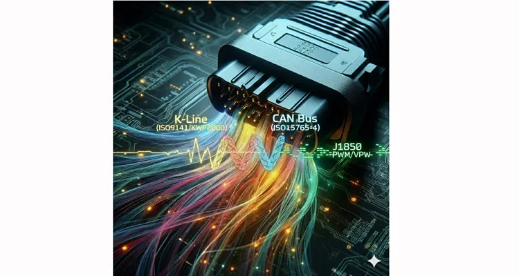
The challenge centers on three key systems:
ISO 9141-2 & ISO 14230-4 (KWP2000)
Often called “K-line” protocols. Think of these not as a robust network, but as a sensitive, single-wire analog conversation. The K-line is a bidirectional serial path where signal voltage levels and timing are everything—a 0.5V deviation can break the handshake. It was the go-to for most pre-2004 European (VW, BMW, Mercedes) and many Asian vehicles (Toyota, Nissan). KWP2000 sharpens this conversation with faster timing and defined “keywords.”
SAE J1850 PWM/VPW
The primary North American legacy standard uses a different “accent” entirely: Pulse Width Modulation (PWM, primarily Ford) and Variable Pulse Width (VPW, primarily GM/Chrysler). It runs on different pins at different speeds. A cable built only for CAN is deaf to this protocol.
The CAN Mandate (ISO 15765-4)
Starting around 2004, CAN diagnostic protocols (using pins 6 and 14) became mandatory. The transition created “hybrid” vehicles: CAN for engine data, but the older K-line retained for body modules like airbags (SRS). This demands a scan tool—and its cable—capable of switching electrical languages on the fly.
The core issue is electrical adaptation. Your diagnostic interface must match the signal type. A cheap, passive OBD2 splitter cable can fatally load these sensitive, legacy signal lines.
Step-by-Step Protocol Identification and Communication Guide
Diagnose the communication protocol as you would an engine fault: methodically.
-
Identify the Vehicle and Year. This is your primary clue.
- 1996-2003/4: High probability of ISO 9141/KWP2000 or J1850.
- 2004-2008: Likely a hybrid mix (CAN for engine, legacy K-line for other modules).
-
Perform a Visual and Voltage Check. With ignition ON (engine OFF), use a digital multimeter on the OBD2 connector pins.
- Verify Battery voltage (~12V) on Pin 16 and a solid ground on Pin 4. No power? You have a broader electrical issue—see our dedicated guide on OBD2 port not communicating.
- Probe Pin 7 (the K-line). You should observe a voltage fluctuating between 8-12V.
- Probe Pins 2 (J1850+) and/or 10 (J1850-) for PWM/VPW signal activity.
- Check Pins 6 (CAN-H) and 14 (CAN-L). They should each read approximately 2.5V at rest (differential voltage of 0V).
- Force a Protocol in Your Scan Tool. Disable auto-detect. Manually select “ISO 9141-2” or “KWP2000” for the target vehicle. A successful connection confirms the protocol.
- Verify with a Known-Good, Direct Interface. If communication is unstable, the fault may lie in the cable or adapter’s ability to handle the legacy protocol’s electrical characteristics. Test with a simple, high-quality direct cable—bypass any splitters or extensions. Our systematic guide on fixing intermittent OBD-II communication delves deeper into this stability challenge.
5 Costly Misconceptions That Break Legacy Protocol Communication
1. Treating the Diagnostic Bus as a Simple Power Tap
Plugging a passive (“dumb”) splitter into a legacy single-wire bus (K-line or J1850) is electrically analogous to adding an unmanaged entrance to a narrow, single-lane road. Signal reflections and increased capacitive load distort the waveform. We once simulated this for a client: a passive splitter degraded signal rise time by over 40%, causing random communication failures in a critical test fixture. The solution isn’t a “better splitter,” but an active interface with proper bus management—a design principle fundamental to our embedded solutions for telematics integrators.
2. Assuming “Universal” Cable Means Fully Pinned
Many low-cost, mass-produced “universal” OBD2 cables wire only the modern CAN pins (6/14), power (16), and ground (4/5). They completely omit the critical Pin 7 (K-line) and Pins 2/10 (J1850), rendering them physically incapable of communicating with pre-CAN vehicles. A true professional-grade universal cable has all 16 pins populated and connected.
3. Overlooking the Analog Nature of “Digital” Handshakes
Legacy protocols like KWP2000 are fundamentally analog-sensitive. A slightly low system voltage (<10.5V), excessive resistance from a long or poor-quality cable, or a high-impedance ground can prevent the precise voltage-based handshake. This is why our assembly specifications mandate precise crimp height standards and high-purity copper conductors—not as a vague quality promise, but as a non-negotiable electrical requirement, a topic explored in our reliability premium cost breakdown.
4. Ignoring Protocol-Specific Initialization Sequences
KWP2000 uses distinct 5-baud address byte wake-up patterns. An incorrect sequence sent by a poorly configured J2534 API or tool interface will simply be ignored by the ECU, resulting in a silent bus.
5. Underestimating EMI on a Single-Wire Signal Path
The K-line is a single-wire serial signal, making it an excellent antenna for electromagnetic interference (EMI). In a typical repair bay, an unshielded diagnostic cable routed near ignition coils or alternator wiring can drown the delicate signal in electrical noise. This is why our approach to shielding is defined by measurable parameters, not marketing. We specify minimum copper braid density (≥95% coverage), enforce 360-degree grounding to the connector shell, and validate these under our IATF 16949 certified process. The financial logic of this rigor is detailed in our shielded vs unshielded cable TCO analysis.For a systematic field guide on diagnosing and mitigating EMI in the harshest environments—including performing the definitive “Pull Test,” auditing ground integrity, and specifying cables with industrial-grade shielding—refer to our dedicated guide: Shielding Your Diagnostics: How to Prevent EMI from Destroying CAN Bus Signals in Noisy Environments.”
How to Confirm Legacy OBD2 Protocols Communication
True diagnostic success is defined by stability and depth of access, not just a connection.
Stable Legacy OBD2 Protocols Data Stream
No random dropouts or checksum errors during extended live data streaming of multiple PIDs.
Multi-Module Access
Ability to query not just the Engine (ECU), but also Transmission (TCM), Airbag (SRS), ABS, etc., as the vehicle and protocol allow.
Successful Code Clearance
Diagnostic trouble codes (DTCs) clear and remain cleared (assuming the underlying fault is resolved).
Verified Bi-Directional Control
Successful actuation of components like a fuel pump, ABS solenoid, or evaporative purge valve, confirming full read/write protocol functionality.
Repeatability Under Physical Stress
The connection survives a deliberate “wiggle test” at the connector. This physical reliability is what our 4-step quality inspection and climate-controlled storage are designed to guarantee, preventing the infamous failures we’ve documented in our 3cm fracture zone analysis.
The Right Cable for the Right Protocol: It’s an Interface Game
Cable selection is dictated by application, not a quest for a nonexistent “one-size-fits-all” solution.
For Legacy Vehicle Diagnostics (pre-2008)
Insist on a cable that is fully pinned (all 16 pins connected) and explicitly specifies support for ISO 9141-2, KWP2000, and SAE J1850.
For Modern, CAN-Centric Fleets
A robust, shielded cable focusing on signal integrity for pins 6/14 is paramount, but having the legacy pins present provides valuable backwards compatibility. Explore our application-specific range for heavy-duty truck applications.
For Permanent Installed Devices (Telematics, ELD)
An active OBD2 Y-cable or port saver with built-in protocol isolation is non-negotiable. It prevents the permanently installed device from interfering with a technician’s scan tool, avoiding costly diagnostic downtime.
Our product philosophy is an extension of this guide: reliability is a system engineered from the component level. Whether it’s a custom cable assembly for an OEM validation rig or a ruggedized J1939 cable for agricultural machinery that must also handle a tractor’s legacy K-line, the design originates from the electrical requirements of the protocol. Every cable that leaves our facility is 100% tested for continuity, correct pinout, and—critically—protocol-specific signal integrity. This rigor is embedded in our IATF 16949 pre-production checkup discipline.
FAQ: Manufacturer-Specific OBD2 Protocols
Q1: My 2005 car has a CAN bus. Why does my tool need KWP2000 support?
A: Many vehicles from this transition era used a hybrid architecture. While the engine (ECU) communicated via mandatory CAN, other control modules (like airbags, immobilizers) often remained on the older, cheaper K-line bus. To achieve full vehicle diagnostics, your interface must support both protocols.
Q2: What’s the practical difference between ISO 9141-2 and KWP2000?
A: Think of ISO 9141-2 as the foundational standard—slower (10.4 kbps), with a simpler initialization. KWP2000 (Keyword Protocol 2000) is its evolution, offering faster data transfer (initially up to 10.4 kbps, with faster variants later), greater robustness, and standardized “keywords” for secure access to protected functions. Physically, they often share the same K-line, so a quality interface should handle both.
Q3: Can selecting the wrong protocol physically damage my car’s ECU?
A: With modern scan tools, it is highly unlikely to cause permanent physical damage. However, it can cause a module to enter a sleep mode or require a key cycle/reset to recover. The primary risks are wasted diagnostic time and the potential for misdiagnosis.
Q4: If J2534 is a software standard, is the cable itself still critical?
A: Absolutely. During ECU flashing or module programming, a J2534 device performs sustained, high-intensity communication for minutes. A cable with elevated resistance or poor shielding can introduce voltage drops or bit errors during this critical period, leading to flash failure—a “bricked” module. The cost of failure isn’t the cable, but days of vehicle downtime, a costly ECU replacement, and operational disruption.
Q5: Why does my aftermarket GPS or infotainment unit work, but my professional scan tool fails?
A: The aftermarket device typically only listens to basic, broadcast CAN data (like vehicle speed, RPM) on pins 6/14. Your professional scan tool is attempting to initiate a complex, bidirectional diagnostic session on a legacy protocol (like K-line on Pin 7), which is a fundamentally different and more demanding electrical conversation.
Q6: How do heavy-duty protocols like J1708 and J1939 relate to this?
A: They are separate, high-level vehicle network protocols used primarily in trucks, buses, and industrial equipment for real-time data exchange, not just diagnostics. However, diagnostic requests on a J1939 network are encapsulated within standard CAN data frames. Understanding the J1939 connector pinout is crucial for heavy-duty work. The technological shift from J1708 to J1939 parallels the passenger car world’s move from legacy single-wire systems to robust, dual-wire CAN. For relevant cables, see our diesel application category.
Q7: My cable works on my 2006 Honda but not my 2006 BMW. Why?
A: This is a classic indicator. Honda phased in CAN earlier for most modules. BMW, like many European manufacturers, retained K-line for body modules well into the mid-2000s. Your cable likely lacks the physical connection to Pin 7 (K-line), which the BMW requires.
Q8: Is there a single, truly universal OBD2 cable that works on everything?
A: Electrically, the closest you can get is a high-quality, fully pinned (all 16 pins connected), shielded cable paired with a robust, intelligent interface adapter that can handle the signal translation for all protocols. There’s no magical passive cable. The goal is “engineered for the application,” which sometimes means a specific cable for a specific era or vehicle type. This rationale—investing in correctness over cheap universality—is the core of our reliability premium cost breakdown.
This systematic, protocol-first approach is underpinned by our commitment to certified management systems, including ISO 14001 environmental management and a rigorous internal audit process aligned with industry standards.
Navigating this protocol landscape requires more than information—it requires the correct physical interface. When the success of your diagnostics, fleet compliance, or OEM testing hinges on flawless communication, the cable is the most critical, and most frequently underestimated, component in the chain.
If you are specifying cables for a mixed fleet, designing a test bench for multiple vehicle platforms, or simply frustrated by unreliable “universal” adapters, let’s discuss the engineering specifics. We can analyze your exact protocol mix and environmental challenges (vibration, temperature, EMI) to provide a custom OBD2 cable assembly that delivers reliability from the first connection onward.
Discuss your protocol and application challenges with our engineering team.
Contact us for a free, no-obligation engineering consultation. Or, for a quicker conversation, reach out directly on WhatsApp.
(For further reading: Understand the broader network context with our J1708 vs J1939 Protocol Comparison Guide , or see how protocol stability is ensured in harsh environments in our piece on J1939 Cables for Agricultural Machinery . For a framework on vetting suppliers for such complex needs, review our J1939 supplier audit framework .)
