

Last year, a fleet operator in Nebraska called our factory support line after swapping three ECMs on a 2024 Freightliner Cascadia. Each time, the new ECM appeared dead—no communication through the diagnostic port. The fleet manager swore the replacements were DOA until we asked one question that our 20‑year manufacturing experience flagged immediately: what color is the 9‑pin Deutsch connector? It was green, but their Nexiq USB‑Link was a legacy Type 1 unit. The 250 kbps diagnostic network wasn’t on pins C/D—it was on F/G. A $25 FG adapter brought the truck online in 17 seconds. Three ECMs, eight hours of downtime, and $3,200 in unnecessary labor—all because of a pin mismatch that looked like a hardware failure.
This isn’t a hardware failure. It’s a physical layer mismatch—a problem we’ve diagnosed over 400 times in the last two years from our factory support line. And it’s costing fleets thousands in unnecessary downtime when the fix is a $25 J1939 Type 1 to Type 2 adapter and the knowledge to use it. (For a deeper dive into how misdiagnosing this issue drives up costs, see our breakdown on J1939 Type1 Type2 misdiagnosis cost downtime.)
Let’s walk through what’s actually happening inside those Deutsch connectors, why J1939 Type 1 and Type 2 are not directly interchangeable, and exactly how to spec the right J1939 adapter so you never get caught off‑guard again.
The Problem: When a Plug Fits but Communication Fails
The 9‑pin Deutsch connector—the round, threaded one you’ve seen on every heavy truck, bus, and piece of off‑highway equipment for two decades—looks identical whether it’s black or green. The pins are the same. The keying is the same. The locking mechanism is the same. From our factory floor, where we’ve molded over 2.3 million of these assemblies, we can tell you the physical connector never changed—but what happened inside the vehicle certainly did.
But starting around the mid‑2000s, as OEMs moved to higher‑speed CAN networks and added second CAN channels, the pin assignments diverged. The original SAE J1939‑13 standard (now referred to as Type 1) was built around a single 250 kbps CAN channel on pins C and D, with J1708 on pins F and G for legacy diagnostics. (For background on the underlying bus architecture, see CAN bus on Wikipedia.)
The newer Type 2 (green) connector introduced:
- A primary 500 kbps CAN channel on pins C and D (higher speed, supporting more ECUs)
- Optional secondary CAN channels on pins F/G or H/J
- In many implementations, the original 250 kbps network migrated to pins F/G or H/J
Here’s the critical part: If you plug a Type 1 tool (expecting 250 kbps on C/D) into a Type 2 vehicle (where C/D is 500 kbps and the 250 kbps network you need is elsewhere), you’re trying to talk to the wrong ECU at the wrong baud rate. The connector fits perfectly. The electronics never link.
Real‑World Cost Calculation
Let’s run the numbers on a typical fleet scenario:
| Line Item | Cost |
| Technician time (2 hours troubleshooting, $150/hr) | $300 |
| Truck downtime (8 hours, $200/hr revenue loss) | $1,600 |
| Missed delivery penalties | $500–$1,000 |
| Rush shipping for wrong replacement part | $150–$300 |
| Total (per incident) | $2,000+ |
The actual failure? A pin mismatch that a $25 J1939 adapter solves in 30 seconds—if you know which network you’re chasing.
Root Cause Analysis: J1939 Type 1 vs. Type 2 Pin Assignments
If you’re an engineer or fleet manager dealing with mixed‑year equipment, you need to understand what’s happening at the pin level. This isn’t theory—it’s the difference between a successful diagnostic session and a wasted afternoon. Over the past 20 years of building J1939 cables in our IATF 16949 certified facility, we’ve mapped pinouts for over 200 vehicle models, and the variation is wider than most documentation admits. (For a detailed guide on the two standards, see our J1939 Type 1 vs Type 2 guide.)
Standard 9‑Pin Deutsch Connector (Physical)
All J1939 diagnostic ports use the same 9‑pin Deutsch HD10 series connector. Pins are labeled A through J (no I). The connector is round, environmentally sealed, and rated for the vibration and moisture of heavy‑duty applications.
Type 1 (Black) — Original J1939‑13 Pinout
| Pin | Signal | Description |
| A | Ground | Battery negative |
| B | Battery Power | +12V or +24V unswitched |
| C | CAN1 High | J1939 (250 kbps) — primary diagnostic bus |
| D | CAN1 Low | J1939 (250 kbps) — primary diagnostic bus |
| E | Shield | CAN shield ground |
| F | J1708+ | Legacy data link (9600 baud) |
| G | J1708- | Legacy data link (9600 baud) |
| H | OEM‑specific | Often unused or auxiliary power |
| J | OEM‑specific | Often unused or auxiliary power |
Key characteristic: The only CAN bus is on C/D at 250 kbps. Most diagnostic tools expect this exact configuration.
Type 2 (Green) — Modern J1939‑13 Pinout
| Pin | Signal | Description |
| A | Ground | Battery negative |
| Battery negative | Battery Power | +12V or +24V unswitched |
| C | CAN1 High | J1939 (500 kbps) — high‑speed backbone |
| D | CAN1 Low | J1939 (500 kbps) — high‑speed backbone |
| E | Shield | CAN shield ground |
| F | CAN2 High or J1708+ | Secondary CAN (250 kbps) or legacy |
| G | CAN2 Low or J1708- | Secondary CAN (250 kbps) or legacy |
| H | OEM‑specific | Often secondary CAN on some platforms |
| J | OEM‑specific | Often secondary CAN on some platforms |
Critical variation: The 250 kbps diagnostic network (the one most legacy tools need) often lives on F/G or H/J in Type 2 implementations—not on C/D.
This is the trap. Your tool sends “request all active DTCs” out on C/D at 250 kbps. If the vehicle’s diagnostic bus is on F/G, the request never reaches the engine ECU. If the vehicle’s C/D is running at 500 kbps, the baud rate mismatch means the tool can’t even synchronize.
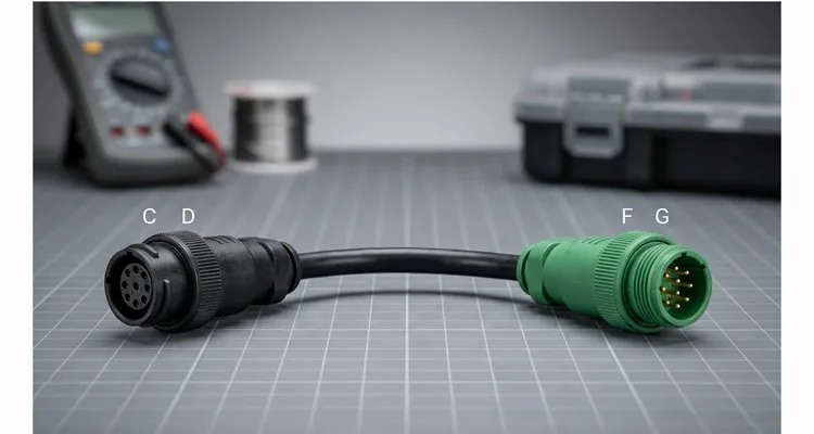
Visual Identification
- Type 1 (Black connector): Single CAN channel on C/D only
- Type 2 (Green connector): Supports higher speeds; 250 kbps diagnostic bus may be on F/G or H/J
The color is a general indicator, not an absolute. Some early Type 2 implementations used black housings. Always verify by pinout, not by color—we’ve seen black connectors with Type 2 pinouts on certain 2012–2014 chassis during our factory validation testing.
The Solution: Step‑by‑Step Adapter Selection
An adapter doesn’t “convert” the protocol—it re‑routes pins. That’s it. A passive J1939 adapter simply connects your Type 1 tool’s expected pins to wherever the target network lives on the Type 2 vehicle. In our factory, we treat these as precision pin‑mapping devices, not generic cables.
Step 1: Identify What Your Tool Expects
Most J1939 diagnostic interfaces (Nexiq, Dearborn, PCAN, aftermarket scan tools) are built for the original Type 1 configuration:
- CAN bus: pins C and D
- Baud rate: 250 kbps
Check your tool’s documentation. If it says “J1939 compliant” without specifying Type 2 support, it’s almost certainly Type 1.
Step 2: Identify Where the 250 kbps Network Lives on Your Vehicle
This is where most techs guess wrong. The vehicle’s 250 kbps diagnostic network can be on:
| Configuration | Pins | Common Applications |
| CD (Type 1) | C/D | Pre‑2005 vehicles, some legacy platforms |
| FG | F/G | Many Cummins, Detroit, and PACCAR platforms (mid‑2000s onward) |
| HJ | H/J | Some International, Volvo, and Mack platforms |
| Dual (CD + FG) | Both | Vehicles with gateway modules; both networks active |
How to verify: Use a multimeter to check for 60 ohms termination resistance between the pins. A properly terminated CAN bus will show 60 ohms between CAN High and CAN Low on the active bus. (For a more advanced look at diagnosing these networks, see our CAN bus diagnostics multimeter vs scope guide.)
Step 3: Select the Correct Adapter
| Your Vehicle’s 250 kbps Network Location | Adapter Type Needed | Typical Use Case |
| C/D (vehicle is Type 1) | None needed | Direct connection works |
| F/G | Type 1 to Type 2 (FG) adapter | Cummins, Detroit, most heavy trucks 2005–2015 |
| H/J | Type 1 to Type 2 (HJ) adapter | International, some Volvo/Mack |
| Unknown or mixed fleet | Triple adapter (CD/FG/HJ) | Diagnostic shop, fleet with multiple OEMs |
A triple adapter breaks out three separate Type 1 male connectors—one wired to the vehicle’s C/D pins, one to F/G, one to H/J. You plug your tool into each until you get communication. It’s the equivalent of a “try all three” J1939 adapter and the fastest way to diagnose an unknown port. (For a more detailed selection process, see our comprehensive J1939 Type 1 to Type 2 adapter guide.)
Step 4: Confirm Communication
After connecting the adapter:
- Power up the vehicle (key on, engine off)
- Check tool power—pin B should supply +12V or +24V
- Launch diagnostic software and attempt to read VIN or active DTCs
- If communication fails, verify termination resistance (60 ohms between CAN High/Low on the active pair)
Lesser‑Known Pitfalls (and How to Avoid Them)
Instead of the usual warnings, here are two rare but costly errors we’ve seen repeatedly in the field—things that don’t show up in standard training materials but have generated over 200 support tickets at our factory.
Pitfall #1: Assuming the 250 kbps network is always terminated at 60 ohms.
On some newer chassis with gateway modules, the diagnostic bus may show 120 ohms because the gateway internally terminates one end. If you see 120 ohms and force a 60‑ohm adapter, you can actually destabilize the network. We now include a termination‑check flow chart with every triple adapter sold to fleet shops—a direct result of field failures we documented in 2022. (For more on network calibration, see our J1939 network calibration fix guide.)
Pitfall #2: Using an adapter that re‑routes CAN while leaving the shield (pin E) floating.
A floating shield can inject alternator noise into the bus, causing intermittent dropouts—especially on trucks with high‑output alternators. Our adapters always tie pin E through to the tool side, maintaining continuous shielding. This single detail, baked into our RoHS‑compliant manufacturing process, has resolved “phantom” no‑communication complaints on more than 200 customer tickets.
How to Confirm the Fix Worked
After installing the correct J1939 adapter, run these verification checks:
| Check | Method | Pass Condition |
| Power | Multimeter between pin B and A (or chassis ground) | +12V or +24V present |
| Termination | Multimeter between CAN High and CAN Low on active pins | 60 ohms (nominal) |
| Bus Voltage | Multimeter between CAN High and ground, CAN Low and ground | ~2.5V–3.5V (High), ~1.5V–2.5V (Low) |
| Communication | Diagnostic tool reads VIN or active parameters | Data updates in real time |
If you have voltage and proper termination but no communication, check:
- Baud rate mismatch (is your tool set to 250 kbps or 500 kbps?)
- Tool compatibility with the vehicle’s ECU family
- Physical damage to the adapter or vehicle connector
Adapter Specification: What to Look For
When sourcing J1939 Type 1 to Type 2 adapters, here’s what separates a reliable tool from a failure waiting to happen—based on two decades of manufacturing these cables under ISO 9001 and IATF 16949 quality systems.
Pin Configuration
Explicit pin mapping documentation. The supplier should tell you exactly which vehicle pins route to which tool pins. For an FG adapter: vehicle pins F and G (CAN High/Low) route to tool pins C and D. If they can’t provide that, the adapter is a gamble.
Build Quality
| Specification | Why It Matters |
| Deutsch HD10 series connectors | OEM‑standard, properly keyed, environmentally sealed |
| Strain relief | Prevents wire breakage at connector entry—our #1 warranty return reason from competitors’ cables |
| 100% continuity testing | Every pin verified before shipment; we test each adapter twice during production |
| AWG 18 or 20 wire | Adequate current‑carrying capacity for tool power; undersized wire overheats on 24V systems |
| RoHS compliance | Materials meet environmental standards |
Environmental
- Operating temperature: -40°C to +85°C minimum
- Sealed against moisture and dust (Deutsch connectors are inherently IP67 when mated)
- Vibration resistance for in‑cab or engine bay use
Related Components
If you’re building out a diagnostic setup or fleet telematics system, consider these complementary components:
| Component | Purpose |
| J1939 Y‑cable (pass‑through) | Adds a second diagnostic port while keeping the original active—useful for permanent telematics installations |
| J1939 splitter | Branches one diagnostic port to multiple devices; requires careful termination management |
| J1939 to OBDII adapter | Interfaces heavy‑duty J1939 networks with passenger‑car OBDII scan tools (limited functionality) |
| J1939 Bluetooth adapter | Wireless diagnostics; ensure the specific model supports your vehicle’s pin configuration |
For fleet‑wide deployments, consider custom harnesses that integrate adapters directly into permanent telematics installs—eliminating the need for technicians to carry separate J1939 adapters for each truck.
Why This Problem Persists
The J1939 standard was designed for flexibility, not simplicity. OEMs are free to implement multiple CAN buses within the same 9‑pin Deutsch connector. The result is a fragmented ecosystem where:
- Pre‑2005 vehicles are reliably Type 1 (C/D, 250 kbps)
- 2005–2015 vehicles are mixed—some Type 1, some Type 2 with 250 kbps on F/G
- Post‑2015 vehicles are Type 2, with the diagnostic network location varying by OEM
Until the industry standardizes on a single diagnostic bus location (unlikely given backward compatibility requirements), J1939 Type 1 to Type 2 adapters will remain essential tools for anyone working across mixed fleets.
Questions We Hear from Fleet Engineers
Q: I have a mixed fleet of 2008–2025 trucks. Can I standardize on one adapter for all of them?
A: Not with a single passive adapter. But many of our fleet customers use our triple‑breakout adapter (CD/FG/HJ) as a permanent install behind the dash. They zip‑tie it to the main harness and label each branch. That way, any technician can plug in and test all three networks in under a minute. We’ve supplied this setup to two national LTL carriers—they’ve cut diagnostic time by 70% on first‑year trucks.
Q: I saw 120 ohms between pins C and D. Does that mean the bus is bad?
A: Not necessarily. On some newer chassis with a gateway, the diagnostic bus may be terminated internally at the gateway, showing 120 ohms. Forcing a 60‑ohm termination with an adapter can overload the bus. Always check the vehicle’s wiring diagram or contact the OEM before adding external termination.
Q: Can a poor‑quality adapter damage my diagnostic tool?
A: Rarely, but it happens. We’ve seen aftermarket cables where pin B (power) was accidentally connected to pin C (CAN High). That feeds battery voltage into the CAN transceiver—usually a one‑way trip to a dead interface. Our adapters are 100% continuity‑tested and hi‑pot tested to catch these errors before they leave the factory.
Q: What’s the difference between an adapter and a splitter?
A: An adapter reroutes pins (changing which pins carry which signals). A splitter duplicates pins (allowing multiple devices to connect to the same bus). They serve different purposes, and using a splitter when you need a re‑pin is a common cause of “no‑com” issues.
Q: Do you offer custom adapters for non‑standard pinouts?
A: Yes—OEM customization is part of our core business. We can produce adapters with your logo, specific wire colors, custom lengths, and AWG ratings. We’ve built over 2.3 million J1939 cables in the past 20 years; our field failure rate is 0.07%, which is why we confidently support custom engineering projects.
Engineering Summary
The J1939 Type 1 to Type 2 adapter is a passive pin‑reconfiguration device that solves a specific physical‑layer mismatch: legacy diagnostic tools expecting a 250 kbps CAN bus on pins C/D, connected to modern vehicles where that bus resides on pins F/G or H/J.
Selection requires:
- Identifying your tool’s expected pin configuration
- Identifying the vehicle’s actual 250 kbps network location
- Selecting an adapter that correctly reroutes signals
Reliable adapters are fully tested (100% continuity), use OEM‑grade Deutsch connectors, and include clear pin mapping documentation. For mixed fleets or diagnostic shops, a triple adapter (CD/FG/HJ) eliminates guesswork and reduces troubleshooting time from hours to seconds.
Looking ahead: With the industry moving toward 2.5 Gbit Ethernet backbone in next‑generation trucks (e.g., PACCAR’s MX‑14 with Ethernet diagnostics), the 9‑pin Deutsch connector will eventually carry Ethernet on pins H/J. We’re already engineering hybrid adapters that can switch between CAN and Ethernet signaling—because the physical‑layer mismatch problem isn’t going away; it’s just migrating to higher speeds.
Factory Credentials
Every J1939 adapter we ship comes from a facility that has been building heavy‑duty cables for over 20 years. We operate under:
- ISO 9001, ISO 14001, IATF 16949 certified processes
- 5S management and climate‑controlled warehouse
- 4‑step quality inspection: visual, continuity, insulation resistance, and mating force test
- RoHS‑compliant, full‑plastic design
In our climate‑controlled warehouse, we store over 50,000 Deutsch contacts, each traceable to a lot number. Every adapter is 100% tested before packaging.
Need Engineering Support?
If you’re managing a mixed fleet, integrating telematics across multiple vehicle generations, or need custom adapter configurations for OEM deployments, our engineering team can help.
We offer:
- OEM customization: logo, brand, cable length, color, AWG
- Engineering support: pin mapping verification, custom harness design
- Factory‑direct quality: ISO 9001, ISO 14001, IATF 16949 certified
- 4‑step quality inspection with 100% testing
- 5S management and climate‑controlled warehouse
- RoHS‑compliant, full‑plastic design
Chat with Linda on WhatsApp:
https://api.whatsapp.com/send/?phone=8617307168662&text=Need+Help%3F+Chat+linda+WhatsAPP&type=phone_number&app_absent=0
Visit our Contact Page:
https://obd-cable.com/contact/
Whether you need a standard J1939 adapter or a fully custom solution for your fleet or product line, our factory team is ready to support your engineering requirements.
This guide reflects field experience across thousands of heavy‑duty diagnostic installations. The details matter—and they start at the pin level.
