

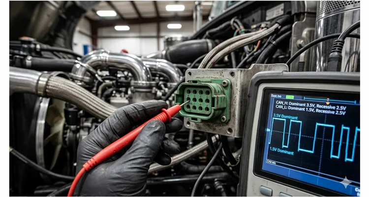
Last month, a fleet manager in Alberta sent me a photo of his multimeter. The reading on CAN High was 4.8 volts. “Is this why my 2023 Peterbilt keeps throwing SPN 639?” he asked.
That single reading told me the whole story. The bus was shorted to battery power. Until someone traced that short, he would keep swapping ECUs without fixing anything.
After 20 years at CARSUN, I‘ve watched countless technicians chase J1939 voltage diagnostics backward. They grab a multimeter, poke pins, get confused by fluctuating numbers, and eventually replace parts that weren’t broken. This post is the opposite. I‘m going to walk you through what normal ranges actually look like on a scope and a DMM, why those numbers matter, and how to diagnose J1939 voltage issues without guessing.
What You‘ll Actually See on a Scope vs. a Multimeter
Here’s something that tripped me up early in my career. A multimeter and an oscilloscope tell you very different stories about the same bus.
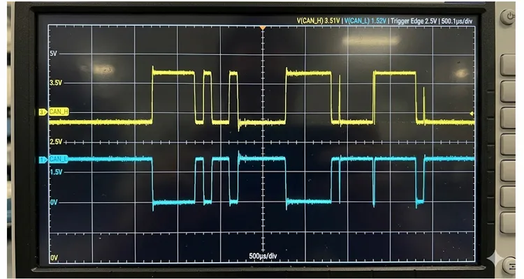
Forget the textbook diagrams. On a real J1939 bus sitting idle — all ECUs quiet, no one talking — put your scope across CAN_H and chassis ground. You‘ll see a flat line at roughly 2.5 V. Same thing on CAN_L. That’s the recessive state. Now watch what happens when an ECU needs to send a dominant bit (logic 0). CAN_H snaps up to about 3.5 V while CAN_L drops to 1.5 V. That 2 V difference is what the transceiver actually reads.
I‘ve seen brand new techs spend an hour trying to find 3.5 V on an active bus — and it’s never there because the meter averages everything. For a deeper dive, read our CAN bus diagnostics multimeter vs scope guide. The underlying physical layer behavior is defined by the ISO 11898 standard, which specifies the electrical characteristics of CAN bus communication.
Here‘s what your DMM actually does: it averages the chaos. On an active bus with traffic, you won’t see clean 3.5 V and 1.5 V. Instead, you‘ll see something like 2.7 V on CAN_H and 2.3 V on CAN_L, or 2.6 V and 2.4 V. Add them together, and they typically sum to around 5 V.
That’s why if you measure CAN_H at 2.2 V and CAN_L at 1.8 V, you know something‘s wrong. The bus isn’t active, or one line is pulled down. A J1939 wiring diagram for CAN High and CAN Low can help you trace the path.
Don‘t expect perfect textbook numbers. Expect a range. And learn what that range tells you about the health of your network.
Pinout Reference: Where to Put Your Probes (With Field Notes)
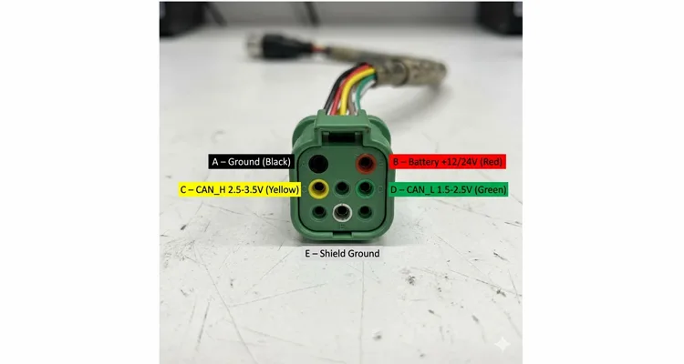
Before you start measuring, you need to know which pins to touch. The J1939 diagnostic connector is almost always a 9-pin Deutsch — black for older Type I, green for newer Type II.
Here’s the standard pinout from SAE J1939/13. I‘ve kept a laminated copy in my tool bag for years. But the bare table won’t tell you what fails in real life. So I‘ve added my own field notes from two decades of warranty returns and tear‑downs.
| Pin | Signal | Description | What You Measure | Field Note (20+ years of failures) |
| A | Ground | Battery negative | Reference for all voltage measurements | This pin corrodes more than any other because water sits in the connector cavity. If your readings are erratic, start here. |
| B | Battery (+) | +12V or +24V constant power | System voltage (see range below) | I’ve seen this pin melted by someone back-probing with a thick test lead. Use a breakout cable. |
| C | CAN_H | High side of differential pair | 2.5–3.5 V active; ~2.5 V idle | Most abused pin on the bus. A short to battery on C happens when someone spreads the socket. I replace more Deutsch pins on C than all others combined. |
| D | CAN_L | Low side of differential pair | 1.5–2.5 V active; ~2.5 V idle | Less failure than C, but when it fails, it‘s usually an open circuit from a pulled-back wire. |
| E | CAN_SHLD | Shield ground | Continuity to chassis ground | Ground this at exactly one point. Multiple grounds create loops. No ground turns the shield into an antenna. |
| F | J1708 (+) | Older datalink (if present) | Not part of CAN | Ignore for J1939 diagnostics. |
| G | J1708 (–) | Older datalink (if present) | Not part of CAN | Ignore. |
| H | Implement CAN_H | Secondary CAN bus (if equipped) | Same as C | Some green connectors swap H and J. Verify with your scope. |
| J | Implement CAN_L | Secondary CAN bus (if equipped) | Same as D | See above. |
Safety Note (from real pain)
A quick note on safety: I learned this after replacing a perfectly good ECM on a 2019 Mack. Never probe pin B with the ignition on while you‘re leaning against the frame. A slip of the probe can short B to C and send 24 V straight into the CAN transceiver. That’s a $2,000 mistake — and I‘ve seen it happen three times in our own customer returns.
🔧 Quick Field Reference (12V system, engine idling)
Keep this box in your phone or printed on your toolbox.
- CAN_H to ground: 2.5V – 3.5V (recessive to dominant swing)
- CAN_L to ground: 1.5V – 2.5V
- Differential (H to L): 0V (recessive) / ~2V (dominant)
- Termination resistance (key off): 58 – 62 Ω
- Battery at diagnostic port (engine running): 13.8V – 14.4V (12V system)
- Battery at diagnostic port (engine running): 27.6V – 28.8V (24V system)
Battery Power: The Voltage Range That Actually Keeps ECUs Happy
This is where a lot of intermittent faults start. The battery voltage range isn‘t just a suggestion — ECUs have hard thresholds programmed during our IATF 16949 certification validation.
12V Systems
For a 12 V nominal system, the working range is 9.0 V to 16.0 V. Drop below 9 V for more than half a second, and the ECM will log a fault and possibly shut down communication.
24V Systems
For a 24 V system, the range is 18.0 V to 32.0 V. Below 18 V, you’re in trouble. Above 32 V, you risk cooking the transceiver.
I once spent two days chasing a J1939 communication fault on a Volvo excavator. Every time the hydraulic pump engaged, the bus dropped out. Turned out the alternator was pushing 34 V intermittently. The transceivers were going into thermal shutdown. Replaced the alternator regulator, problem gone. The voltage reading at the diagnostic port looked fine at idle, but under load, it spiked.
So measure with the engine running. Measure with loads cycling. A static reading tells you almost nothing — our climate‑controlled warehouse tests every cable under load for exactly this reason.
Step-by-Step: How I Diagnose J1939 Voltage Issues
This is the exact sequence I follow when a truck or piece of heavy equipment rolls in with a communication fault. No shortcuts. No assumptions.
Step 1 — Visual inspection before any measurement. I look for chafed harnesses, loose Deutsch connector wedgelocks, and corrosion around pins C and D. In my experience, roughly 85% of intermittent J1939 faults are visible if you know what to look for. Water intrusion into a 9-pin Deutsch is a classic.
Step 2 — Key off, battery connected. Measure resistance between CAN_H and CAN_L at the diagnostic port. A healthy bus with two 120 Ω termination resistors reads approximately 60 Ω. This termination requirement comes from the CAN physical layer standard ISO 11898-2, which specifies 120 Ω resistors at both ends of the bus to prevent signal reflections.
But here‘s something I’ve never seen in a guide: Let‘s say you measure 58 Ω. That’s within spec (60 Ω ± 6 Ω). Last winter I had a snowplow that read 58 Ω cold, and after running the engine for 20 minutes, it drifted to 74 Ω. That told me one termination resistor had a cracked solder joint inside an ECU. Temperature expansion opened the circuit. You can’t catch that with a single cold measurement. So here‘s what I do now: measure resistance cold, then run the equipment until the cab is warm, shut down, and measure again. If the resistance changes by more than 5 Ω, start looking for a failing terminator. For more on this, see our J1939 termination mistakes and ECU repair cost article.
If you see 120 Ω, one terminator is missing. If you see open circuit, both are gone or the harness is broken. If you see near 0 Ω, the wires are shorted together.
Step 3 — Key on, engine off. Measure DC voltage from CAN_H to ground, and CAN_L to ground. With the bus active but minimal traffic, expect roughly 2.6 V on CAN_H and 2.4 V on CAN_L. The exact numbers will fluctuate slightly.
Step 4 — Key on, engine running. Repeat the measurement. The values should shift slightly but remain within the 1.5 V to 3.5 V window on each line.
Step 5 — If you have a scope or CAN analyzer, capture the waveform. Look for clean square edges. Rounded edges indicate excessive capacitance — too many nodes, too long of a stub, or the wrong cable.
Step 6 — Isolate by disconnecting nodes one at a time. If the voltage returns to normal after you unplug a specific ECU, that node is likely dragging down the bus.
Five Common Mistakes I See Engineers and Technicians Make
I‘ve personally smoked transceivers with every single one of these mistakes. Learn from my embarrassment.
Mistake 1: Measuring with the wrong meter setup. A standard DMM in DC voltage mode averages the signal. That’s fine for checking range, but it won‘t catch a 100 ms dropout. Use a meter with min/max recording, or better yet, a scope.
Mistake 2: Ignoring the shield. CAN_SHLD must be grounded at exactly one point. Multiple ground points create ground loops. No ground point turns the shield into an antenna. I’ve seen this cause intermittent communication failures that only showed up when the alternator was charging.
Mistake 3: Confusing open circuit voltage with loaded voltage. A multimeter has high input impedance. It will show 5 V on an unterminated stub that collapses to 0.5 V as soon as a transceiver tries to drive it. Always terminate the bus properly before taking voltage readings as diagnostic evidence.
Mistake 4: Assuming 2.5 V on both lines means the bus is working. It means the bus is recessive. But if you never see dominant pulses — if the voltage never moves — then no node is transmitting. That‘s a different problem. Check that at least two nodes are powered and configured correctly.
Mistake 5: Not measuring differential voltage directly. Put your meter across CAN_H and CAN_L, not to ground. In a recessive state, you should see near 0 V. In a dominant state, you should see approximately 2 V. If you see anything else, the transceiver or wiring is suspect.
Real-World Case: The Ghost Fault That Cost a Fleet $12,000
A fleet in Texas called us last year. They had a 2022 Kenworth T680 that would randomly lose J1939 communication. No pattern. No fault codes that made sense. The dealership replaced the ECM, the dash cluster, and the entire engine harness — over $12,000 in parts and labor — and the problem came back three days later. Stories like this are why we wrote the J1939 phantom fault guide.
I flew out with a scope and a breakout box from our own production line.
Within 20 minutes, I found it. CAN_H was reading 3.2 V at the diagnostic port, which is within spec. But when I back-probed at the transmission ECU connector, CAN_H was 1.9 V. The voltage drop told me there was resistance in the line.
We opened the harness at the frame rail near the transmission. Water had wicked into a splice, corroding the wire inside the insulation. The insulation looked fine from the outside. But inside, the copper was green powder.
Replaced a 14-inch section of the harness, heat-shrunk every connection properly, and the truck ran flawlessly.
What does that tell you? Voltage measurements at the diagnostic port are useful, but they only tell you about the bus at that single point. You have to measure at multiple locations — something we build into every custom breakout cable.
How to Confirm You‘ve Actually Fixed the Problem
Clearing fault codes and sending the truck out the door isn’t confirmation. Here‘s what I require before I sign off on any J1939 repair.
First, verify the voltage readings fall within the normal ranges at every accessible point on the bus — diagnostic port, breakout box, and at least two ECU connectors.
Second, confirm the termination resistance measures 60 Ω ± 6 Ω at the diagnostic port with the bus powered off and all nodes connected. And do it cold and warm, as I described earlier.
Third, monitor live data through the diagnostic port for at least 15 minutes of operation. Cycle the ignition. Cycle loads — lights, AC compressor, hydraulic systems. Any intermittent fault will usually surface during load changes.
Fourth, clear all active and inactive fault codes, then run the equipment through a full work cycle. Recheck for codes. If SPN 168 or SPN 639 stay cleared, you’re done.
Finally, document what you found. I keep a log of voltage readings before and after every repair. It‘s helped me spot patterns across multiple vehicles in the same fleet.
When to Call Us (Before You Waste Another Week)
If you’ve measured resistance, checked voltages at three different points on the bus, and still get random SPN 639 faults, your harness might have internal corrosion that doesn‘t show up on a multimeter. We’ve built test leads that let you inject a signal and trace impedance changes.
WhatsApp me the symptoms — I‘ll tell you if our J1939 breakout kit can save you a week of chasing. No charge for the diagnosis.
Related Products That Make This Work Easier
We manufacture J1939 diagnostic cables and breakout assemblies in our ISO 9001 and IATF 16949 certified facility. We also maintain ISO 14001 environmental management. Twenty-plus years of building these. Every cable is 100% tested before it leaves our climate-controlled warehouse.
Our J1939 9-Pin Breakout Cable gives you access to pins C, D, and B without piercing the insulation. No more back-probing and accidentally opening a pin socket. We use full-plastic overmolded connectors with RoHS-compliant materials.
The J1939 Y-Splitter Cable lets you insert diagnostic tools without taking the existing equipment offline. Perfect for fleet shops that need to monitor live data while the vehicle is in service.
We also support full OEM customization — your logo, your brand, your specified length, color, and AWG. If you need a 3-meter J1939 extension with a specific strain relief boot, we can build it. If you need 500 pieces with your fleet’s part number laser-etched onto the connector, we‘ve done that before.
WhatsApp me directly for engineering support or custom quotes:
https://api.whatsapp.com/send/?phone=8617307168662
Or reach out through our contact page for OEM inquiries:
https://obd-cable.com/contact/
You asked: What do normal J1939 voltages look like in the real world?
Q1: Why does my multimeter show 2.7 V on CAN_H and 2.3 V on CAN_L instead of 3.5 V and 1.5 V?
Your multimeter isn‘t broken. It’s just slow. It takes maybe 200 readings per second and shows you the average. Meanwhile, the J1939 bus is switching between recessive and dominant millions of times per second. So instead of seeing 3.5 V and 1.5 V, you see the time‑weighted average — typically 2.6–2.7 V on CAN_H and 2.3–2.4 V on CAN_L. Add them: you should get very close to 5 V. If you don‘t, either the bus is asleep (no traffic) or one line is shorted. I’ve used this ‘5 V sum rule’ to catch a bus that was stuck recessive due to a dead transceiver.
Q2: What does it mean when CAN_H and CAN_L both read 0 V?
The bus is dead. Either no power to the ECUs, or both lines are shorted to ground. Start by checking fuses and battery voltage at pin B.
Q3: What does it mean when CAN_H reads 12 V or 24 V?
You have a short to battery power on the CAN_H line. This will likely damage transceivers and take down the entire bus. Do not power up the system until you find and fix the short.
Q4: Can I measure J1939 voltage with the engine off?
Yes, as long as the key is on and the ECUs are powered. Many ECUs remain active with the key on, engine off. You should see bus activity — the voltage will fluctuate between recessive and dominant states.
Q5: What resistance should I see between CAN_H and ground on a healthy bus?
Very high resistance — megaohms. If you see anything less than 100 kΩ, you have a partial short to ground somewhere in the harness or inside a failing ECU.
Q6: How do I know if my termination resistors are working?
With the bus powered off, measure resistance between CAN_H and CAN_L at the diagnostic port. A properly terminated bus with two 120 Ω resistors reads 60 Ω. A reading of 120 Ω means only one terminator is present. An open circuit means none are present. And don‘t forget the thermal drift test I described above.
Q7: Does cable length affect voltage readings?
Not significantly for normal lengths under 40 meters. But excessive length increases capacitance and can round off signal edges. If the voltage levels are correct but the waveform looks rounded, you may have too long of a bus or too many stubs.
Q9: Can a bad ground cause J1939 voltage problems?
Absolutely. A floating ground on an ECU can shift the common-mode voltage outside the transceiver’s operating range. Always verify ground integrity before blaming the CAN transceiver.
Q10: Is there a difference between J1939/11 and J1939/15 voltage specifications?
The electrical signaling is the same. The difference is in the physical medium — shielded twisted pair for J1939/11 versus unshielded twisted pair for J1939/15. Voltage levels and termination requirements are identical. The SAE J1939 standards collection defines these layers in detail, with J1939-11 covering the physical layer and J1939-15 describing unshielded twisted pair.
One last thing from the shop floor
I don‘t trust a single voltage reading until I’ve seen it at three different points on the same bus. The diagnostic port lies to you sometimes — it‘s at the end of a long harness. Measure at the transmission ECU, the dash, and the engine ECM. If all three match within 0.1 V, then you can be confident. If not, you’ve got a harness problem hiding in plain sight. That‘s the difference between a parts changer and a diagnostician.
I’ve been doing this for over two decades — from our first ISO 9001 audit to today‘s IATF 16949 line. I still keep a printed pinout card in my tool bag. I still verify termination resistance before I trust any other measurement. And I still learn something new every time I chase down a weird fault.
If you’re stuck on a J1939 issue and the voltage readings don‘t make sense, reach out. I’ve probably seen something similar before. Send me a WhatsApp message with what you‘re seeing, and I’ll help you work through it.
WhatsApp me directly for engineering support:
https://api.whatsapp.com/send/?phone=8617307168662
Or send an inquiry through our contact page for custom cable manufacturing and OEM projects:
https://obd-cable.com/contact/
— Linda, Engineering Support, CARSUN
ISO 9001:2015 | IATF 16949:2016 | RoHS | REACH | 20+ years direct factory experience
