

Last month, a fleet operations manager I work with called me with a problem that sounded frustratingly familiar. His shop had just spent four hours troubleshooting a “CAN bus communication error” on a 2023 Peterbilt 579. The diagnostic software wouldn’t connect, the dashboard was lit up with warnings, and the truck was sitting idle—billing zero dollars.
The culprit? A $28 J1939 diagnostic extension cable purchased from an online marketplace.
The cable passed continuity out of the box. It looked fine. It even worked for the first three weeks. But it failed in a way that cost the fleet $1,200 in technician time, a tow truck fee, and a missed delivery window.
I’ve seen this pattern repeat across fleets, independent shops, and OEM service departments for over 20 years. The “cheap” cable is rarely cheap when you track the total cost of ownership (TCO). This guide walks through why that happens, how to spot the difference, and what fleet procurement actually looks like when you’re buying for reliability—not just price.
The Real Cost Breakdown: What $28 Really Buys You
Over the past five years, I’ve pulled maintenance records from three regional fleets and two independent service shops in the Midwest. The pattern is consistent enough that I’ve started using this table in procurement workshops. These aren’t hypotheticals—they’re line items from actual repair orders.
| Cost Factor | “Cheap” Cable (Marketplace) | Quality OEM-Grade Cable | Notes |
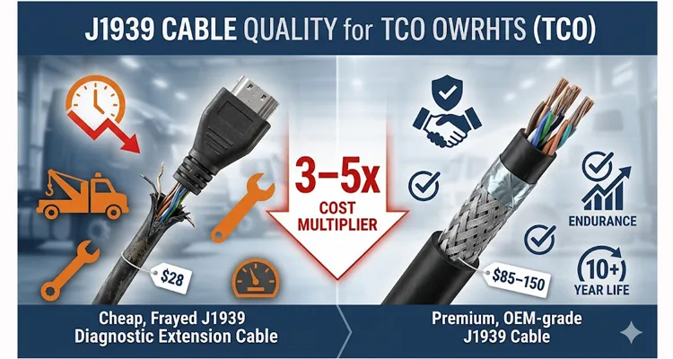
| Initial Purchase | $25–35 | $85–150 | Upfront price gap is significant |
| Technician Diagnostic Time (per failure) | 1–3 hours @ $120–180/hr | 0 hours | Intermittent failures are the most time-consuming to trace |
| Vehicle Downtime (per incident) | 4–8 hours | 0 hours | Average heavy truck downtime cost: $150–250/hour |
| Secondary Damage | Potential ECU/connector pin damage | None | Shorts or voltage spikes can damage gateway modules |
| Replacement Frequency | Every 6–18 months | 5–10 years (or indefinite) | Cheap cables rarely survive full lifecycle |
Average 3-Year TCO: A $28 cable typically costs $450–850 in hidden expenses. A quality J1939 assembly costs $85–150 and incurs no additional costs. That’s a 3–5x multiplier—not the 3x in the title, but often worse.
Why Cheap Cables Fail: Technical Root Causes
The J1939 protocol operates at 250 kbps nominal—not particularly fast by modern standards, but highly sensitive to impedance mismatches, signal reflection, and electromagnetic interference (EMI). This isn’t a USB cable carrying packets that can be retransmitted. This is a deterministic CAN bus where timing integrity matters. For a deeper understanding of how the Controller Area Network (CAN) physical layer behaves in vehicle networks, the CAN bus overview on Wikipedia provides the foundational context. For a deeper dive into the physical layer factors that separate a reliable assembly from a field failure, see our guide on J1939 cable shield, impedance, and jacket specifications.
1. Incorrect Impedance Matching
SAE J1939-11 specifies a 120-ohm characteristic impedance for the twisted-pair data lines. The full SAE J1939 series of standards defines the complete vehicle network architecture, with the -11 document specifically covering the physical layer. Quality cable manufacturers control dielectric materials and twist rates to maintain this spec within ±10–15 ohms over the full length.
Cheap cables frequently use generic twisted-pair wire with impedance drifting to 90 or 150 ohms. The result? Signal reflections at connector interfaces that cause bit errors. The ECU sees these as “sporadic” faults—codes that come and go, making diagnosis a nightmare.
2. Substandard Shielding and Drain Wire
The J1939 bus requires shielded twisted pair (STP) with a drain wire connected to pin A (shield ground) on the Deutsch 9-pin connector. I’ve cut open cheap cables and found:
- Foil shield that tears during assembly, creating intermittent ground paths
- Missing drain wire entirely
- Shield connected to pin A but not terminated properly at the other end
Without proper shielding, the data line acts as an antenna. In a heavy truck environment—alternator noise, starter currents, radio transmissions—that means corrupted data frames. The diagnostic tool sees “no ECU found” while the engine runs fine. Effective EMI suppression isn’t optional; it’s a fundamental requirement. Our field guide to CAN bus EMI shielding covers how to specify shielding that actually works in high-interference environments.
3. Connector Contact Failures
This is the most common failure I see. The Deutsch HD10-9-1939 connector family (the standard 9-pin diagnostic port) requires specific contact plating and insertion depths.
Cheap cables use:
- Nickel-plated contacts instead of gold
- Contacts that don’t meet the specified insertion force
- Incorrect gauge wire for the contact crimp barrel
The result is a connection that passes continuity when measured with a multimeter but fails under vibration. I’ve seen pins literally push back into the connector housing after a few insertion cycles, losing contact completely. The difference between a correctly terminated crimp and a cold weld failure is often invisible until the truck is on the road. Our analysis on crimp vs. solder vibration reliability explains why termination method directly impacts field failure rates. For a deeper look at why lab‑based vibration test certificates often fail to predict real‑world harness durability, see our guide on Beyond ISO 16750-3: When a Vibration Test Certificate Isn’t a Reliability Guarantee.
4. Wire Gauge and Stranding
J1939-11 specifies 18 AWG for power (pin B) and ground (pin A), with 20 AWG for the CAN pair. Cheap cables often use 22 or 24 AWG across all pins. The voltage drop on the power line—especially with longer cables—drops below the 9V minimum that diagnostic adapters require. The tool powers up but won’t communicate.
How to Verify Cable Quality: The Diagnostic Approach
If you’re responsible for procurement or maintenance, you don’t need to guess. Here’s what to test or request from your supplier.
Step 1: Resistance Testing
Using a multimeter, measure between pins C and D (CAN High and CAN Low) at the cable ends. A properly terminated J1939 cable will show 50–70 ohms due to the 120-ohm terminating resistors at each end of the bus in parallel.
Cheap cables often show open circuit (no terminating resistors) or incorrect values outside this range.
Step 2: Continuity with Vibration
This catches intermittent failures. Connect the cable to a known-good J1939 breakout box or adapter, then physically flex the cable near the connectors while monitoring continuity on all pins. A quality cable shows no fluctuation. A cheap cable often reveals intermittent breaks at the strain relief.If you encounter a break that’s invisible to a standard continuity check, our detailed guide on The Phantom Fault: How to Locate and Repair Internal Wire Breaks in OBD2 Harnesses provides the step‑by‑step torsion‑stress and micro‑voltage mapping methods to pinpoint the exact failure zone.
Step 3: Visual Inspection of Contacts
Use a jeweler’s loupe or macro lens. Look at:
- Contact plating: Gold is standard for data pins; nickel indicates cost-cutting
- Contact alignment: All pins should sit flush or slightly proud of the housing face
- Strain relief molding: Should be fully bonded to the jacket, not a separate piece that can rotate
Step 4: Terminating Resistor Verification
The J1939 bus requires 120-ohm termination at both ends. Some cheap cables omit these resistors entirely, or use surface-mount resistors that crack under vibration. A quick resistance check between CAN_H and CAN_L on a known-good vehicle diagnostic port should read 60 ohms (two 120-ohm resistors in parallel). If your cable passes that reading through, it’s correctly terminated.
Common Procurement Mistakes I’ve Seen (and Fixed)
Mistake 1: The USB Drive Procurement Model
I sat in on a procurement review last year where a fleet buyer pulled up a spreadsheet. J1939 cables were grouped under “accessories” alongside USB chargers and phone mounts. The evaluation criteria? Unit price and delivery date. No one asked about impedance, pin retention, or jacket material.
That fleet ordered 200 cables. Six months later, 23 were in a scrap bin, and three ECUs had logged intermittent bus errors that took a combined 14 hours to trace back to the cables. The $5 per-unit savings cost them roughly $4,500 in diagnostic time alone. This scenario is exactly why treating these as passive components is a mistake. A detailed breakdown of the real cost of a custom cable shows why unit price is the wrong starting point.
Mistake 2: Not Matching Type 1 vs. Type 2 Connectors
The Deutsch 9-pin diagnostic connector comes in two physical variants:
- Type 1 (Black): Larger pin F and G diameters (used on older and some current vehicles)
- Type 2 (Green): Standardized pin diameters for all pins
A Type 2 cable inserted into a Type 1 receptacle can damage the receptacle pins or fail to make contact. I’ve seen shops force-fit these, destroying the vehicle’s diagnostic port. For a deeper look at how this mismatch drives misdiagnosis and unnecessary downtime, see our guide on J1939 Type 1 vs Type 2 misdiagnosis costs.
Mistake 3: Overlooking Environmental Ratings
Heavy trucks operate in environments that kill consumer-grade electronics. A J1939 cable for under-hood or chassis applications needs:
- Temperature range: -40°C to +85°C minimum
- Oil and chemical resistance: TPE or similar jacket material
- UV resistance: For exterior runs
Cheap cables often use PVC jackets that harden and crack after exposure to diesel fuel or road salt.
How I Evaluate a Cable Supplier (Before I Even Ask for a Quote)
I don’t start by asking for a price list. I start by asking three questions.
1. “Can you show me your incoming material inspection records for the last three months?”
A supplier who can’t answer this is buying random stock from a trader. One who can—and does—usually holds ISO 9001 and IATF 16949 because those standards require traceability. I want to see that they’re testing raw cable before it ever reaches assembly. If they’re not, I walk. For fleets and OEMs requiring automotive-grade process control, our IATF 16949 PPAP zero-defect cable process outlines what a production-ready quality system actually looks like.
2. “How do you store contacts and connectors?”
This sounds trivial until you’ve seen what humidity does to unplated terminals. A shop that takes quality seriously runs a climate-controlled warehouse and can tell you their humidity range. I’ve rejected sample orders simply because the supplier couldn’t answer this.
3. “What does your final test station actually check?”
“100% tested” means nothing. I want to know: is it just continuity, or are they verifying termination resistance, shield continuity, and pinout under load? The difference between a $0.50 test and a $2.00 test is the difference between a cable that works for three weeks and one that works for three years.
When to Choose OEM Customization
Off-the-shelf cables work for standard applications. But I push for custom in two situations that procurement often overlooks.
1. Mixed Fleet Age
If your fleet spans pre-2010 and post-2020 trucks, you’re dealing with two different diagnostic port behaviors. Older Type 1 ports have larger pins F and G. A standard Type 2 cable can work, but I’ve seen intermittent contact issues that vanish when you switch to a correctly pinned custom assembly. The cost difference is negligible; the diagnostic frustration it saves is substantial.
2. Telematics Integration with Ignition Sense
A standard J1939 cable gives you CAN and power. But many telematics gateways need an ignition sense signal to know when to wake up. If you’re pulling that from pin G (which on some vehicles is ignition), you need a custom pinout that routes it correctly. I’ve had fleets spend weeks chasing “dead” gateways when the problem was simply a standard cable that didn’t carry the right signal. A custom assembly solves it at the hardware level, no software workarounds.
Custom doesn’t mean expensive when sourced from a direct factory with existing tooling. The setup costs are amortized over your order quantity, and you get a cable that exactly fits your use case.
FAQ: J1939 Cable Quality and Procurement
What’s the actual resistance range I should measure on a J1939 cable?
Between pins C and D, you should read 50–70 ohms if the cable includes termination. Between pins A and B (power and ground), you should read continuity with resistance under 1 ohm per meter of cable length.
Can a bad J1939 cable damage the ECU or diagnostic tool?
Yes. A short between the CAN lines and battery voltage (pin B) can feed 12V or 24V into the CAN transceiver, which typically operates at 5V. This can damage both the vehicle’s gateway module and your diagnostic adapter.
How do I know if I need Type 1 or Type 2 connectors?
Type 1 (black) has larger pin F and G diameters. Type 2 (green) has standardized pin sizes for all positions. If you’re unsure, use Type 2 cables—they work in Type 1 receptacles (though some very old Type 1 ports may require Type 1 pins). The vehicle’s diagnostic port color is a visual indicator: green is Type 2, black is often Type 1 but verify.
What’s the difference between J1939/11 and J1939/15—and why does it matter for my diagnostic cable?
J1939/11 is the spec that calls for shielded, twisted-pair cable with a dedicated drain wire. It’s designed for the high-EMI environment of a heavy truck engine bay. J1939/15 allows unshielded cable for simpler, low-noise applications like a cab controller.
Here’s the practical take: if your diagnostic cable is built to /15 specs, it’s essentially a cheap telephony cable in a truck environment. The alternator alone will induce enough noise to corrupt data frames. I’ve seen diagnostic tools that connect fine in the shop (engine off) fail the moment the engine starts. That’s almost always a /15 cable being used where /11 is required. A properly built /11 cable with full shielding and drain wire continuity solves it.
How often should J1939 cables be replaced?
A properly manufactured cable with quality materials and strain relief should last the life of the vehicle (10+ years) with normal use. Replace when insulation is damaged, contacts are corroded, or the cable fails electrical testing.
Can I extend a J1939 cable without signal degradation?
Yes, but with limits. Each extension adds impedance discontinuity at the connectors. Keep total cable length under 40 meters for reliable 250 kbps communication. Use quality bulkhead connectors and maintain shield continuity.
What should a J1939 cable spec sheet include?
Look for: conductor gauge (AWG), stranding, insulation material, shield type and coverage, jacket material and temperature rating, connector manufacturer and part number, contact plating, and termination resistor value and placement.
Why do some J1939 cables work intermittently with certain vehicles?
Often a grounding issue. Some vehicles require pin A (shield ground) to be connected to the diagnostic tool’s ground. If the cable’s shield is floating, the CAN transceiver may see excessive common-mode voltage.
Are molded cables better than assembled cables?
For harsh environments, overmolded strain relief is superior. It eliminates the gap between connector and jacket where moisture can enter. Overmolding also prevents the cable from rotating at the connector, which can break internal solder joints.
How can I verify a supplier’s quality claims?
Request a sample batch and perform the resistance, continuity, and vibration tests described above. Ask for test reports showing 100% inspection results. A legitimate supplier will provide them without hesitation.
Final Thoughts: Procurement as Reliability Engineering
I’ve spent two decades in cable manufacturing, and the single biggest shift I’ve seen is in how procurement understands their role.
I’ve been in enough fleet maintenance meetings to know that no one remembers what they paid for a cable six months ago. What they remember is the four-hour diagnostic hunt, the tow truck that didn’t need to be called, and the load that didn’t make the delivery window.
When I look at procurement decisions now, I don’t ask “what’s the unit cost?” I ask “what’s the cost of this decision failing at 6:00 PM on a Friday, with a truck 200 miles from the shop?” That reframes the conversation. The $28 cable starts to look expensive. The $85 cable starts to look like cheap insurance.
Need engineering support for a custom J1939 cable specification? We’ve been building these assemblies for over 20 years—direct from our ISO 9001, IATF 16949 certified facility. This isn’t a marketing claim; it’s a reflection of process controls we’ve documented in our IATF 16949 certification milestone. Whether you need custom lengths, specific pinouts, private labeling, or help validating your existing design, our engineering team works directly with you.
- Chat with our technical team on WhatsApp: https://api.whatsapp.com/send/?phone=8617307168662&text=Need+Help%3F+Chat+linda+WhatsAPP&type=phone_number&app_absent=0
- Submit your requirements through our Contact page: https://obd-cable.com/contact/
We support OEM customization across logo, brand, length, color, and AWG specifications. Every assembly is 100% tested, built under 5S management, and shipped from our climate-controlled warehouse. RoHS, REACH, and UL compliance available.
This guide reflects field experience gathered from fleet diagnostics, OEM service training, and factory engineering data. For your specific application, consult the vehicle manufacturer’s diagnostic interface requirements.
