

The Intermittent Nightmare Every Engineer Knows
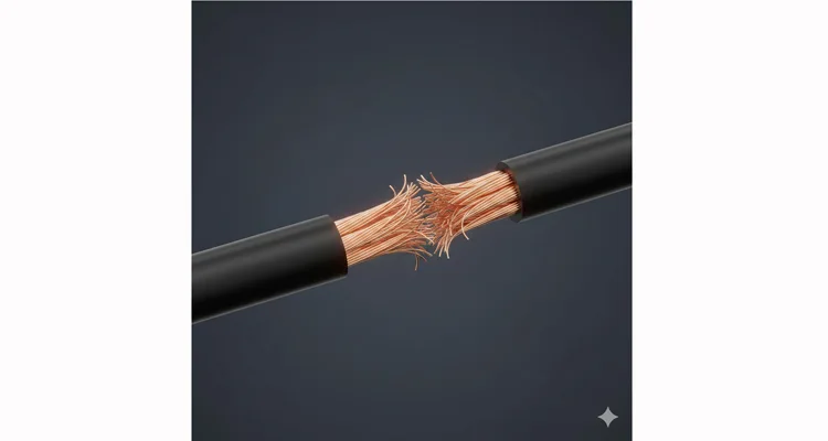
The most expensive CAN bus fault isn’t the one that bricks the ECU. It’s the one that comes and goes. Like the telematics unit that passes all factory EOL tests, only to log U0100 errors randomly across 3% of a 500-vehicle fleet after six months. Or the prototype test rig that loses communication with the DUT only when the cooling fan kicks in. You’ve replaced everything except the harness, because the harness ‘tests fine.’ That’s where the real cost accumulates—not in parts, but in indeterminate downtime and corrupted data. This is the domain of the internal conductor fracture. For a systematic approach to similar elusive issues, see our guide on how to diagnose intermittent CAN bus failures.
This is a fault that lives inside a seemingly intact OBD2 harness, hidden under insulation, often undetectable with a standard multimeter. It’s the kind of intermittent problem that consumes hours, frustrates technicians, and costs shops real money. For engineers designing diagnostic equipment or managing fleet diagnostics, it’s a reliability nightmare that standard continuity checks miss entirely.
Why Your Standard Diagnostics Fail Here
When an OBD2 port (governed by the J1962 standard) starts throwing sporadic communication errors, the instinct is to blame the ECU, the gateway, or the network. But when those components test fine, attention turns to the wiring. A visual inspection shows no cuts, no chafing. A continuity check from pin to pin passes. Voltage at the pins seems correct. Yet under real-world conditions—vibration, temperature swings, connector mating—the fault reappears.
The failure isn’t a binary ‘on/off’ switch. Think of it as a greasy hinge. Under no load, the hinge (fractured strands) can still swing and make contact. Apply the friction of real current—or the jolt of vibration—and that tenuous connection slips. This is why static resistance readings lie. Our 3-Centimeter Fracture Zone Theory is essentially that hinge’s pin: the focal point where repeated micro-motion has polished the copper strands until they can no longer grip each other under load. Most technicians stop at “wiggle and check continuity.” That method fails when the break is internal to a molded section. You need a deeper diagnostic strategy, often starting with a proper CAN bus health check using multimeter resistance diagnosis.
The 3-Centimeter Fracture Zone Theory
Through years of post-mortem analysis on returned harnesses and field failure reports, we’ve mapped a consistent pattern. Internal conductor fractures in stranded automotive wire rarely occur at a single point. Instead, they manifest across a zone approximately 3 centimeters in length. Within this zone, multiple strands fatigue and break at slightly different points, creating a region of compromised conductivity rather than a clean, total sever.
This happens because of two primary mechanical actions:
- Stress Concentration at Anchor Points: Where a harness exits a connector backshell or passes through a tight grommet, bending stress focuses on a short section. Strands on the outer radius of the bend fatigue first.
- Resonant Vibration: A specific frequency of engine or chassis vibration can cause a harness segment to resonate, creating repeated flexing at an anti-node point. This leads to work-hardening and fracture of the copper over a small area. For equipment facing harsh environments, our analysis of vibration and chemical corrosion in forestry harnesses provides relevant insights.
The 3cm zone is critical because it explains why simple “pin-to-pin resistance” measurements often read normally. A multimeter applying a small test current can still find a path through a few remaining intact strands or via oxide-conducting fracture surfaces. The problem only appears under load, when higher current is needed for CAN communication or sensor supply.
For a dedicated case study on this failure mechanism, see our in-depth analysis of the 3cm Fracture Zone in OBD2 Cables.
Step-by-Step: Locating the Hidden Break
Forget the generic “check the wiring” advice. Here’s the field-proven protocol we use in our failure analysis lab and recommend to OEM engineering teams.
The Instrumentation That Doesn’t Lie
In our failure analysis lab, we bypass the tool crib basics. Here’s what we use and why:
- Multimeter: Not just any DMM. You need true 4.5-digit resolution or better (e.g., Keysight 34465A, Fluke 87V Max) to resolve sub-millivolt drops. The auto-ranging on cheap meters adds noise. For foundational techniques, refer to our CAN bus multimeter fault tracing guide.
- Current Source: A bench power supply with constant current (CC) mode is fine. The critical spec is low output ripple (< 5mV p-p). Ripple obscures the micro-voltage drop you’re hunting for.
- Probes: Insulated T-pins are a must. Piercing the insulation to back-probe is a last resort—it creates a future corrosion point. We use tips with a 0.8mm diameter and gold plating for reliable contact.
- Torque Gauge: This isn’t for fastener tightening. A digital torque screwdriver (0.01-0.5 Nm range) lets you apply and record the exact torsional force that precipitated the fault. Reproducibility is key.
Phase 1: The Torsion Stress Test (The “Twist Method”)
Do not just wiggle. Apply controlled, localized torsion.
- Isolate the Suspect Circuit: Based on DTCs, identify the specific pin(s). For CAN faults, focus on CAN High (Pin 6) and CAN Low (Pin 14).
- Establish a Baseline Load: Using your current source, apply a 500mA constant current through the circuit from the OBD2 pin to the ECU connector pin (or simulate a 60-Ω CAN termination load). Monitor voltage drop across the entire length. Record this value.
- Section the Harness: Mentally divide the harness into 10-cm segments, starting from the OBD2 connector.
- Apply Controlled Twist: For each segment, grip firmly and apply a slow, 180-degree twist in one direction. Do not bend or pull—pure torsion. Watch the voltage drop on your meter.
- Identify the Anomaly: When you twist the segment containing the fracture zone, you’ll see the voltage drop spike erratically by 50-300mV as the fractured strands lose contact. The 3cm zone will reveal itself. Mark this segment with tape.
Phase 2: Micro-Voltage Drop Mapping
Now, pinpoint within the zone.
- Increase Resolution: Switch your multimeter to the 200.0mV DC range.
- Create a Two-Probe Setup: Connect your current source (1A load) to the OBD2 pin and the far end of the circuit. Use one meter probe at the OBD2 pin (reference). Use the second probe as a rover.
- The Mapping Pass: Starting at one end of your marked 3cm segment, place the rover probe against the insulation. Use a sharp but insulated tip to make gentle contact. You are not piercing the wire. You are measuring the surface voltage gradient caused by the internal current flow.
- Read the Gradient: Slowly move the rover probe along the harness. Over most of the length, the voltage difference between the reference and rover will change minimally (a smooth gradient). When you pass over the fracture point, you will see a sudden, sharp jump in the millivolt reading—often 10-50mV within a 5mm movement. This is the voltage drop concentrated at the break.
- Confirm: Move the reference probe to the other side of the suspected break and repeat. The jump will appear in the opposite direction. You’ve now bracketed the break within a 5-10mm window.
Five Costly Assumptions That Perpetuate Phantom Faults
- “The Ohm is Absolute”: Assuming a 1.5Ω reading on a CAN line is ‘fine.’ In our lab, we’ve traced a 0.8Ω increase on CAN-L to a 40% strand fracture rate in the 3cm zone. That extra resistance was enough to skew the differential voltage, causing intermittent dominant bit errors at high bus load. The Fix: Measure resistance under a 500mA load, not the meter’s default μA test current.
- “Continuity Equals Capability”: The cheerful beep of a continuity tester is the siren song of the haunted harness. We received a cable from a drone manufacturer that beeped perfectly, yet their UAV would drop GPS data in left turns. The Fix: Demand functional testing under dynamic conditions that mimic the actual failure mode.
- “New Harness, New Start”: Blindly replacing the entire harness is the costly last resort. It often doesn’t fix the root cause if the stressor (poor clip routing, resonant frequency) remains for the new harness. The Fix: Diagnose and correct the mechanical stress path before installing the replacement.
- “A Solder Splice Solves It”: If you simply cut out the break and solder, the stiff splice becomes the new stress concentrator. The fracture will reappear next to your repair. This is a classic example where understanding crimp vs. solder reliability under vibration is crucial. The Fix: You must address the mechanical cause and use a flexible, strain-relieved splicing system.
- “The Connector is Just an End”: Ignoring the connector backshell is a major oversight. Over 40% of these internal breaks originate within 2cm of the connector, where the wire transitions from flexible to rigid. The Fix: Always inspect this area first with the torsion test.
Validating the Repair: Beyond Continuity
A standard repair verification—checking for continuity—is inadequate. Your verification must replicate the mechanical and electrical conditions that caused the fault.
- Dynamic Load Test: After repair (proper strain relief included), apply the operational load (e.g., 500mA for CAN, 2A for power pins). While the load is applied, subject the repaired section and its immediate neighbors to the full range of motion and vibration it would see in service. Monitor voltage drop for any fluctuation >2% of baseline.
- Thermal Cycle Test: Use a heat gun and cold spray to cycle the repaired area from -20°C to 85°C (simulating engine bay extremes) over several cycles, under load. Any sign of intermittent connection indicates an incomplete repair or a secondary break.
- Return to Service Protocol: Clear codes, then monitor not just for the original DTC, but for related network stability parameters (e.g., CAN error frames, message counter resets) over an extended test drive or bench test cycle.
The Role of Harness Design & Manufacturing in Prevention
As a factory that has produced over 10 million OBD2 cables for diagnostic tools, vehicle telematics, and OEM test rigs, we see the root causes long before the field failure. The phantom fault is often a manufacturing or design issue in disguise.
Our 4-Point Prevention Build Standard:
- Strain Relief Geometry: We mold connector backshells with a specific bell-shaped strain relief. The internal bend radius for the wires is never less than 3 times the cable diameter. This prevents the 3cm fracture zone from forming at the most critical point.
- Conductor Pre-Bonding: For high-flex applications (like scan tools cables), we use a proprietary process to lightly bond the strands within each conductor with a flexible dielectric coating. This distributes flex stress across the entire strand bundle, preventing individual strand fatigue.
- Torque-Controlled Crimping: Every terminal is crimped with a servo-controlled machine that monitors force-displacement curves in real-time. An over-crimp can notch and weaken strands; an under-crimp leads to pull-out. We have the data for each pin.
- 100% In-Circuit Functional Test (ICT): Every finished cable isn’t just checked for continuity. It goes through a dynamic ICT that applies a 1A pulsed load to each pin while mechanically flexing the cable at key points. The system logs millivolt drop variations and rejects any unit showing nascent instability.
The Tools We Build to Solve This (And How to Specify Them)
If you’re an engineer designing test equipment or specifying cables for a fleet, you need to move beyond the commodity “OBD2 cable.” Here’s what to ask for:
| Feature | Commodity Cable | Engineered Solution (Our Standard) | Purpose |
| Conductor Stranding | 7×0.2mm (Stiff) | 19×0.08mm (Fine-Flex) | Distributes bending stress |
| Insulation Material | PVC | TPE (Thermoplastic Elastomer) | Higher flex life, cold-weather pliability |
| Strain Relief | Simple overmold | Dual-Durometer, Bell-Shaped Mold | Eliminates stress at connector interface |
| Shielding | Foil + drain wire | Braided copper (95% coverage) + foil | Handles repeated flex without shield tearing |
| Testing | Continuity check | Dynamic Load + Flex Test (Data Logged) | Catches early-stage fractures before shipment |
For OEM & Custom Projects: We don’t just sell cables. We provide a Failure Analysis and Design Review service. Send us your failed harness or your mechanical drawings. Our engineers will perform the torsion and micro-voltage drop analysis, pinpoint the failure mode, and recommend a design revision—often at no cost. This is the support that keeps production lines running and prevents warranty returns, integral to our IATF 16949 & PPAP zero-defect cable process.
Frequently Asked Questions (From Engineers, For Engineers)
Q1: Can’t I just use a Time Domain Reflectometer (TDR) for this?
A: In theory, yes. A high-end TDR can locate an impedance discontinuity. In practice, for a sub-3m OBD2 cable, the fracture zone often creates too small an impedance jump to reliably distinguish from connector reflections, especially if the break is intermittent. The load-based voltage drop method is more sensitive and requires far less expensive equipment.
Q2: Does wire gauge matter for this type of failure?
A: Absolutely. Using a larger gauge (smaller AWG number) for current-carrying pins (like Pin 16, +12V) is standard. But more critical is the strand count. A 22 AWG wire with 19 fine strands will outlast a 22 AWG with 7 thicker strands in a flex application by orders of magnitude. Always specify strand count, not just gauge.
Q3: Are these faults more common in certain climates?
A: Yes. Cold climates accelerate it. PVC insulation becomes stiff below -10°C, turning every wire movement into a high-stress event on the copper. We specify TPE or specially formulated cold-flex PVC for cables destined for northern markets or refrigerated vehicles. This is a key consideration in our forensic guide to reefer wiring harness failure.
Q4: How do you repair a harness in a permanently installed vehicle telematics unit?
A: Often, you can’t replace the whole harness. The solution is a surgical splice with strain redistribution. This involves: 1) locating the break via the methods above, 2) cutting out a 5cm section, 3) splicing in a new segment of higher flex-class wire (e.g., from our repair kits), and 4) adding a dedicated flex relief loop in the new section to absorb future movement.
Q5: Your website mentions IATF 16949. How does that relate to cable design?
A: IATF 16949 isn’t just a quality certificate. It mandates a preventive approach. For us, it means we must use Automotive SPICE-like processes for design validation, including FMEA (Failure Mode and Effects Analysis) specifically for wiring harnesses. We’ve formally documented over 20 potential failure modes for OBD2 cables; “internal conductor fracture due to resonant vibration” (FMEA ID: WH-07) is one. Our design rules exist to control its risk priority number. Learn more about our certification: Shenzhen Carsun Electronic Technology achieves IATF 16949:2016 certification. We also adhere to ISO 14001:2015 for environmental management.
Q6: Can you provide test data for a specific cable’s flex life?
A: Yes, upon request for OEM inquiries. Our standard test is based on a modified ISO 6722-1 (bending test). We don’t just state “10,000 cycles.” We can provide the test fixture geometry, force applied, and the resistance vs. cycle curve up to the point of failure. This data is critical for integrating our cables into your product’s reliability calculations and goes beyond basic standards, as explored in our article on vibration reliability beyond ISO 16750-3.
Q7: Do you offer custom overmolding for our proprietary connectors?
A: Yes, this is a core part of our OEM business. We’ve developed over 200 custom connector molds. The key is to involve us during your connector selection phase. We can advise on strain relief geometry and recommend connector variants that are more forgiving from a wire fatigue standpoint. Understand the investment in the true cost of a custom cable.
Q8: What’s the lead time for a custom, engineered cable sample?
A: For a fully custom design (new connector, new length, specific materials), initial samples typically take 3-4 weeks. This includes building a temporary mold, producing a small batch, and running them through our full dynamic test suite. For modifications to an existing design (e.g., a different color, your logo printed), samples can be ready in 7-10 working days.
Let’s Solve Your Phantom Fault
Intermittent faults are not a mystery; they are a measurement problem. The protocols described here—the 3-Centimeter Fracture Zone Theory, torsion stress testing, micro-voltage drop mapping—are how we transform ghosts into data points. This isn’t just theory; it’s the daily practice in our IATF 16949-certified failure analysis lab.
We don’t just sell cables. We sell the certainty that comes from building them to survive the specific conditions that create phantom faults. If your design or fleet is plagued by intermittents, the most efficient next step is often to send us a failed sample. Our standard no-cost post-mortem analysis will apply the methods in this article and provide you with a definitive failure mode and a preventive design recommendation.
- For Technical Discussion & Custom Project Scoping: The fastest way is often a direct conversation. Reach out to our engineering team on WhatsApp. Send photos of your application, a sketch of the routing, or the DTC logs you’re seeing.
- For Formal Quotes & Project Documentation: Use our Contact Page. Detail your requirements, annual volumes, and any environmental specs (temperature, flex cycles, chemical exposure). We’ll assign a project engineer who will provide a specification sheet, test data proposal, and a timeline.
WhatsApp: +86 17307168662
Contact Page: https://obd-cable.com/contact/
Let’s build something that doesn’t break.
