

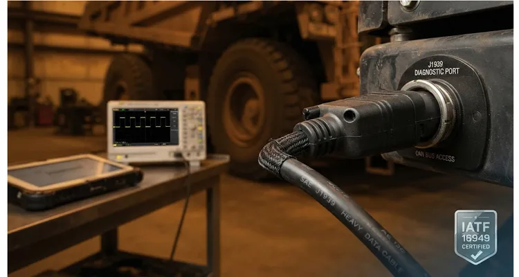
In twenty-three years on the manufacturing side, I’ve had exactly seven calls that started with “We’ve swapped everything and the bus still drops.” Six of those calls ended with a technician holding up a diagnostic cable and saying, “Wait — could it really be this?” The seventh was a defective ECU, but by then the fleet had already lost eighty-four hours of haul truck uptime chasing the wrong component. I remember that seventh case because it’s the exception that proves the rule: the physical link is almost never “just a cable.”
I started on the crimping line when we still used manual-adjustment dies and a spring gauge to set pull force. Today, the crimp height monitors in our IATF 16949 cells log force-displacement curves every three milliseconds, and I can pull up the histogram for any batch shipped in the last seven years. That shift — from artisan to statistical process control — is what separates a cable that survives a forty-g shock test from one that opens on a haul road. And I can state from experience that when a heavy-duty diagnostic link is built without the process discipline of a standard like IATF 16949, you’re not saving money — you’re building in network downtime that will cost you later, often at the worst possible moment.
The Physical Layer Is Never “Just a Cable”
I’ve walked enough fleet maintenance bays to know the pattern: the conversation always opens with ECU software revisions, CAN message scheduling priorities, and where the termination resistors sit on the backbone. The cable connecting the scan tool or data logger to the vehicle’s diagnostic connector? It’s treated as an afterthought — a generic accessory. That’s the mistake I see repeated across mining, construction, and heavy-duty trucking.
How a 108-Ohm Impedance Drift Triggers a CAN Bus-Off
We measure differential impedance on every CAN-ready cable that leaves our test bench, and we’ve collected enough data to know that a connector assembly running at 108 ohms will still pass a static bench check nine times out of ten. Put it on a vibration table at twenty-two hertz — the dominant frequency we recorded on a mining-class haul truck chassis — and that same cable starts spitting error frames inside twenty minutes. The controller doesn’t go bus-off instantly. It ticks over from error-active to error-passive after about fourteen hundred corrupted frames, which on a 250 kbps CAN bus loaded at thirty-five percent takes roughly eight seconds. After that, the node disappears from the network. If that node is your diagnostic interface, you just lost your window into the machine.
The Real Cost of a Marginal Diagnostic Cable: A Pilbara Case Study
In 2018, a Pilbara iron ore operation running a mixed fleet of two-hundred-ninety-tonne haul trucks started losing telemetry sync between 2 a.m. and 4 a.m., coinciding with the coldest part of the desert night cycle. They replaced six TCUs at a cost they later pegged at eleven thousand four hundred dollars each, installed and calibrated — and the problem persisted. When the pass-through cable finally reached our bench, I sectioned the strain relief under a microscope and found the drain wire had stress-fractured at a grain boundary visible only after etching. The cable had passed a supplier’s continuity test, but the shield lifted under thermal contraction of the jacket at four degrees Celsius. The mine’s maintenance superintendent later told me they logged the total cost of that single fault at just over three hundred twelve thousand dollars in delayed production — a number he calculated by taking their per-truck-hour idle cost of two thousand six hundred dollars and multiplying by one hundred twenty lost hours. That cable came with a certificate, but it wasn’t manufactured under anything resembling an IATF 16949 process control plan.
What IATF 16949 Actually Changes in Cable Manufacturing
PFMEA and Automated Error-Proofing in Diagnostic Cable Assembly
Every PFMEA we write for a 9-pin Deutsch cable scores failure modes on a one-to-ten severity scale, and our internal rule is that anything above severity seven must trigger an automated, in-station error-proofing check — not a downstream inspection. That’s why our overmold stations use a vision system that measures gate flushness to within 0.15 millimeters, and if it’s out, the fixture locks and the line stops. It’s not mandated by the standard. It’s mandated by twenty years of learning that a 0.2-millimeter proud gate on the connector face will eventually hang up on a vehicle-side retention clip and crack the seal.
Factory Floor, 5S Discipline, and Climate-Controlled Storage
When you walk into our facility — a direct factory, not a trading company — you see the result of that planning. We operate under ISO 9001 and ISO 14001, with IATF 16949 governing the automotive-grade processes, a quality system we maintain alongside our ISO 14001:2015 certification. The assembly cells are laid out in 5S discipline: everything has a marked place, all tooling is calibrated on a documented schedule, and every crimp height is measured with a micrometer at the start, middle, and end of a production batch. The warehouse is climate-controlled because we learned over twenty-plus years that even slight oxidation on bare copper terminals can push contact resistance over spec, and you’ll never catch it with a simple continuity beeper.
4-Step Quality Inspection and Full Material Traceability
The four-step quality inspection isn’t a marketing phrase; it’s the practical minimum we landed on after shipping millions of diagnostic cables. Step one is an automated one hundred percent continuity and hipot test, checking every pin for opens, shorts, and dielectric strength. Step two is visual inspection under magnification — every molding gate, every crimp barrel, every laser marking. Step three is an impedance and signal integrity check on a network analyzer for CAN-ready cables, verifying differential impedance and insertion loss on a sample basis from each lot. Step four is a physical pull-test and mating-cycle test on production samples to catch the slow degradation that pure electrical testing misses.
All of this is done on cables that use a full-plastic overmold design, fully compliant with RoHS and REACH. No metal shells that can corrode and form stray ground loops. Every material — from the TPU jacket to the gold flash on the terminals — is documented and traceable to its supplier lot. That traceability is a hard requirement under IATF 16949, and it means that if a field issue ever occurs, we can quarantine the exact production window, down to the reel of wire and the operator shift. I’ve had to do that exactly twice in the last eight years, and both times the root cause was found and contained within forty-eight hours. Try that with a generic supplier.
The Four Numbers That Tell You If a Cable Is Network-Safe
If you’re evaluating a diagnostic cable for a heavy-duty CAN application, ignore the marketing copy. Four measured values separate a cable that will run for years from one that will ruin your morning in the middle of a diagnostic session.
Field Data: When a 178-Ohm Connector Ruined a Diagnostic Session
We’ve tested incoming connector samples from fourteen different offshore suppliers over the last five years. The worst one measured 178 ohms differential impedance right at the connector body, caused by an untwisted parallel run of eleven millimeters inside the backshell that the designer hadn’t accounted for in the 3D model. On a benchtop, it passed. On a vehicle with the engine at eighteen hundred RPM, the error frame rate jumped to seventy-two frames per second — exactly the kind of RPM-dependent phantom fault that disappears the moment a static check is performed. That’s what the specs look like when they’re real.
- Differential impedance at 1 MHz: Must be 120 ohms ±12 ohms. Measured between CAN_H and CAN_L with the far end terminated. We’ve pulled production cables off our own bench that drifted to 150 ohms — a 25% deviation that would still pass a low-cost supplier’s continuity-only test, yet it guarantees bit sample jitter at the first sign of vibration.
- Contact resistance per pin: Should stay below 10 milliohms initially and after environmental cycling. In our incoming inspection of non-automotive connectors, we’ve recorded initial values of 50 milliohms — already five times our acceptance threshold — that then climb to over 200 milliohms after salt spray. That added resistance attenuates the signal edge and increases bit sample jitter.
- Capacitance between CAN_H and CAN_L: Should be under 40 picofarads per meter for the twisted pair, and total connector capacitance kept as low as possible. Excess capacitance rounds off the differential signal, shrinking the eye diagram until the transceiver can’t reliably distinguish recessive from dominant bits.
- Insulation resistance between any pin and shield at 500 VDC: Should be greater than or equal to 100 megohms. Moisture ingress in a poorly sealed overmold can drop this to the kiloohm range, pulling the bus common-mode voltage off-center.
We verify these four numbers on our in-house fixtures before any batch of J1939 Type-2 cables ships. Not as a spot-check — as a one hundred percent test for continuity and hipot, combined with statistical process control on impedance and capacitance. If a lot shows a capacitance shift, we stop the line and find out why. That discipline comes from living inside an IATF 16949 quality system, not from a CEO who decided to slap the logo on a certificate.
Common Field Mistakes and How to Spot Them
Field-Tested Root Cause Patterns Across Heavy-Duty Fleets
Over the years, certain mistakes repeat across different fleets and OEMs. The table below captures the ones that most often turn a diagnostic cable into a network problem, and where we’ve personally seen them.
| Symptom | Root Cause | Quick Check | Observed On |
| Intermittent bus-off when cable is moved | Broken drain wire inside strain relief | Flex the cable near the connector while monitoring CAN error frames | Hitachi EX3600 shovel, 2022 investigation |
| CAN errors only when engine is running | Shield not connected at the diagnostic connector end, allowing radiated noise from injector PWM | Measure shield continuity from DB9/Deutsch shell to vehicle chassis while wiggling | EMD GP40 locomotive repower, 2019 |
| High error rate, normal-looking bus voltages | Incorrect pinout (CAN_H and CAN_L swapped, or termination pin miswired) | Use a breakout box; verify with DMM against SAE J1939-13 assignments | Multiple transit bus OEMs during first-article cable integration |
| Tool powers on but no communication | Missing ground or power pin, or undersized wire gauge causing voltage drop on 24 V supply | Load-test the power pair: measure voltage under a 500 mA load | Volvo L220H wheel loader, field diagnostics campaign |
| Bus works with one scan tool but not another | Termination resistance inside the cable assembly interferes with backbone termination | Unplug cable, measure resistance between CAN_H and CAN_L; it should be open (or have a user-switchable terminator) | Independent workshop with mixed-brand diagnostic interfaces |
One case I recall involved a bus OEM using a pass-through diagnostic Y-cable to connect a data logger during durability testing. Random CAN lockups plagued the test for six weeks. The Y-cable had been built by a local harness shop — beautifully sleeved, but with a hidden manufacturing defect: the two CAN_H lines were soldered together inside a heatshrink bundle, creating an impedance stub. A TDR measurement on our bench showed an open circuit-like reflection at exactly 1.3 meters from the connector, the length of that stub. The solution was a cable assembly where all junctions are controlled in a molded node, with impedance continuity verified on a VNA. That’s the kind of engineering support we provide when an OEM brings us a problem, not just a part number.
How We Stopped a Recurring CAN Bus Lockup for a Bus OEM
To give you a concrete example of how cable construction ties directly to network uptime: a heavy-duty electric bus manufacturer approached us after field failures in their remote diagnostics port. The symptom was a “Check Network” light on the dash and a total loss of the J1939 diagnostic session, occurring roughly once every two thousand kilometers across twenty percent of the fleet.
The Deutsch 9-Pin Redesign: Crimped Shield, No Solder
We traced the issue to the 9-pin Deutsch diagnostic connector on the vehicle side. The original design used a cable assembly with a metal backshell and a separate internal ground wire soldered to the shield. Vibration at the engine mount slowly work-hardened the solder joint until it fractured. Because the connector still felt tight, technicians would blame software and start swapping VCUs — a part that costs five thousand dollars each, not a small figure.
Our solution was a fully overmolded full-plastic connector body with the shield braid directly crimped under a controlled compression barrel, then encapsulated inside the thermoplastic mold. No solder, no metal shell, no moving internal wires. The OEM asked for custom branding with their logo and a specific orange jacket color to match their safety protocol, and they needed it in 18 AWG for the power pins to support a diagnostic tablet that drew more current than the legacy pinout expected. We adjusted the wire gauge, laser-etched their part number into the mold, and delivered a pre-production batch within four weeks — all under the same IATF 16949 process controls.
Fleet-wide failure data twelve months later: zero CAN bus lockups attributable to the diagnostic connector. The engineering manager told us, “I stopped thinking about the cable as a purchase item and started treating it as part of the network specification.” That’s the mindset shift we’re after.
Step-by-Step Verification After Replacing a Diagnostic Cable
If you’ve just swapped a suspect cable, don’t assume the problem is fixed because the error light went off. A marginal cable can work for days under lab conditions and fail on a rough road. Here’s the verification sequence we recommend, and that we follow when we commission a custom harness for an OEM:
The 4-Step Post-Installation Protocol
- Resistance baseline: With the cable disconnected from everything, measure resistance between all pins and the shield, and between CAN_H and CAN_L. All should be open (greater than 1 megohm). Then short the far-end CAN_H to CAN_L and verify the near-end reads 120 ohms plus or minus five ohms if a termination is present.
- Voltage under load: Connect the cable to the vehicle diagnostic port. With the scan tool or data logger powered on, measure the voltage at the tool end on the power and ground pins. The drop should be less than 0.5 volts for a 24-volt system. If it’s more, the wire gauge is too high (too thin) or a pin has poor contact.
- CAN physical layer integrity with scope: Use an oscilloscope in differential mode on CAN_H and CAN_L. With the cable connected and the network active, you should see clean square waves with 2 volts peak-to-peak differential. Look for ringing or slow edges — if you see them, do the same measurement directly at the vehicle connector. If the signal is clean at the vehicle but degraded through the cable, the cable has an impedance problem.
- Error frame count under load: Use a CAN monitoring tool to check the bus error rate. On a healthy J1939 bus, you should see zero error frames during steady-state operation. Even one error frame per minute is a red flag. Run the engine through its RPM range while flexing the cable by hand. If error frames appear, the cable isn’t ready for the field.
I’ve seen fleets skip step four, deploy a thousand cables, and then spend months chasing intermittent telemetry gaps that could have been caught in a thirty-second bench test. The cost of a proper verification rig — a few thousand dollars — pays for itself the first time you avoid a single field escalation, just as we’ve documented cases where a twenty-three-cent resistor missing from a harness triggered a fleet-wide downtime event.
Why We Don’t Ship a Single Cable Without a Full Network Bench Test
This brings me to something that engineers appreciate but procurement departments sometimes don’t understand: why we test every single assembly, not just a sample. A generic cable factory might pull ten units from a batch of a thousand, run a continuity check, and call it a day. In an IATF 16949 environment, that’s not acceptable because the failure modes on a diagnostic cable assembly are often one-off manufacturing defects — a terminal that wasn’t fully seated, a slight void in the overmold, a whisker of copper that touched the shield.
100% TDR Testing and Impedance Anomaly Detection
Our one hundred percent testing is automated, but it’s not trivial. Every cable passes through a fixture that checks continuity, hipot at 500 volts DC, and a pre-programmed pinout verification. For CAN-specific cables, a second station performs a time-domain reflectometer (TDR) check looking for impedance anomalies larger than ten percent of nominal. A cable that passes continuity but has a hidden impedance bump from a crushed dielectric gets flagged and pulled. That’s the difference between “tested” and “network-qualified.”
Our certifications — CE, UL where applicable, and full material compliance to RoHS and REACH — are not just stamps. They are living requirements that govern what raw materials enter the building. Every batch of PVC or TPU compound is tested for restricted substances before it touches the extruder. The climate-controlled warehouse ensures that even in high-humidity months, the moisture content of hygroscopic materials stays within spec. These are details only a direct factory with two decades of experience and a deep engineering team would care about, but they directly affect whether your cable will still communicate cleanly after a year parked outside in Houston or Dubai.
Frequently Asked Questions from Heavy-Duty Integration Teams
1. Does an IATF 16949 certification guarantee a better cable, or is it just paperwork?
It doesn’t guarantee anything by magic — but it forces the manufacturer to implement failure prevention controls that directly reduce defects that cause network problems. An IATF 16949 factory is audited for process capability, traceability, and continuous improvement. When you buy from one, you’re not relying on final inspection luck; you’re buying a process that has already predicted and prevented most failure modes.
2. Can you match our existing cable’s exact wire color, jacket material, and printing?
We keep thirty-seven base TPU color formulations in our climate-controlled compound storage, and we can match any Pantone within a Delta E of 1.2. When a European rail OEM needed RAL 2004 pure orange for a safety-critical diagnostic harness, we extruded five color chip samples, air-freighted them for on-site approval, and had the final formulation locked within eleven working days. Logo, branding, and laser-marked pinout tables are standard — not a special service.
3. What does “100% tested” actually mean for a diagnostic cable?
It means every single assembly is powered up on a test fixture that checks every pin for continuity, isolation, and hipot at working voltage. On CAN cables, we also verify the termination resistor value if present, and on a lot-by-lot basis, we run TDR and VNA sweeps. No sample-based AQL acceptance for safety-critical diagnostics.
4. Do you support SAE J1939-15 unshielded twisted pair as well as shielded?
We build both, and we can advise on which one makes sense based on your vehicle’s electromagnetic environment. The tooling and terminal crimp parameters change slightly, but it’s within our standard process.
5. What happens if a cable fails due to vibration after months in the field?
Because we have full traceability under IATF 16949, we can investigate the exact production lot and determine if it was a material defect, a process drift, or an application stress we didn’t account for. That engineering analysis is provided to the customer, and we often use it to jointly refine the design — maybe adding a different strain relief geometry or specifying a thicker jacket. That kind of loop is impossible with a catalog distributor.
6. Can you provide a cable with a switchable 120-ohm termination resistor for a CAN diagnostic tool?
Absolutely. We embed a small PCB with a soldered termination resistor directly inside the overmold, activated by a sealed slide switch or a pushbutton that can handle the mating cycles of a busy workshop floor. No external dongles, no loose parts.
7. What lead times should I expect for a custom heavy-duty diagnostic cable assembly?
For a new design that requires custom overmold tooling, typical lead time is four to six weeks to first article samples. For a repeat order with existing tooling, two to three weeks. Expedited engineering support is available for urgent field issues.
8. Does your facility hold UL, CE, and other certifications?
We maintain UL certification for cables where required by market regulation, along with CE marking, and all materials comply with RoHS and REACH. Our facility is certified to ISO 9001, ISO 14001, and IATF 16949.
9. What is the benefit of a full-plastic overmold design compared to metal backshells?
It eliminates corrosion and stray ground paths, removes the risk of a loose metal set screw migrating into a signal pin, and achieves a better moisture seal by bonding directly to the jacket. It’s also lighter — critical when you’re spec’ing a diagnostic port on an electric vehicle where every gram matters.
10. We are an OEM engineering a new heavy-duty data link connector system. Can your team support the connector selection and pinout definition?
Yes. We regularly work with OEM engineering teams to select the optimal connector family — Deutsch DT, HD10, M12, or custom — and to define pin assignments that support not just diagnostics but also firmware flashing and high-speed Ethernet if required. Reach out through our contact page or on WhatsApp, and we’ll set up a technical call.
If Your Network Uptime Depends on a Diagnostic Link, Let’s Talk Engineering
I’ll close with something I’ve learned from too many late-night debugging sessions in bus depots and mine workshops: the most reliable diagnostic cable is the one you never have to think about. It just works, for years, through dust and vibration and temperature swings, and it never becomes the reason your technician can’t read a fault code when a machine is down.
That doesn’t happen by accident. It happens because someone on the factory floor checked the crimp height at 10 a.m. and again at 3 p.m. It happens because the warehouse where the cable sat before shipping was climate-controlled and the components were protected from humidity. It happens because the design avoided a metal shell that would eventually fret and corrode. It’s a thousand small decisions that sum up to a cable you can trust on a network you can’t afford to lose.
We don’t make a brochure for every cable we ship. But every cable that leaves here has a twelve-digit traceability code linking it to the reel of copper, the cavity number in the mold, and the technician who ran the hipot fixture. That’s the warranty that matters on a Pilbara haul road at 2:30 a.m.
If you’re fighting an elusive CAN bus fault that keeps pointing back to the diagnostic connector, or if you’re specifying a data link for a new heavy-duty platform and you want to treat the cable as a proper network component, not an accessory, we should talk. No catalogs, no price lists — just an engineering conversation about what you need.
Get in touch with our engineering team directly:
- WhatsApp: Chat with us
- Contact Page: https://obd-cable.com/contact/
We’ll discuss your application, the connector system, the environment, and what’s going to keep that network up when it matters.
