

Your scan tool powers on, connects, and then… the data stream disintegrates. PID values dance erratically, ECUs drop offline, or the entire diagnostic session collapses the moment a heavy load engages. The fault isn’t in your software or the vehicle’s computer. It’s in the electrical chaos around you—and your cable is delivering it straight to the CAN bus. In agricultural, industrial, or mining environments, EMI (Electromagnetic Interference) isn’t an intermittent fault; it’s the baseline operating condition. This isn’t theory. This is the field-proven method to reclaim diagnostic reliability.
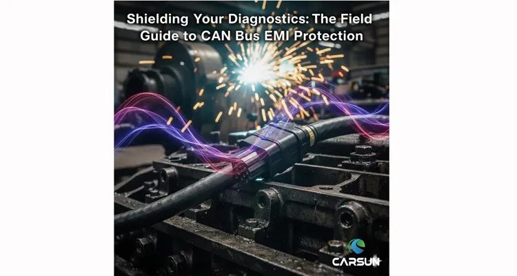
CAN Bus EMI Protection in Real-World Noise Factories
Forget controlled labs. CAN bus EMI protection becomes a critical skill in these high-threat zones:
Agricultural Machinery
Inside the cab is quiet, but beneath it lies an electrical storm. PWM-controlled hydraulic valves don’t switch cleanly—they slam between states, injecting broadband noise directly past the J1939 diagnostic port. The alternator’s diode trio adds a piercing, high-frequency whine to the mix.
Industrial & Mining Sites
Here, EMI is a blunt force instrument. High-current solenoids, variable-frequency drives, and, most aggressively, DC arc welders dominate. I’ve witnessed a single misplaced welding ground clamp channel enough noise through a machine frame to fatally disrupt the entire CAN bus network.
Fleet Workshops
Deceptively simple environments are often the trickiest. The combined hum of battery chargers, fuel pump relays, and adjacent engines idling can generate just enough conductive and inductive coupling to cause phantom intermittent OBD2 communication faults that vanish when the vehicle is repositioned.
Refrigerated Transport (Reefer Units)
The compressor clutch is a high-energy transient event, not a switch. Each cycle hammers the power line with a voltage spike. Route a standard diagnostic cable alongside this power run, and you’ve engineered a perfect antenna for conductive EMI.
Aftermarket Device Integration
Installing a non-OEM telematics unit, camera, or LED light bar with inadequate power filtering isn’t just adding a device; it’s installing a dedicated noise transmitter directly onto your vehicle’s most sensitive data network.
The Root Cause: How EMI Ambushes Your CAN Bus Signals
Visualize the CAN differential pair (CAN_H and CAN_L) as a precisely balanced scale. The receiver reads the minute difference in voltage between them. EMI acts like random weights thrown onto one side of that scale. If the imbalance (noise voltage) is too great, the intended signal becomes indecipherable—corrupting the data stream. Here’s the precise failure mechanism:
Coupling: The Three Pathways for Noise Invasion
Disruptive energy doesn’t need a direct wire; it couples onto your diagnostic cable. In noisy environments, three primary paths exist:
- Conductive Coupling: Noise piggybacks on a shared power source, like a noisy 12V socket powering your scan tool.
- Inductive Coupling: A changing magnetic field from a nearby high-current cable (e.g., a motor lead) induces a disruptive current loop in your data lines. Running parallel to power cables guarantees this issue.
- Capacitive Coupling: A changing electric field jumps across poor insulation. Thin, low-quality cable jacketing is highly vulnerable.
The Shield Failure
An unshielded cable, or one with a shield terminated by a single “pigtail” wire, provides no meaningful barrier. It’s a colander, not a firewall. Noise floods the internal signal conductors.
Signal Integrity Collapse
The EMI superimposes itself onto the critical differential voltage. When this noise exceeds the receiver’s threshold, it flips bits. While the Controller Area Network (CAN bus) protocol has robust error-checking, a sustained barrage leads to error frame overload, bus-off states, and total communication failure—manifesting as persistent OBD2 port not communicating errors on your display.
This is why a consumer-grade OBD2 cable is an active liability in industrial settings. It’s not just a passive connector; it’s an optimized antenna for interference. For foundational theory, the Wikipedia entry on Electromagnetic Compatibility is an excellent resource.
Step-by-Step Field Guide to Diagnosing and Mitigating EMI
When facing erratic communications, replace guesswork with this diagnostic sequence.
Step 1: Isolate the Environmental Variable
Does the failure only occur in a specific location (near a welder) or during a specific machine action (PTO engagement)? If communications are stable with the engine off but fail immediately at idle, you have a prime EMI signature.
Step 2: Perform the Definitive “Pull Test”
This is the most powerful field diagnostic. Physically lift and reroute the diagnostic cable away from engine blocks, harness bundles, and metal chassis. Suspend it in free air. If the signal clears, you have confirmed radiated EMI coupling and identified the need for a properly shielded diagnostic cable.
Step 3: Audit Connections and Ground Integrity
A high-impedance ground at the diagnostic connector (notably Pin 4 on the 9-pin J1939) is a major noise entry point. Verify it is clean, tight, and has solid continuity back to the battery negative. This step alone resolves many seemingly random OBD2 port not communicating issues.
Step 4: Deploy a Shielded Diagnostic Cable for EMI Protection
Swap the generic cable for a purpose-built one. The specification gap between a typical “shielded” cable and one built for survival is stark and measurable:
| Key Characteristic | Typical “Shielded” Diagnostic Cable | Engineered High-EMI Cable (Our Standard) |
| Shield Construction | Single-layer aluminum foil (Foil) | Braid + Foil (Tinned copper braid over foil) |
| Shield Coverage | < 60% (contains gaps) | ≥ 85% (high-density, overlap weave) |
| Termination Method | Single-point “pigtail” solder | 360° circumferential crimp to connector shell |
| Vibration Reliability | Solder joint prone to fatigue failure | Crimp bond is integral and vibration-proof |
| Result on CAN Bus | Prone to error frames in noise | Maintains industrial-grade signal integrity |
The shield must be a woven copper braid (not just foil) for durability and complete coverage, and it must be terminated via a 360-degree clamp to the metal connector shell for a low-impedance ground path. Our manufacturing discipline, governed by IATF 16949 certification, mandates this crimped termination over soldering for guaranteed reliability. This philosophy is detailed in our process guide: IATF 16949 Pre-Production Checkup.
Step 5: Utilize a Breakout Cable for Oscilloscope Diagnosis
For persistent, complex noise, a J1939 breakout cable is non-negotiable. It provides direct access to the backbone signals for an oscilloscope. Look for ringing, overshoot, or high-frequency “hash” obscuring the clean CAN square waves. Our J1939 9-pin Pigtail Breakout Cable is constructed for this task, with reinforced sockets for repeated probe insertions.
5 Common Mistakes That Guarantee CAN Bus EMI Failures
- Deploying an Unshielded Cable in an Industrial Setting: The cardinal error. It’s attempting to stop a pressure washer with a screen door.
- Daisy-Chaining with a Passive OBD2 Splitter Y Cable: Connecting multiple devices (e.g., telematics + scanner) via a simple splitter imbalances network termination and creates “stub” lengths that act as efficient EMI antennas. Use an active, managed splitter. We dissect this problem here: OBD2 Splitter Cable Problems Fix.
- Neglecting Shield Grounding: An unterminated shield isn’t neutral; it becomes a resonant antenna, actively amplifying noise. The ground connection must be direct and low-impedance.
- Routing Data Cables Parallel to Power Lines: Even short parallel runs guarantee inductive coupling. Always cross power cables at a 90-degree angle.
- Assuming All “Shielded” Cables Perform Equally: The efficacy is in the details: braid coverage percentage, drain wire gauge, and crucially, the termination method. The long-term cost analysis is critical: Shielded vs. Unshielded J1939 Cable TCO Analysis.
How to Confirm Your EMI Fix is Actually Working
Move beyond “it seems okay.” Validate with objective criteria:
Validation Checklist
- Stable Parameter Data: All live data PIDs remain rock-solid, with no erratic jumps or dropouts when known noise sources are active.
- Zero Communication Error Counts: Advanced diagnostic software should show no increment in CAN Error or Bus-Off counters.
- Consistent Module Connectivity: All network ECUs respond to queries without timeouts, both at idle and under load.
- The “Noise Test” Passes: Deliberately re-engage the suspected noise source (start the welder, cycle the hydraulic system). The diagnostic session must remain 100% stable. Passing this test is definitive proof of success.
Engineering Solutions: The Right Tools for the Noisy Job
A standard cable is a point of failure. The correct component is a shielded diagnostic harness, engineered as a controlled-impedance transmission line. Below are the specifications we validate for high-EMI applications:
For Direct, Shielded Connections
Our heavy-duty J1939 diagnostic cables employ a double-layer shield (foil + ≥85% braid) with a 360-degree circumferential clamp termination. This EMI shielding is just one pillar of reliability. These cables are engineered from the ground up for harsh environments, with jacketing and construction selected to endure abrasion, chemicals, and flex fatigue—principles detailed in our guide: J1939 Cable Durability in Agriculture
For Multi-Tool Setups in Harsh Conditions
Prevent bus conflicts with our OBD2 to J1708/J1939 Dual Data Stream Splitter Cable. Its architecture allows a telematics unit and a diagnostic tool to coexist without inducing the signal integrity issues inherent in passive splitters.
For Legacy Machine Diagnostics
Need compatibility with older equipment? Our Cummins J1708 to J1939 Diagnostic Cable ensures full protocol access. Shielding is equally critical here, as legacy electrical systems are often noisier. Understand the protocol context: J1708 vs J1939 Protocol Comparison Guide.
These solutions stem from 20+ years of direct factory experience solving tangible problems, not stocking catalog items. Each unit undergoes a 4-step quality inspection in a climate-controlled, 5S-managed facility. Material compliance is assured via RoHS and REACH.
FAQ: EMI and CAN Bus Diagnostics
Q1: Can EMI physically damage my ECU or scan tool?
A: Direct hardware damage requires extreme, sustained transients (e.g., a welding ground fault). Far more commonly, the CAN transceiver is overwhelmed by noise, hits its error limit, and enters a “bus-off” state—a protective software reset, not physical damage.
Q2: My diagnostic cable is shielded, but I still have issues. Why?
A: The shield is likely improperly grounded (a “floating” shield), or noise is entering via the power pin. Verify the shield’s ground connection at the connector. Also, power your scan tool from its internal battery, not the vehicle’s noisy 12V system.
Q3: Are ferrite chokes/clamps useful for CAN bus EMI?
A: Ferrites add impedance at very high frequencies. They can mitigate a specific resonance on a well-designed cable. Using them to compensate for a missing or poorly grounded shield is treating a symptom, not the root cause.
Q4: How does CAN bus EMI relate to intermittent OBD2 communication faults?
A: They are frequently identical. EMI is a primary driver of intermittent faults. The noise induces transient errors, causing timeouts and dropouts that appear random. Our systematic approach is here: Systematic Intermittent OBD-II Communication Fix.
Q5: Is twisting the CAN wires inside a cable important?
A: Absolutely critical. The consistent twist ratio ensures both wires in the differential pair experience near-identical interference (common-mode noise), which the receiver then cancels out.
Q6: What’s the difference between EMI and RFI?
A: For vehicle network purposes, the practical distinction is minimal. Radio Frequency Interference (RFI) is a subset of EMI at higher frequencies. The mitigation principles—shielding, grounding, filtering—are identical.
Q7: Do I need a special tool to diagnose EMI?
A: An oscilloscope with a differential probe is the definitive tool for visualizing noise on the CAN signals. However, the “Pull Test” and swapping in a known-good, fully-shielded cable are extremely effective field diagnostics.
Q8: We manufacture machinery. How do we design EMI resistance into our diagnostic port?
A: This is an OEM-level engineering integration task. It involves embedding filtering (common-mode chokes, TVS diodes) at the port interface, ensuring a pristine chassis ground for the connector shield, and specifying harnesses to transmission-line standards. We collaborate on such custom cable assembly designs, applying PPAP rigor and IATF 16949 discipline. See our certification foundation: Shenzhen Carsun IATF 16949:2016 Certification.
Q9: Can poor-quality connectors contribute to EMI problems?
A: Decisively yes. Loose mating, corroded pins, or plastic connector shells that prevent shield grounding will nullify even the best cable design. Connector integrity is a non-negotiable pillar of the shielding system.
Q10: Where can I learn about the specific pinout to check my grounds?
A: Precise knowledge is power. Our technical reference, J1939 Connector Pinout Decoded, details every signal, including the essential shield and chassis ground points.
Time to Silence the Noise
Operating in a noisy environment shouldn’t mean surrendering to corrupted data. By understanding how EMI attacks CAN bus signals and deploying correctly engineered, shielded tools, you transform a chronic, time-consuming problem into a resolved one. The objective is diagnostic certainty, regardless of the electrical chaos nearby.
This is the standard of reliability we design into every solution. If your operations are hindered by unpredictable faults or communication loss in harsh electrical settings, let’s engineer a permanent resolution.
Have a persistent noise scenario or a custom machine integration challenge? Our engineering team provides direct, application-focused support.
- Discuss your specific application with our engineers via WhatsApp: +86 17307168662
- Or, submit detailed requirements for a custom shielded cable solution via our Contact Page: Contact Us
We specialize in OEM & custom solutions—length, connector types, branding, and most critically, electrical and mechanical specifications crafted to endure within your unique noise factory.
