

We got the call on a Tuesday. A fleet telematics provider had twenty data loggers failing intermittently across a mixed truck fleet. Every few hours, the CAN bus would lock up, then recover. No DTCs, no damaged wiring visible. The field techs swapped loggers, replaced OBD connectors, and even flashed new firmware. Nothing fixed it. Finally, an engineer put a scope on the CAN lines and saw something odd: the recessive voltage was not sitting where it should. The common mode voltage had drifted nearly four volts above the CAN transceiver’s allowable range. The receiver couldn’t reliably detect dominant bits. Three weeks of diagnostic labour, a fried gateway module, and several truck rolls later, the bill landed at a little over three thousand five hundred dollars. The root cause? An invisible electrical shift that most CAN bus troubleshooting guides never mention.
I’ve seen this story repeat itself in mining equipment, refrigerated trailers, EV battery test benches, and agricultural harvesters. The symptoms change — corrupted frames, error-passive state, phantom node dropouts, even physical transceiver damage — but the underlying mechanism is almost always the same. It’s called common mode voltage shift, and it’s one of the most expensive and least understood electrical noise problems in vehicle and industrial networks.
What Common Mode Voltage Actually Means, Seen From the Silicon Side
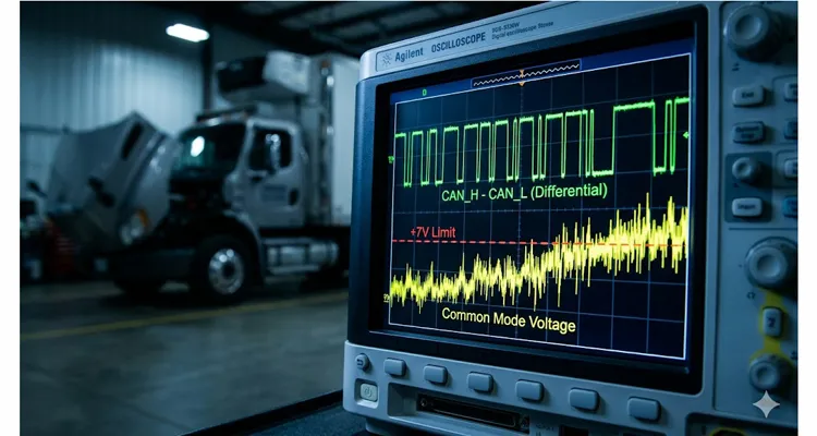
When I’m on a service call and someone tells me the CAN bus is “clean,” I grab a differential probe and subtract CAN_H minus CAN_L. That picture shows exactly what the microcontroller firmware expects — sharp recessive-to-dominant transitions. Now switch to two single‑ended channels, both referenced to the transceiver’s local ground, and set the scope to average them with a Math trace. That wandering trace — the instantaneous common‑mode voltage — is what the receiver’s input stage actually rides on. Open a datasheet for any HS‑CAN transceiver — a TJA1040, an MCP2551 — and the absolute maximum ratings table lists a common mode input range of ‑2 V to +7 V, as defined by the ISO 11898-2 CAN bus physical layer standard. Inside the chip, a resistor divider biases the receiver’s decision threshold. Push the common-mode beyond that window, and the divider saturates. Recessive and dominant states blur, and the controller starts logging bit errors nobody asked for.
In a well‑maintained passenger sedan with a factory‑intact chassis ground and a healthy battery, you might measure around 2.5 V of common mode voltage. Trouble starts when different nodes on the bus sit at different ground potentials, when large common‑mode transients are injected from nearby high‑current circuits, or when the CAN cable assembly turns into an antenna through poor symmetry. Once that happens, you get silent data corruption, bus‑off events, and thermal stress on transceiver ESD diodes they were never designed to handle continuously.
Where the Three Thousand Five Hundred Dollar Common Mode Shift Comes From
Let me walk through a field case that cost exactly that much. A refrigerated trailer body builder integrated a CAN‑based temperature monitoring unit into an existing truck network. The reefer unit’s compressor controller shared a power ground with the chassis, but the trailer body had its own isolated auxiliary battery with a floating ground. The CAN cable connecting the truck cab to the trailer ran through a 15‑meter coiled umbilical. When the compressor cycled on, its start‑up current — over 120 A — modulated the ground differential between cab and trailer by several volts. That offset appeared directly as common mode noise on the CAN bus. The datalogger’s transceiver, a low‑cost 5 V part with a narrow input common‑mode range, started latching up once a day. One day it didn’t recover. The resulting short took out the gateway, the body controller, and two days of refrigerated cargo inventory.
This isn’t a freak occurrence. A differential bus is only as balanced as the physical layer it runs over, and when that balance gets ignored, the repair bill writes itself.
How to Measure Common Mode Voltage on a CAN Bus When It Fails Intermittently
If you suspect a common mode issue — maybe you see intermittent bus‑off events that correlate with a pump, motor, or inverter turn‑on — do the following. You’ll need a four‑channel oscilloscope with at least 100 MHz bandwidth and high‑voltage differential probes if you’re dealing with floating grounds. Use isolated scope channels if you must, but never float the scope itself.
For a step‑by‑step walkthrough on capturing these waveforms on heavy‑duty networks that run the SAE J1939 protocol, our J1939 common mode voltage measurement oscilloscope guide covers probe selection and trigger setup in detail.
- Probe both CAN_H and CAN_L relative to the same ground reference. Use the node under test’s local ground — the ground pin right at the ECU connector. Chassis ground thirty meters away is not the same reference when large currents are flowing through the frame.
- Set the scope to display Ch1 (CAN_H), Ch2 (CAN_L), and Math (Ch1+Ch2)/2. This math trace is your instantaneous common mode voltage. Watch it move while the machine runs.
- Trigger on the event you suspect — compressor start, inverter switch, solenoid fire. Run a single‑shot capture over at least 100 ms with at least 50 MS/s. The glitch that kills your CAN bus might last only a few microseconds.
- Look at the math trace during the transient. If you see a shift beyond ‑2 V or +7 V even for a handful of samples, your transceiver is being driven outside its rated common mode input range. I’ve found transceivers clamping at +9 V while the differential eye diagram looked textbook — the engineer swore the bus was clean. It wasn’t.
- Then move the scope to the node farthest from the battery. I’ve lost half a day chasing a clean reading at the gateway when the real problem was a four‑volt DC ramp at the tail‑light module twenty meters away. That distance‑dependent offset is your smoking gun for a ground potential difference, not radiated EMI. The shape of the shift tells you the mechanism: a fast spike suggests capacitive coupling; a slow ramp suggests a ground loop.
One more mistake worth avoiding: using a single‑ended probe with a long ground lead. The lead inductance turns your measurement into a resonant circuit that invents ringing you’ll spend hours chasing. Use the shortest ground spring clip you have, or better, a differential probe with the reference tied right at the measurement point.
The Fix Sequence: We Don’t Guess, We Follow the Field Failure Data
When a harness comes back with a CAN bus noise complaint, we don’t work from a generic checklist. We walk the four coupling mechanisms in a fixed order, because our return data shows which ones hit first in the real world. Start with the ground reference; if that’s clean, look at how the cable is routed; then check the cable geometry itself; and only then chase radiated coupling. That order saves hours of wild goose chases.
Ground Loop Induced Offset: Diagnosing CAN Bus Ground Offset
Nodes powered from different voltage references push DC current through the cable shield or the CAN ground line. The resulting IR drop shifts the common mode reference. If the offset is steady and grows with electrical load, you have a DC ground loop. Insert a galvanically isolated CAN repeater or opto‑isolator at the boundary between power domains. When I’m redesigning a PCB, I specify an isolated CAN transceiver with an integrated DC‑DC converter — the NXP TJA1052 or similar. If you’re patching an existing harness, an in‑line isolated extender works, but pay attention to the isolation barrier’s capacitance. Anything above 15 pF lets fast transients punch right through and defeat the isolation.
Even a modest DC ground offset can cascade into thousands of dollars in fleet maintenance. We’ve documented one case where a 0.3‑volt ground offset on a J1939 backbone cost a fleet over nine thousand dollars in misdiagnosed ECU replacements.
Cable Routing and Geometry: Stopping Common Mode Noise Before It Starts
Even before we look at radiated noise, we check whether the installer bundled the CAN harness with a three‑phase motor cable. I’ve measured 30 V/µs edges from an EV inverter coupling directly onto CAN lines laid in the same tray. Physical separation is your first defence — keep at least 150 mm between CAN and power cables. Then add a common mode choke. A typical CAN‑rated choke from Würth or TDK gives you 30–50 µH common mode inductance with under 200 nH differential leakage inductance, so it knocks down the spike without rounding your bit edges. But a choke alone won’t cure a DC ground offset; it only addresses the AC component.
Cable Assembly Asymmetry: The Hidden Common Mode Shift in Your OBD Cable
A twisted pair turns into a common mode antenna when CAN_H and CAN_L aren’t actually equal length. On our production floor, we’ve caught harnesses where the two conductors differed by 12% inside the overmold, simply because the operator routed them through different strain‑relief channels. That mismatch converts a fraction of your differential signal straight into common mode noise. If you’re sourcing OBD cables or custom CAN harnesses, make symmetrical twisted construction and a consistent lay length non‑negotiable. The table below shows recommended maximum lay lengths based on bus speed:
| Bus Speed / Protocol | Maximum Lay Length |
| 500 kbps to 1 Mbps (Classical CAN) | Under 25 mm |
| CAN FD at 5 Mbps and above | Under 15 mm |
Missing Common Mode Return: Why OBD‑II Pin 4 and Pin 5 Are Not the Same
If the bus common mode floats because there’s no proper return path, the voltage can drift to the supply rail. Check your connector pinout: many OBD‑II ports assign pin 4 as chassis ground and pin 5 as signal ground. They are not the same node. We’ve seen entire fleets where aftermarket trackers used only pin 5 and left pin 4 open, creating a 2.8 V DC offset the moment the engine block heated up and the ground strap resistance shifted. The fix is simple — land both grounds properly at the connector — but the symptom mimics a failing ECU, and many good parts get replaced for no reason.
The financial ripple of a floating common mode return is eye‑opening. We’ve broken down the fleet‑wide costs of a persistent ground offset in a separate case study: J1939 ground offset fleet cost analysis.
Verification After Repair: Confirming Your Common Mode Voltage is Within Limits
Don’t just re‑run the vehicle and watch for communication errors. Measure again. With the fix in place, capture the common mode trace under the worst‑case transient. Confirm the peak‑to‑peak common mode voltage stays within the transceiver’s limits with at least 2 V of headroom on both sides. Then run a bit error rate test for twelve hours across temperature. A CAN bus can recover enough to look healthy while still pumping out a 2% error rate — enough to frustrate any higher‑layer protocol and trigger watchdog resets that look like software bugs. A structured CAN bus physical layer test before closing the work order can prevent a repeat visit; one diagnostic shop we work with saved eight hundred dollars in recurring call‑backs by adding a 20‑minute physical layer check to every service.
Components That Help, Not Hype: Custom CAN Cables Built for Common Mode Control
There’s no magic cable that eliminates all common mode noise. But the right construction keeps you inside the safe window. Every day, our production floor ships OBD‑to‑open‑end cables, J1939 harnesses, and custom adapters destined for fleet vehicles, mining trucks, and diagnostic benches. What makes the difference is physical symmetry and material consistency. We manufacture using tightly controlled AWG pairing — 20 or 22 AWG stranded bare copper, with polyolefin insulation whose dielectric constant we verify per batch in a climate‑controlled lab. The twist is locked immediately after extrusion so the lay doesn’t relax before jacketing. Every assembly goes through a four‑step inspection: automated continuity, hipot at 1500 VDC for one second, bend cycle testing at the strain relief, and pull‑force verification on terminal crimps. These aren’t “quality promises” — they’re line items on our production control plan, because we’ve seen a single intermittent crimp create enough impedance discontinuity to convert differential current straight into common mode noise.
We’ve also learned that a full‑plastic overmold design — no metal shells — avoids ground path surprises when the connector body meets a metal dashboard bracket. That small floating piece of metal can inject conducted emissions directly into the signal pins.
Factory Reality Check: Why We Talk About 5S and Humidity for CAN Bus Cable Performance
A few years ago, an engineering team from a European diagnostics OEM visited our production floor. Most cable makers won’t show you their raw material storage because it’s just a regular warehouse. We walked them into our humidity‑controlled area — 35–55% RH at 23°C ± 2°C — and their engineer immediately understood why our twisted pair impedance stays stable. Nylon and polyolefin absorb moisture unevenly; if the insulation’s moisture content varies, the characteristic impedance drifts with ambient temperature. That drift increases mode conversion, turning differential energy into common mode noise. They measured our cable’s S‑parameters on the spot and saw mode conversion at ‑55 dB up to 50 MHz — roughly 10 dB better than their incumbent source. That 10 dB meant their ECUs could survive a 12 V common mode transient during a hot‑soak start without shutting down. We skipped the parametric table and walked them through the 5S‑organized production line, the daily twist‑length audits, and the 100% tested batch reports.
When an engineering client comes to us for OEM customization — whether it’s a unique cable length, a custom logo, a non‑standard wire colour, a specific AWG, or a particular connector brand — the conversation never starts with minimum order quantity. It starts with the electrical environment: What’s the bus speed? Is the harness routed near an inverter? Do you have conductive brackets? From that, we define the construction that keeps your common mode window clean.
Last year, a fleet operator rejected an entire container of aftermarket cables because the jacket’s UL flame rating couldn’t be traced to a specific resin lot — the safety auditor wanted a paper trail, not a generic certificate. That’s why our materials traceability runs from the raw polyolefin pellet all the way to the UL file number printed on every inspection report. It’s not paperwork; it’s what keeps your custom CAN harness in the supply chain when a quality audit hits.
FAQ: Questions We Answer in the Lab, Not From a Script
1. What common mode voltage range is safe for CAN?
ISO 11898‑2 specifies ‑2 V to +7 V for normal operation. Some transceivers extend that to ‑30 V to +40 V for fault tolerance, but signal integrity degrades well before the fault limit. Stay inside the operating range.
2. Can common mode shift permanently damage an ECU?
Yes. When the common mode forces the transceiver’s input pin above the supply rail, internal ESD diodes conduct. Sustained current causes thermal damage, latch‑up, or bond wire failure. We’ve autopsyed CAN transceivers that failed exactly this way.
3. Why do I see common mode shift even with shielded twisted pair?
The shield provides a path for common mode current, but if both ends are grounded, a ground loop can increase common mode current flow. We often recommend grounding the shield only at one end — usually the dominant noise source end — for low‑frequency interference, and using a hybrid bond at high frequencies if EMC requirements demand it.
4. Is common mode noise worse with CAN FD?
CAN FD’s higher bit rates make it more sensitive because the bit time is shorter. A common mode transient that eats 50 ns out of a 1 µs bit matters less than eating 50 ns from a 125 ns bit. The CAN transceiver’s common mode rejection also drops at higher frequencies.
5. Will adding a common mode choke solve everything?
It helps with high‑frequency conducted noise. It does not fix a DC ground offset. For DC shifts, you need galvanic isolation or a proper ground management scheme.
6. How does cable length influence common mode shift?
Longer cables act as antennas and pick up more common mode energy. But more importantly, the ground potential difference between nodes grows with distance, especially in vehicles with steel chassis in variable corrosion states. We’ve measured 1.5 V of DC offset over a 12‑metre CAN run in a salt‑spray‑exposed harvester. Temperature swings and corrosion can make this offset drift further; for a detailed look at how termination resistance changes with heat, read our J1939 termination resistance drift hot vs cold analysis.
7. Can I fix this with a firmware tweak?
You can mask it by increasing error counters or extending timeouts, but you’re treating the symptom. The bus will still run with degraded margins and eventually fail at the worst possible moment.
8. Our tech kept using a 50 MHz scope and missing the event — what bandwidth actually captures a common‑mode glitch?
100 MHz minimum, 200 MHz preferred. A 50 MHz scope will low‑pass filter the fast edges that indicate a capacitive coupling problem. Use a differential probe with at least 10 MHz common mode bandwidth. Single‑ended probes with ground leads are almost useless for this measurement.
9. We added five extra nodes and suddenly had bus‑off errors at ignition — can node count shift the common mode by itself?
Indirectly, yes. More nodes mean more ground return paths and more capacitance to chassis. The bus common mode becomes the weighted average of all local grounds, and any single aggressor — a failing voltage regulator, a corroded ground strap — can pull it far enough to upset every transceiver on the bus.
10. The logger passes every lab test but falls over after ten minutes on a hot engine — where do I even start?
Measure the common mode voltage at the failing node while reproducing the vehicle operating condition. Nine times out of ten, you’ll see a shift that doesn’t exist on your bench supply. Heat changes ground strap resistance, connector contact pressure, and even the dielectric properties of aged insulation — all of which show up in the common mode trace.
What You Take Away From This
Common mode voltage shift isn’t esoteric. It’s baked into the copper, the insulation dielectric, and the ground return path. That’s the line where a design stops being a bench curiosity and becomes something you can warranty. When a fleet manager sees an unexplained downtime bill of three thousand five hundred dollars, it’s often a CAN bus noise problem. Trace it to the root, and you’ll find a cable assembly or installation practice that ignored common mode return paths.
We don’t sell “noise‑proof cables” because no such thing exists. What we do supply are OBD harnesses and adapters where the common mode behaviour has been designed in, verified on the production floor, and backed by documented batch testing — not a data sheet footnote. If your engineering team is chasing an intermittent CAN fault and the common mode trace looks ugly, let’s talk physics, not sales. We’ll walk through your bus topology, connector pinout, and grounding scheme. From there we can define a cable build — AWG, twist, shield, overmold, colour, logo, length — that fits your specific electromagnetic compatibility requirements.
Discuss your physical layer with an engineering team that speaks oscilloscope, not catalogue part numbers.
Reach us on WhatsApp: https://api.whatsapp.com/send/?phone=8617307168662&text=Need+Help%3F+Chat+linda+WhatsAPP&type=phone_number&app_absent=0
Or fill out the contact form and describe your physical layer symptoms: https://obd-cable.com/contact/
We’ve been winding, twisting, and hipot‑testing OBD cables since before CAN FD existed — we’ve debugged more vehicle CAN harness noise issues than we can count. Every assembly ships with full batch traceability documentation, so your incoming QC team sees exactly what we saw on the production floor. Manufacturing operates under ISO 14001:2015 environmental management and our recently achieved IATF 16949:2016 certification, alongside ISO 9001 quality systems. All materials comply with RoHS, CE, UL, and REACH. We’re ready to help with yours.
