

Last month, a 2017 Western Star 5700XE rolled onto our lot without a single warning chime. Ignition on, dash glowing—but the tach needle sat buried at zero, the fuel gauge insisted the tank was bone dry despite being topped off that morning, and the Allison shift pad flickered like it was trying to remember a language it never learned. The driver shrugged and muttered something about I‑80 near Laramie. No bang. No smoke. No stored events that made any sense. Just absolute data link silence between every module on the truck. I plugged in the scan tool and got nothing. Cycled the key, tried again—three seconds of connection, then the cooling fan clutch engaged and the link evaporated. This wasn’t a corrupted flash file or a lazy ECU. This was copper and insulation and physics. If you’ve ever watched a datalink behave like it had a personal grudge against you, this checklist is the exact sequence I’ve relied on—from that Western Star to a CAT 336 excavator buried in a Wyoming clay pit. No wild theories. No parts‑cannon approach. Just the physical layer truth. Here’s the 20‑minute path I use every time.
When the J1939 Data Link Goes Silent: Recognizing the Problem
Before you reach for a meter, let’s confirm we’re not chasing a ghost in the software. A J1939 data link failure rarely announces itself with a single, polite fault code. Instead, it leaves a trail of symptoms that point squarely at the wiring and termination resistors.
Gauge Cluster and Instrument Panel Symptoms
- The instrument cluster behaves like it’s lost power. The speedometer, tachometer, and coolant temperature needles either lock in place or plummet to zero. Oil pressure and boost pressure readings simply vanish from the display. This is the J1939 backbone refusing to deliver broadcast data from the engine ECM.
Transmission Behavior During J1939 Communication Failure
- The transmission no longer understands what the engine is doing. On an Allison 4th Gen, you won’t just experience harsh, clunky engagement. More often, you’ll witness a ‘5‑2‑1’ shift pattern stuck in Neutral because the TCM has lost its throttle position signal across the datalink. Before you start probing the TPS wiring, verify the J1939 backbone integrity first. On Allison 1000/2000/2400 transmissions, a code like U2105 is a reliable indicator that the TCM stopped hearing from its neighbors.
Warning Lamps and Scan Tool Communication Issues
- Warning lamps illuminate in groups that make no mechanical sense. The check engine light, ABS lamp, and traction control lamp all glow simultaneously, as if the modules are shouting over each other on a broken wire.
- The scan tool fails to connect entirely, or it connects for a brief moment and drops out the instant the engine vibrates or a fan engages. This is the hallmark of an intermittent physical layer fault.
J1939 Fault Codes You Should Recognize
- You retrieve a J1939‑specific fault code from the engine ECM or ABS module. Watch for SPN 639 paired with FMI 9 (Abnormal Update Rate) or FMI 14 (Special Instruction). This is the ECU‘s way of admitting it has lost the ability to maintain a conversation with the rest of the vehicle.
If you recognize any combination of these signs, set aside the deep‑dive software diagnostics for now. The root cause lives in the physical layer—the twisted pair of copper, the Deutsch connectors, and the termination resistors.
A 60‑Second Primer on the J1939 Physical Layer (The Part Most People Skip)
Forget the textbook definitions for a moment. Let’s talk about what those three numbers actually mean when you’re holding a meter in a freezing shop bay. 60 Ohms is not just a specification on a page—it’s the difference between a crisp, square waveform that the ECU can decipher at 70 mph with the CB radio crackling, and a jagged, ringing mess that vanishes the instant the engine climbs past 1,400 RPM. If your meter shows 120 Ohms, half of your termination is missing, and the data signal is bouncing off the open end of the wire, colliding head‑on with incoming messages. And that 2.5V recessive state? If the line is reading 0V, you’re not chasing a ‘communication protocol error.’ You’re dealing with raw copper touching steel somewhere along the frame rail.
This is the real-world translation of the SAE J1939 standard—a recommended practice that defines how electronic control units communicate across heavy‑duty vehicles using the Controller Area Network (CAN bus) protocol. The spec says 250 kbit/s and a 40‑meter backbone length. Out in the field, it means if your termination is off, your data disappears.
Here are the three numbers that separate a fast fix from a long night:
The Three Critical J1939 Resistance and Voltage Values
- 60 Ω — This is the resistance you must measure across CAN High and CAN Low at the diagnostic connector with the key OFF and the battery disconnect open. This value results from two 120 Ω terminating resistors wired in parallel—one at each physical extremity of the backbone.
- 120 Ω — This is the exact value of a single, healthy terminating resistor when you unplug it from the harness and measure it directly.
- 2.5 V — In the idle (recessive) state, both CAN High and CAN Low should hover around 2.5 V relative to ground. When data transmits, CAN High pushes up to approximately 3.5 V while CAN Low pulls down to approximately 1.5 V.
That’s the entire physical layer foundation. If your resistance deviates from 60 Ω or your voltages stray from 2.5 V, you’ve already isolated the failure category. The rest of the checklist pinpoints exactly where it lives.
The 20‑Minute Resistance and Voltage Checklist
This is the exact workflow I follow in the field. It eliminates variables methodically without wasting time on tests that offer no actionable information. All you need is a reliable digital multimeter that reads ohms and DC volts accurately.
Minute 1–3: The Setup (And the 5‑Minute Wait Rule)
Grab your Fluke 87V—or whichever meter you trust with your reputation. Here’s a practice borrowed from the OE assembly line: after you kill the battery disconnect switch, allow the ECUs a full five minutes to bleed down their internal capacitance. I’ve watched technicians chase phantom shorts because they started probing 30 seconds after key‑off while the ECM‘s capacitors still held a residual 3.2V, skewing the meter’s ohms readings into nonsense territory. Use those five minutes to locate the 9‑pin Deutsch connector. If it’s hiding behind the kick panel of a Peterbilt 389, save your back—grab a flashlight first. Park the machine on level ground, set the parking brake, and ensure the ignition is OFF with the key removed. If equipped with a battery disconnect, turn it OFF. This is non‑negotiable: measuring resistance on a live circuit can damage your meter and yield meaningless data.
If the 9‑pin connector is tucked into a spot where a straight cable would bend pins or simply won’t fit, a 90‑degree J1939 cable with a Deutsch DT connector makes the connection clean and reliable. The right‑angle design saves you from fighting the harness and keeps the pins intact.
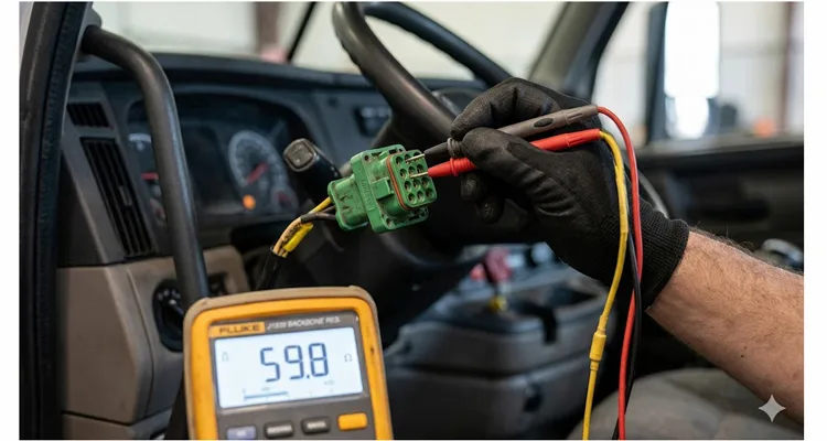
Minute 4–6: Resistance Test at the Diagnostic Connector
This single test provides more value than any other step. It confirms the integrity of your termination in under 60 seconds.
- Set your multimeter to Ohms (Ω).
- Probe Pin C (CAN High) and Pin D (CAN Low) on the diagnostic connector.
- Observe the resistance value.
Interpreting the reading:
- 60 Ω (± 6 Ω): Both termination resistors are present and the backbone is electrically continuous. Move to the voltage test.
- 120 Ω: Only one terminating resistor is connected. The second is missing, corroded, or disconnected. Begin the hunt.
- Open circuit (infinite resistance): The backbone is physically severed somewhere, or both resistors are missing entirely.
- Near 0 Ω: A short circuit exists between CAN High and CAN Low. This will shut down all J1939 communication instantly.
I once spent two hours chasing a “no communication” complaint on a Freightliner Century Class, only to discover the previous shop had removed the rear terminating resistor to install an aftermarket telematics device and never reinstalled it. A 120 Ω reading at the diagnostic connector pointed directly to the missing termination in about 30 seconds.
Minute 7–10: Isolate Individual Terminating Resistors
If your resistance reading was 120 Ω instead of 60 Ω, you must locate the missing resistor. Here’s the reality of field work: terminating resistors are not always obvious. On some platforms, one resistor is embedded within the engine ECM connector body. On others, you’ll find a Deutsch connector cap with a resistor soldered across two pins, wrapped in heat‑shrink tubing and zip‑tied to a frame rail.
Common locations:
- Front resistor: Frequently near the in‑cab fuse block, or integrated into the engine ECM harness connector.
- Rear resistor: Typically located near the ABS ECU at the rear of the chassis, along the left frame rail, or adjacent to the transmission in the powertrain harness.
Once you locate a suspect resistor, disconnect it and measure directly across its pins. A functional resistor reads 120 Ω (± 10 Ω). An open reading indicates a failed component. Replace it with a 120 Ω, 1/4 W resistor and re‑verify the network resistance at the diagnostic connector.
Minute 11–15: Voltage Testing for Shorts to Ground or Power
Switch the ignition ON (engine not running). Now you’re checking for faults that resistance testing cannot expose.
- Set your multimeter to DC Volts.
- Measure between Pin A (Ground) and Pin C (CAN High).
- Measure between Pin A (Ground) and Pin D (CAN Low).
Expected result: Both measurements should rest at approximately 2.5 V. This is the recessive state voltage.
Interpreting deviations:
- Both pins read 0 V: The J1939 network is shorted to ground. This is commonly caused by chafed insulation where the harness rubs against a sharp metal edge.But a short to ground isn’t always visible from the outside—we’ve cut open cables where water had wicked 18 inches up the jacket from a hairline split, turning the shield braid into rust wool. Our deep dive on J1939 cable shield and jacket failures shows exactly how environmental ingress kills a backbone from the inside out.
- One pin reads battery voltage (12 V or 24 V): The network is shorted to power. Inspect areas where wiring passes near power distribution points for pinched or melted insulation.
- Both pins read exactly the same voltage (not 2.5 V): CAN High and CAN Low are shorted together. This corresponds to the near‑0 Ω resistance reading you would have observed earlier.
- CAN High reads 2.5 V, CAN Low reads 0 V: CAN Low is shorted to ground.
Cummins diagnostic procedures reinforce a similar guideline: a voltage below 1 V suggests a short to ground; a voltage above 11 V suggests a short to power.
Minute 16–20: Physical Inspection and the Wiggle Test
This is where you rely on your eyes and your hands. Electrical faults are seldom considerate enough to appear on a meter when the vehicle is stationary in the shop. Intermittent failures—the ones that only surface when the chassis flexes or the engine torques—are almost always mechanical in origin.
- Visually trace the backbone. Follow the twisted yellow and green pair along the frame rail. Look for areas where the harness contacts metal edges or passes through bulkheads without a protective grommet.
- Inspect every accessible Deutsch connector along the J1939 backbone. Look for:
- Green or white corrosion deposits on the pins.
- Terminals that are pushed back, bent, or spread open.
- Evidence of water intrusion or debris inside the connector cavity.
- Execute the wiggle test. With your meter still connected and monitoring voltage, have a second person gently manipulate the harness at various points. Any sudden jump or dropout in the voltage reading pinpoints the trouble spot.
I once diagnosed a school bus J1939 fault where the resistance measured 118 Ω—just enough deviation from 60 Ω to kill communication entirely. The culprit was a corroded connector leading to the rear terminating resistor. The connector had been wrapped in electrical tape and tucked against the main harness near the ABS module. Several winters of moisture intrusion had slowly consumed the terminal pins.
Five Common Mistakes That Turn a 20‑Minute Job into a Two‑Day Nightmare
Mistake #1: Leaving the Ignition On During Resistance Testing
This will produce wildly inaccurate resistance values and, in the worst case, damage your meter. Always verify key OFF and battery disconnect OFF.
Mistake #2: Assuming All 60 Ω Readings Mean the Network Is Healthy
I’ve encountered networks that displayed a perfect 60 Ω at the diagnostic connector yet failed intermittently under load. A partially corroded connector or a wire with fractured strands inside the insulation can pass a static resistance test while failing completely under vibration or thermal expansion.
Mistake #3: Treating Termination Like a ‘More is Better’ Situation
I once approached a combine that had three—three—120‑ohm resistors daisy‑chained at the rear bulkhead because a well‑meaning technician believed he could ‘strengthen the signal.’ The resistance at the diagnostic port measured a solid 40 ohms. The machine operated in this state for nearly a week before the ABS module flagged a permanent internal hardware fault (SPN 629 FMI 12). A $3 resistor error became a $1,200 ABS ECU replacement. On a heavy‑duty backbone, the rule is absolute: exactly two termination resistors, no more, no less.Termination errors don’t stop at resistance readings—combined with improper stub lengths, they create phantom faults that cost fleets over $4,000 a year in misdirected diagnostics.
Mistake #4: Neglecting to Check the Diagnostic Connector Pins Themselves
A bent or corroded Pin C or Pin D at the 9‑pin connector will sabotage every measurement you take. I keep a compact inspection mirror and a dedicated flashlight in my kit specifically for examining these terminals.
Mistake #5: Replacing an ECU Before Verifying the Physical Layer
This is the expensive mistake that keeps parts counters in business. I’ve lost count of how many times I’ve seen technicians condemn a perfectly functional engine ECM or ABS module based solely on a “no communication” symptom. A $3 terminating resistor or a $0.50 butt connector is almost always the true culprit. Before you authorize an ECU replacement, confirm the physical layer is intact—otherwise you’re gambling with your shop’s reputation and your customer’s wallet.
How to Confirm You’ve Fixed the J1939 Data Link Problem
After completing your repair—whether it involved replacing a resistor, cleaning a corroded connector, or repairing a chafed wire—follow this validation sequence:
Step 1: Re‑Measure Resistance
Key OFF. Confirm 60 Ω (± 6 Ω) at the diagnostic connector.
Step 2: Re‑Measure Voltages
Key ON. Confirm approximately 2.5 V on both CAN High and CAN Low relative to ground.
Step 3: Connect Your Scan Tool
Establish stable communication and verify that you can retrieve data from all expected ECUs (engine, transmission, ABS, instrument cluster).
Step 4: Clear All Fault Codes
Step 5: Perform a Road Test
This step is critical for confirming the repair of intermittent faults. Operate the vehicle under normal driving conditions and monitor for any return of J1939 communication errors.
If the fault resurfaces after completing this sequence, you’re likely facing an upstream issue—perhaps a failing ECU that’s pulling down the entire network, or an improperly spliced aftermarket device. At that stage, you’ll need to isolate devices one by one. However, for over 90% of the J1939 data link failures I encounter in the field, the 20‑minute checklist above has already identified and resolved the problem.
Related Diagnostic Products from Our Factory Floor
While a multimeter handles the diagnostic heavy lifting described above, some jobs demand specialized hardware. At OBD‑Cable, we manufacture the cables and connectors that professionals rely on for heavy‑duty diagnostics.
Our J1939 diagnostic cables are engineered to SAE J1939/11 and J1939/13 standards, utilizing RoHS‑compliant materials and undergoing 100% shielding integrity testing. Whether your application calls for a standard 9‑pin Deutsch to 16‑pin OBD2 adapter, a durable Y‑splitter for fleet telematics deployments, or a fully custom cable assembly built to your exact specifications—including custom branding, length, and color—we can produce it.
For shops that regularly work on mixed fleets, our J1939 9‑Pin Female to DT 12‑Pin Male Adapter Cable bridges the gap between standard diagnostic tools and vehicles equipped with DT‑series connectors, such as certain Volvo, Scania, and Freightliner models.
When you need to access CAN High and CAN Low signals for voltage testing without back‑probing, a J1939 9‑Pin Pigtail Breakout Cable gives you clean access to both Type 1 and Type 2 ports. The open‑wire design makes it easy to route through tight dash panels and connect multiple diagnostic tools simultaneously—exactly what you want when you’re performing the wiggle test or logging data from more than one module.
Every cable assembly passes through a 4‑step quality inspection protocol within our climate‑controlled facility before it leaves the production floor. With over 20 years of direct factory experience, we supply distributors and OEMs across North America, Europe, and Australia.
Our manufacturing operations are certified to ISO 9001 quality management and ISO 14001 environmental management standards, and we hold IATF 16949 automotive quality certification—the global benchmark for automotive series production.
If you’re weary of diagnostic cables that fail after six months of field use, let’s discuss building a solution that lasts.
Explore our range of heavy‑duty diagnostic cables to ensure your fleet maintains reliable J1939 communication.
Frequently Asked Questions
Q1: Can a J1939 network function with only one terminating resistor?
It may function intermittently, but it will never be reliable. The termination resistors suppress signal reflections that corrupt data transmission. With only one resistor, expect erratic J1939 communication, dropped messages, and random fault codes.
Q2: What gauge wire is used for J1939 backbones?
The SAE J1939 standard specifies 18 AWG to 22 AWG twisted‑pair cable. The twist rate should maintain a minimum of 33 twists per meter to preserve noise immunity.
Q3: How do I tell CAN High from CAN Low if the colors have faded?
CAN High is typically yellow. CAN Low is typically green. If the insulation colors are indistinguishable, rely on your meter: with the key ON and the network idle, both should read approximately 2.5 V relative to ground. During active J1939 communication, the wire that swings higher (toward 3.5 V) is CAN High, and the wire that swings lower (toward 1.5 V) is CAN Low.
Q4: Can a bad ground cause J1939 communication failures?
Absolutely. Every ECU on the J1939 network requires a solid ground reference. A loose or corroded ground connection at a single module can cause that ECU to drop off the backbone, even if the J1939 wiring itself is fault‑free.
Q5: What’s the difference between J1939/11 and J1939/15?
J1939/11 defines a shielded twisted‑pair cable for maximum EMI immunity. J1939/15 refers to the unshielded variant. In practice, most heavy‑duty applications deploy J1939/11 cabling to withstand harsh electrical environments.
Q6: How many ECUs can be on a single J1939 network?
The SAE J1939 specification supports up to 30 nodes (ECUs) on a single backbone.
Q7: Can I use a standard OBD2 scan tool on a J1939 vehicle?
Only with a proper J1939 to OBD2 adapter cable. The physical connectors and communication protocols differ entirely. A 9‑pin Deutsch to 16‑pin OBD2 adapter is required to interface the two systems correctly.
Q8: Why does my scan tool connect sometimes but not others?
This is the classic fingerprint of an intermittent physical layer fault. Look for loose Deutsch connectors, corroded terminals, or a harness section that shifts when the engine torques under load. The wiggle test described earlier is the most effective method for isolating these failures.
Q9: What fault code typically indicates a J1939 data link problem?
SPN 639 (J1939 Network #1) accompanied by FMI 9 (Abnormal Update Rate) or FMI 14 (Special Instruction) is the most prevalent indicator. You may also encounter transmission‑specific code 35 on certain platforms.
Q10: Do I need an oscilloscope to diagnose J1939 problems?
For 90% of J1939 data link failures, a multimeter and the checklist above are entirely sufficient to locate the issue. An oscilloscope becomes valuable when you suspect an ECU is flooding the bus with erroneous messages or when you’re confronting a complex, elusive intermittent fault that resists all other diagnostic methods.
Need Something More Than a Checklist?
You’ve now got the diagnostic framework. Ensure your tooling is equally prepared for the task.
We operate as a direct factory facility, certified to ISO 9001, ISO 14001, and IATF 16949 standards. We specialize in OEM and custom diagnostic cable assemblies—no minimum order quantity for prototype samples, and full engineering support from initial concept through final production.
📱 WhatsApp (Linda): +86 173 0716 8662
📧 Contact Page: obd-cable.com/contact
Whether you require a single prototype to validate a new fleet deployment or a full production run with custom branding and specifications, reach out. We’ll build precisely what your operation demands and stand behind every cable we ship.
