

Estimated reading time: 18 minutes
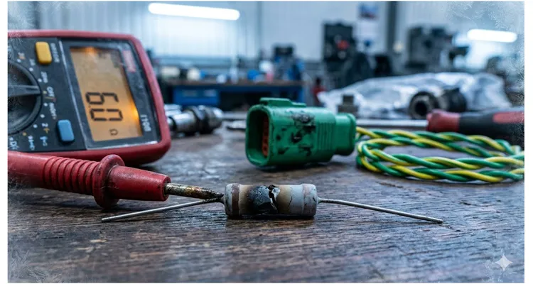
I keep a specific 120-ohm resistor in my desk drawer. Not for use—it’s burned open. I pulled it from a 2022 refuse truck that had logged 47 distinct J1939 Data Link Error events in a single winter. The fleet had already swapped the entire chassis harness ($2,100 in parts) before I ever opened the diagnostic connector.
Here’s what the diagnostic trouble code (DTC) printout fails to reveal: The SAE J1939/11 standard is written for linear time-invariant conditions on a lab bench. Your truck on a cold start in Iowa operates as a time-variant system. When the stub length tables were drafted, nobody envisioned a telematics installer grabbing 75°C-rated PVC zip cord and running it as a drop line inside a -20°C wheel well.
That charred resistor sitting on my desk marks the boundary between textbook J1939 compliance and a recurring $4,000/year phantom fault. Let’s examine the impedance cliff edge the spec sheet omits. If your fleet is sourcing J1939 cable assemblies, grasping this edge isn’t optional. We’ve cataloged this precise failure signature in our J1939 phantom fault cost analysis, extracted from two decades of factory forensic work. For broader context on the protocol architecture, SAE J1939 is the vehicle bus recommended practice that defines communication and diagnostics among vehicle components across the commercial vehicle industry.
The 2-µs Cliff: Why Time Matters More Than Voltage
Set voltage aside. Focus on time.
At 250 kbps, a single bit width occupies 4 microseconds (µs). A signal traveling through standard PVC-jacketed twisted pair experiences a propagation delay near 5 nanoseconds per meter (ns/m).
Take a 4.2-meter stub—identical to the one on the truck that supplied my burned resistor. The signal races down that dead-end conductor, hits the open circuit, and reflects. Round trip: 8.4 meters. Delay: 42 nanoseconds.
Insignificant? Hardly.
When that 42 ns reflection slams back into the main trunk exactly as the adjacent ECU attempts to drive a dominant bit, the CAN controller confronts a superposition—a voltage level hovering between recessive and cleanly dominant. The transceiver slips into bit sampling uncertainty. On the bench, it’s noise. Bouncing across a rumble strip, it’s a Bus-Off event.
This “bit sampling uncertainty” is exactly what we dissect in granular detail in our follow-up investigation: J1939 Bit Sampling Errors: The $4,000/Year Phantom Fault You’re Chasing with Software Updates. That article explains why your scope shows a clean waveform yet the ECU still misreads the bit—and provides a 5-step diagnostic method that doesn’t require a $15,000 Vector toolchain.
This explains why the 1-meter stub rule isn’t guidance. At 1 meter, the reflection returns in 10 ns—safely ahead of the sample point. It dissipates. At 4 meters, the reflection coincides with the sample point. You’ve armed a thermal- and vibration-triggered time bomb.
Termination: The Impedance Anchor You Can’t Skip
Among all the J1939 physical layer fault scenarios I chase in the field, incorrect termination resistance tops the list. J1939 mandates exactly two 120-ohm resistors—one at each physical extremity of the backbone. They bridge CAN_H (yellow) and CAN_L (green). With both resistors present and the network unpowered, expect roughly 60 ohms across CAN_H and CAN_L. Our J1939 backbone termination and stub length guide expands on the full architecture.
The “Missing Resistor” Problem
A backbone equipped with a solitary terminator registers 120 ohms. Under pristine conditions—minimal traffic, abbreviated backbone, zero EMI—the network might limp along. Introduce vibration, thermal cycling, or elevated bus utilization, and missing termination unleashes reflections that masquerade as sporadic communication failures.
I’ve witnessed this after a technician swapped an ECU containing an internal terminator for a variant lacking one. The original network design relied on that internal resistance. No verification. Six months of intermittent faults ensued. This identical scenario appears in our J1939 termination mistakes and ECU repair cost analysis.
The “Extra Resistor” Problem
Installing a third terminator depresses impedance excessively, straining CAN transceivers and compressing signal amplitude. The network teeters on the edge—functional on the bench, unreliable across temperature swings. One memorable instance involved a generator set manufacturer who shipped units with termination resistors already resident on the engine ECM, the control panel, and a third plugged into the diagnostic connector. They couldn’t decipher why 15% of units bombed factory communication tests.
Measuring What Matters
Here’s the field test I perform without exception:
- Power down the vehicle completely. Battery disconnect recommended.
- Access the diagnostic connector (9-pin Deutsch, typically pin C = CAN_H, pin D = CAN_L).
- Measure resistance between CAN_H and CAN_L. Target: 60 Ω (± 5-10 Ω depending on cable length).
- If you observe 120 Ω: One terminator is missing.
- If you observe 40 Ω or less: Multiple terminators exist, or a partial short is present.
- If you observe open circuit: Both terminators are absent, or the backbone is severed.
This resistance check isolates 80% of faults. The remaining 20% call for the approach in our CAN bus physical layer testing guide. When you need to access individual CAN_H and CAN_L signals for benchtop analysis, a J1939 9-pin breakout cable eliminates the frustration of back-probing connector pins.
Stub Lengths: The Harmonic Trap (Not Just a DC Short)
RF engineering recognizes the quarter-wave stub phenomenon. At a particular length relative to the signal wavelength, an unterminated stub stops merely reflecting—it transforms into a dead short at the tap point.
Could a 4-meter J1939 stub behave as a quarter-wave stub? Let’s calculate. Wavelength (λ) = Velocity / Frequency. At 250 kbps (fundamental frequency near 125 kHz for a square wave), the wavelength stretches beyond a kilometer. Textbook RF principles label a 4-meter stub “electrically short.”
That’s the deception.
J1939 signals aren’t sinusoidal. They’re square waves laden with harmonics. The fast rising edge packs frequency components well into the MHz region. At 6.25 MHz (a prominent harmonic of 250 kbps), a 4-meter stub approaches 1/10th wavelength. That’s ample length to inject phase shift capable of corrupting the arbitration field—the portion of the message determining bus priority.
I’ve captured this on a scope. The voltage at the stub junction doesn’t merely sag; it displays a pronounced shelf during the identifier bits. The ECU hanging off that 4-meter stub perceives a divergent bus state from the rest of the network. It forfeits arbitration whenever contention arises. Hence the intermittent nature of the fault. It surfaces only when two high-priority messages—say, Engine Speed and Transmission Output Speed—contend for the bus within the same microsecond.
The Aftermarket Telematics Problem
The predominant source of excessive stub length I encounter stems from aftermarket telematics and ELD retrofits. A technician locates a convenient access point on the J1939 backbone—frequently adjacent to the diagnostic connector—and routes a lengthy cable to a telematics module mounted across the cab.
The proper remedy: position the telematics unit within 1 meter of the tap point, or extend the backbone so the telematics module occupies a physical end position with proper termination. Fleets demanding compliant J1939 harness manufacturing can sidestep this variable altogether with pre-terminated backbone extensions. In confined chassis routes where a straight connector won’t clear, a 90-degree right-angle J1939 Y-splitter preserves topology without kinking the twisted pair.
Wiring Practices That Compound the Damage
Splice Quality & Fretting Corrosion
Every splice introduced into a CAN network creates an impedance change. A genuine Deutsch or Amphenol Y-splitter maintains impedance control; a random butt splice does not. Worse, corrosion at splice junctions adds resistance that erodes signal amplitude. A fresh splice measuring 0.1 Ω can degrade to 5–10 Ω after two winters of road salt exposure. In a CAN network where termination resistance tolerances are narrow, this shift matters. Consult our Deutsch DT and HD connector guide for connector selection details.
Shield Grounding Errors
J1939/11 mandates shielded twisted pair. The shield must be grounded at exactly one location to suppress ground loops. I regularly uncover shields bonded at both ends, or left floating entirely. A shield grounded at both ends furnishes a low-impedance conduit for current circulating between disparate ground potentials. That current injects noise straight onto the signal pair.
What This Actually Costs
A lone incorrectly terminated J1939 network can trigger 3–5 service visits annually before anyone pinpoints the root cause. At $500–$1,000 per visit in direct expenses, the tally reaches $1,500–$5,000 annually—per vehicle.
Direct costs per incident:
- Tow to service facility: $350–$800
- Diagnostic labor (2–4 hours): $250–$660
- Parts replaced unnecessarily (sensors, ECUs, harness sections): $200–$2,000
Indirect costs:
- Lost revenue from idle equipment: $800–$1,500/day
- Missed delivery windows and contract penalties
I’ve observed fleets replace ECUs, instrument clusters, and complete engine harnesses while pursuing “J1939 communication errors” whose true origin was a missing terminator or a 15-foot stub installed three years prior. Before ordering another high-dollar module, validate the physical layer with reliable OBD diagnostic tools and a multimeter. Uncertain whether to grab a meter or a scope first? Our multimeter vs. oscilloscope guide for CAN bus diagnostics offers clarity.
A Systematic Approach to Diagnosis
Step 1: Resistance Check (Power Off)
Measure CAN_H to CAN_L resistance at the diagnostic connector.
- 60 Ω ± 10%: Terminators accounted for.
- 120 Ω: One terminator absent.
- 40 Ω or less: Extra terminator(s) or partial short.
Step 2: Voltage Check (Power On, Network Idle)
- CAN_H: 2.5–3.5 V (recessive)
- CAN_L: 1.5–2.5 V (recessive)
- Differential: ~0 V recessive, ~2 V dominant
For the full voltage profile under load and battery extremes, see our J1939 CAN High and CAN Low normal voltage range reference.
Step 3: Physical Inspection
Search for stubs exceeding 1 meter (J1939/11) or 3 meters (J1939/15), aftermarket splices, damaged twisted pair, and corroded Deutsch connectors.
Step 4: Scope the Signals (When Necessary)
I rely on a PicoScope with J1939 decoding. Hunt for reflections—stair-stepping or ringing along waveform edges. The timing of those reflections discloses exactly how far down the backbone the trouble resides. A rapid J1939 voltage drop field test can also flag high-resistance connections before the scope even powers up.
Common Questions I Hear in the Field
Q: Why does my J1939 link fail only above 1,500 RPM?
| Scenario | Diagnostic Signature (Ohms) | Diagnostic Signature (Scope) | The Likely Physical Culprit |
|---|---|---|---|
| Intermittent Derate @ 1,500 RPM | 60 Ω static (normal) | Differential Voltage drops from 2.0V to 0.7V | Fretting Corrosion inside a Deutsch DT connector. Vibration at resonance fractures the tin-lead oxide layer. |
| Fail @ 1,500 RPM | 120 Ω (bad) | Overshoot spikes on CAN_H | Missing termination combined with high alternator ripple. The un-terminated bus behaves as an antenna. |
| Fail @ Idle, OK @ High RPM | 60 Ω | Error frames coincide with injector firing | Shield grounded at both ends. High-current injector pulses generate ground loop current. |
Q: Can I use a single 60-ohm resistor instead of two 120-ohm resistors?
No. A solitary 60-ohm resistor positioned anywhere except the electrical midpoint produces asymmetric termination. The impedance observed from one direction diverges from the other. Reflections result.
Q: What happens if I accidentally install three terminators?
Parallel resistance plummets to 40 Ω. This overworks CAN transceivers and compresses signal amplitude. The network may falter intermittently, particularly in cold conditions or under heavy traffic. Prolonged exposure risks transceiver damage.
Q: How do I properly terminate a backbone when I add a device at the end?
Extract the existing terminator from the backbone endpoint. Attach the new device via a short stub (under 1 meter). Place the terminator at the device connector or directly adjacent to it.
Q: Is there a quick way to check if stub length is my problem?
Unplug the suspect stub at the backbone junction. Network stabilization confirms the diagnosis.
Why Factory Crimping Matters on a 60-Ohm Network
That “burned resistor” from the Iowa truck? The root cause wasn’t the resistor body. It was cold flow of PVC insulation inside a hand-crimped butt connector.
Within our climate-controlled warehouse (maintained at 45-55% RH to forestall copper oxidation prior to crimping), every J1939 backbone assembly endures 4-point pull testing on a Mark-10 motorized stand. Why? Because the gap between a 0.1Ω connection and a 5.0Ω connection on a stub equates to the difference between a crisp dominant bit and “bit sampling error.”
When we fulfill custom OEM orders—logo branding, exact Deutsch pin-outs, color-coded AWG matching your chassis schematic—we aren’t merely trimming wire. We confirm characteristic impedance of the twisted pair holds at 120Ω ± 5% across the entire reel using an automated LCR bridge.
Our facility operates under ISO 9001, ISO 14001, and IATF 16949 quality frameworks, with RoHS, CE, UL, and REACH compliance spanning our product range. Review our IATF 16949:2016 certification milestone and ISO 14001:2015 environmental management certificate for complete transparency. Every cable passes through a 4-step quality inspection before departing our 5S-managed warehouse. That’s what constitutes dependable J1939 cable manufacturing at production volume.
If you’re developing a new telematics harness or require a 100% RoHS compliant, REACH-verified backbone for a Tier 1 supplier audit, reach out through the links below. Request an Impedance Trace Report alongside your quotation. We’ll supply the waveform data before the cable leaves our dock.
Connect via WhatsApp to discuss your application directly with our engineering team, or visit our OEM custom cable contact page to submit a comprehensive inquiry. No automated replies. No boilerplate estimates. Straight dialogue with individuals who comprehend J1939 down to the physical layer.
Contact Page: https://obd-cable.com/contact/
