

If you’ve ever logged hours chasing intermittent CAN bus faults across a piece of yellow iron or a fleet truck, you’ve learned one brutal lesson: the connector is seldom the first place anyone investigates. It’s the last refuge of a tired diagnostic routine. Only after you’ve rotated the ECU, shaken the harness while staring at a scope, and metered the termination resistor five separate times do you finally crack open a Deutsch connector, spot the verdigris blooming on pin C, and realize the customer just paid for three hours of labor to correct a problem that demanded thirty seconds of actual work.
This isn’t a classroom dissertation on SAE J1939. It’s field wisdom on the three Deutsch series that genuinely matter when you’re standing in slop or facing a blank diagnostic interface—DT, HD10, and HD30. Grasping where one series ends and another begins is what separates a properly specified harness from a truck that sporadically drops its transmission controller every time the humidity climbs.
Spec sheets serve their purpose when you’re ordering inventory from a clean office. The following pages contain the kind of knowledge you reach for when the iron is down and the shop manual is three buildings away.
The Misconception About “The J1939 Connector“
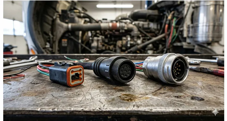
I keep running into the same flawed premise in fleet bulletins and shop-talk forums—the notion that the term “J1939 connector” describes a single, universally applicable component. It doesn’t. SAE J1939 is the vehicle bus recommended practice used for communication and diagnostics among vehicle components throughout the commercial vehicle area, and its physical layer borrows heavily from ISO 11898. The standard family actually parcels out several physical layer implementations, each with its own distinct connector requirements. SAE J1939/11 operates over a 3-wire system and relies on Deutsch DT series connectors for the primary backbone communication on trucks and buses. SAE J1939/13 details the off-board diagnostic connector, which takes shape as the Deutsch HD10-9-1939—a 9-pin round connector. SAE J1939/15 switches to a 2-wire system and specifies Deutsch DTM series connectors.
Strip away the jargon and there’s no catch-all “J1939 connector.” What exists is a family of Deutsch products, each assigned to a particular function inside the network architecture. Recognizing which connector type belongs at which junction is what distinguishes a robust installation from a chassis that decides to abandon communication with its transmission controller the moment the pavement gets damp. Before we break down the individual series, make sure you’re solid on J1939 wiring diagram basics and CAN high/low identification; crossed pins are the starting point for more diagnostic dead ends than any other single mistake.
DT Series: The Backbone You Don’t Notice (Until It Fails)
The DT series encompasses the rectangular connector system you’ll encounter on engine ECM pigtails, transmission controllers, and practically every in-line junction scattered across the chassis. DEUTSCH DT connectors are designed for high-performance and reliable connections in industrial and commercial transportation applications—under hoods, along frame rails, and inside cabs—with a V0-recognized thermoplastic housing that tolerates a broad operating temperature window and shrugs off UV exposure. SAE J1939/11 designates these 3-wire DT connectors explicitly for backbone communication among ECUs across a truck or bus platform. They utilize size 16 contacts and handle 14-20 AWG wire comfortably. Contact rating lands at 13 amps continuous, which offers plenty of overhead for CAN signals, yet the real headline is how they endure mechanically across tens of thousands of operating hours.
I’ve pulled apart DT connectors harvested from machinery that had accumulated over 8,000 hours in limestone dust and quarry washdowns. The housing plastic had faded to chalk, the wedgelocks had stiffened to the point of stubbornness, but the silicone seals remained intact and pliable. That’s the payoff from a correctly assembled DT connection: the interface seal and the rear wire seal acting in tandem to exclude grit and moisture from the contact cavity. If you’re trying to balance Deutsch connector series selection with maintenance budget impact across a mixed fleet, this is precisely the sort of long-haul durability that justifies the initial acquisition cost.
One detail the product literature consistently underplays: the wedgelock is not window dressing. It serves as the secondary locking mechanism that prevents terminals from backing out under sustained vibration. I recall an entire afternoon lost to a “intermittent J1939 communication” fault on a concrete pump truck that traced back to a missing wedgelock on the transmission ECU connector. The affected terminal had drifted rearward maybe half a millimeter—barely enough to lift contact when the engine twisted under load. That wedgelock costs pocket change. Leaving it out costs diagnostic hours you’ll never recover. This is exactly the kind of mechanical oversight that masquerades as a J1939 network calibration issue that no amount of parameter flashing will remedy.
Another observation worth storing: DT connectors depend on a latch-style locking mechanism. The latch stays put, but it requires a purposeful release action. When you’re wedged into a tight spot with numbed fingers, that latch will try your temperament. Yet the very same stubbornness guarantees the connector isn’t going to vibrate apart at highway speeds. And when you’re routing a harness through a confined area where a straight-bodied connector simply won’t clear a bracket or crossmember, a J1939 90-degree right-angle Deutsch DT cable resolves the clearance conflict without sacrificing sealing integrity or terminal retention.
HD10 Series: The Diagnostic Gateway and Chassis Workhorse
The HD10 is a cylindrical connector system, fully environmentally sealed, built around thermoplastic housings and available with cavity arrangements from 3 up to 9 positions. In J1939 applications, the configuration you’ll encounter repeatedly is the 9-pin diagnostic connector spelled out in SAE J1939/13—formally referred to as HD10-9-1939.
If you’ve ever attached a scan tool to a Kenworth or a John Deere tractor, you’ve already mated with an HD10 interface. Instead of reproducing a pinout chart that reads like a page lifted from a TE Connectivity catalog, let’s walk the pin assignments with the sort of commentary that only comes from chasing field failures.
Pin C and D constitute the CAN differential pair. A 60Ω reading across this pair confirms that the backbone remains intact before you ever boot up a scan tool. Should that resistance value drift, you’re looking at a J1939 voltage drop scenario that merits deeper investigation before you point a finger at any ECU. Pin A serves as chassis ground, but here’s a hard-won observation: on a specific run of Mack trucks manufactured between 2015 and 2018, the ground conductor inside the harness corrodes approximately three inches aft of the connector shell. You’ll ring out perfect continuity at the pin face, yet the circuit collapses under actual electrical load. The symptom set mimics a failed ECU, but it’s merely concealed wire degradation.
Pin E functions as the shield drain. This is the pin technicians routinely overlook. Leave it unterminated and floating, and you’ve effectively erected an antenna tuned to every VGT actuator and injector solenoid firing on the engine harness. In a high-noise engine bay, properly landing that shield is what separates clean data packets from a bus awash in error frames. Our detailed analysis of J1939 cable shield impedance and jacket specifications demonstrates why economizing on the shield is a false savings.
Pins F and G carry the legacy J1708 databus signals. Even if your operation is exclusively J1939, don’t assume these lines are dormant. On mixed fleets with older trailers or third-party body controllers, these pins remain active and can pull down the voltage reference if they develop a short to ground. Fleets that disregard J1708 diagnostics in legacy support frequently find themselves chasing faults that a basic pin inspection would have uncovered.
Pins H and J occupy OEM-specific territory. On certain equipment, these pins transport a secondary CAN channel for implement communications. On other machines, they’re entirely unpopulated. I maintain a running notepad entry titled “OEM Pin H/J Exceptions” because assuming continuity on these pins without verifying the schematic is the quickest path to damaging a scan tool interface.
The Green vs. Black 9-Pin Deutsch Connector Distinction
Beginning around the 2016 model year, new trucks started arriving with green 9-pin diagnostic connectors replacing the long-familiar black ones. This shift was not an aesthetic choice. The green Type II connector accommodates dual CAN channels and supports data rates up to 1 Mbps, whereas the black Type I variant is limited to a single channel. A black cable cannot be forced into a green diagnostic port—the keying deliberately blocks insertion. Earlier adapters and scan tools were never designed for 500 Kbps communication, and jamming a connection could damage the tool, the vehicle network, or both. If your fleet spans both sides of this model-year divide, your cable inventory must support both connector styles. For a side-by-side comparison, consult our J1939 Type 1 vs Type 2 guide and the practical advice on choosing a J1939 Type 1 to Type 2 adapter. Misreading which type is installed on a truck is a textbook J1939 Type1/Type2 misdiagnosis that costs shops thousands in squandered hours.
HD30 Series: When the Environment Fights Back
The HD30 series occupies the rugged end of the Deutsch family. Whereas DT and HD10 employ thermoplastic housings, HD30 connectors transition to aluminum shells and incorporate bayonet coupling, single-hole bulkhead mounting, silicone seals, and a rear insertion/removal contact system. You specify HD30 for connections that face direct road spray, accumulated mud, or persistent mechanical contact—think engine bay bulkhead pass-throughs, transmission bellhousing interfaces, and undercarriage junction boxes.
Current-handling capability escalates considerably: HD30 accepts contact sizes ranging from size 4 (100 amps) down through size 8 (60 amps), size 12 (25 amps), size 16 (13 amps), and size 20 (7.5 amps). As a result, a single HD30 shell can route both high-current power and CAN signal lines simultaneously, which simplifies harness routing and trims branch points. Cavity arrangements run from as few as 2 positions up to 47.
In the field, the bayonet coupling is the feature that truly distinguishes this series. It engages with a quarter-turn and an audible click. No wedgelock to forget, no plastic latch to fracture. The trade-off resides in weight and unit cost—HD30 uses aluminum rather than injection-molded plastic, and the price per connector reflects that material choice. For a diagnostic port that sees action twice a year, it’s over-engineering. For an engine-bulkhead connection that absorbs every weather extreme the machine will ever encounter, it’s inexpensive reliability insurance. This is the same rationale we apply when specifying J1939 cables for agricultural survival in combine harvesters and self-propelled sprayers.
Another practical advantage: the rear insertion/removal contact system on HD30 enables you to service individual terminals without tearing down the entire connector shell. If you’ve ever faced the prospect of replacing a single damaged pin inside a fully sealed connector, you’ll appreciate the hours this design spares you.
A Decision Framework for the Field (Not a Spec Chart)
Push the catalog aside for a moment. When you’re standing next to a downed machine trying to determine which connector belongs where, ask these three questions:
- Is this connection exposed to direct road spray or wash-down pressure?
- Does it carry more than 15 amps?
- Will a technician need to disconnect it more than twice a year?
If road spray is part of the operating environment, eliminate DT from consideration. The rectangular latch seal on DT is capable, but it’s not “three winters of brine and a pressure washer” capable. That scenario falls squarely in HD30 territory—aluminum shell, bayonet lock, and seals that remain functional when the wash crew arrives.
If the circuit draws more than 15 amps, cross off DT and HD10 alike. HD30 accepts size 4 contacts rated for 100A. Attempting to force 25A through a size 16 contact is a recipe for softening and eventually melting connector bodies.
If the connection point is unplugged routinely—diagnostic port, implement interface—then HD10 fitted with a coupling ring surpasses the alternatives for one-handed operation in cold weather. The DT latch requires two hands and a focused release; the HD30 bayonet stays secure but isn’t intended for rapid disconnect. The HD10 coupling ring lands precisely in the sweet spot for service loops.
Four Failure Modes That Keep Repeating
Corrosion and Water Ingress
This failure mode sits atop the list. I first encountered this exact pattern on a Gillig Low Floor running Minneapolis routes in February 2014. That bus would lose communication with the transmission ECU at the identical intersection each morning—the one where plow crews had left a three-foot berm of salty slush that the front tire launched directly onto the chassis harness connector. NHTSA eventually flagged 2,200 units for the same overmold defect under recall 14V-123, but the field pattern was unmistakable months earlier: moisture ingress combined with freeze-thaw cycling produces terminals that resemble artifacts pulled from a battery acid bath.
When you witness intermittent CAN faults that track with weather conditions—the truck runs flawlessly on dry days but throws J1939 errors during rain or following a wash—you’re almost certainly chasing moisture ingress at a connector. Begin your search with any connector mounted low on the frame rail or oriented to catch frontal road spray. This is also the reasoning behind our emphasis on port environment analysis in cable failure investigations.
Terminal Damage and Backout
This failure surfaces most frequently after harness repairs conducted without the proper Deutsch extraction tools. The terminals are engineered to click positively into the housing, and the wedgelock provides secondary retention. If someone extracts a terminal using pliers or a sharp pick, the retention fingers deform. The terminal may feel seated upon reinsertion, but it isn’t.
On Peterbilt trucks equipped with green 9-pin Deutsch connectors, there are documented instances of installation-related communication faults originating specifically at the connector interface—some requiring adapter harnesses to remedy. The factory-installed connectors perform properly; the complications begin when aftermarket telematics devices are spliced inline without appropriate terminal preparation and tooling. A seemingly minor misstep here can cascade into a heavy-duty 9-pin connector diagnostic nightmare costing thousands in misdirected labor.
Series Mismatch
This seems too elementary to occur, yet it crops up more frequently than expected. DT and HD10 connectors are not interchangeable, even when the cavity counts align. The footprints differ, the sealing mechanisms differ, and the terminal retention method differs. I’ve encountered field-built adapters constructed from pigtails and heat-shrink tubing. They functioned adequately—right up until the first freeze-thaw cycle, at which point the heat-shrink lost its grip and the entire splice ingested water. If you must convert between series, use a proper bulkhead adapter or fabricate a custom harness with fully sealed junctions. Field splices on a CAN bus should remain the option of absolute last resort. For guidance on sidestepping the most frequent pitfalls when adapting between connector types, review our J1939 Type1 to Type2 adapter buyer’s guide. And when you genuinely need to bridge a 9-pin HD10 diagnostic port to a DT-series backbone connector for tooling or breakout work, a purpose-built J1939 9-pin female to DT 12-pin male adapter cable eliminates the guesswork and sealing compromises inherent in field splices.
Improper Wire Gauge Selection
DT and HD10 series both rely on size 16 contacts dimensioned for 14-20 AWG wire. If your application involves 22 AWG wire—typical on certain sensor leads—you need to shift to the DTM series, which employs size 20 contacts for 16-22 AWG. Attempting to crimp 22 AWG wire inside a size 16 contact will not yield a dependable termination. The crimp wings fail to fully engage the conductor strands, producing a high-resistance joint that passes bench testing but fails intermittently under vibration.
A subtler complication also exists: mismatched cables, tight bend radii, and poor cable design all affect impedance and J1939 performance. CAN bus operates on differential signaling over twisted pair. When assembling a replacement harness, maintain the original twist rate and preserve shield continuity through the connector body. Breaking the shield at the connector and hoping for the best creates an efficient receiving antenna for every alternator whine and ignition pulse within proximity. For a comprehensive methodology on verifying the physical layer, refer to our CAN bus physical layer testing guide.
Field Repair That Actually Works
Before you cut into any harness, measure the termination resistance. The J1939 control link should maintain a steady reading of 60 ohms—any deviation signals trouble in the circuit or a failed terminating resistor. A CAN bus missing one terminator will read 120 ohms; a short will pull the reading near zero. This measurement consumes thirty seconds and reveals whether the fault lies in the physical wiring or deeper within the network. Perform it first, not after you’ve already opened connectors. We’ve documented multiple cases where J1939 termination mistakes led directly to ECU repair costs that a simple resistance check would have averted.
Step 1: Extract the Terminals Properly
Acquire the correct removal tool—the DT-RT1 or a confirmed equivalent. Do not substitute a pick or a pocket screwdriver. The proper tool slips over the terminal from the front face and compresses the retention fingers, permitting the terminal to be drawn out from the rear. Prying with a pick damages the housing and deforms the retention features. A housing with compromised retention will never seal correctly again, and the terminal will gradually work its way loose.
Step 2: Inspect the Terminals and Contacts
Following extraction, examine the contact surfaces for corrosion, pitting, or mechanical galling. The mating area should appear clean and smooth. Green or white powder indicates active corrosion. Light oxidation can be addressed with electrical contact cleaner; heavy corrosion means the terminal is compromised and should be discarded. While you have access, inspect the seal. The silicone rear wire seal should remain pliable—not cracked, not hardened. A damaged seal allows moisture to wick along the wire directly into the connector body.
Step 3: Crimp Correctly or Don’t Bother
You can identify a substandard crimp before ever conducting a pull test. Roll the terminal between your thumb and forefinger. A proper Deutsch crimp feels uniform and machine-made—the indentations are crisp, the barrel compression even. A poor crimp feels lumpy; you can sense where the tool bottomed out inconsistently. Under magnification, you’ll observe that the conductor strands are crushed at the perimeter but remain loose in the center—a high-resistance joint waiting to manifest. The strain relief wings should grip the insulation without cutting through to the copper. If copper shows through the insulation crimp, you’ve over-crimped and introduced a stress riser that will eventually fracture, often around the 8,000-mile mark.
I keep a failed crimp cross-section in my toolbox, sectioned lengthwise with a Dremel. It illustrates what a proper cold-weld cross-section ought to resemble versus what emerges from a hardware-store crimper. That visual contrast is the difference between a connector that outlasts the machine and one that strands you on I-80 at two in the morning.
Step 4: Reassemble and Verify
Push the terminal forward until you hear the click. Seat the wedgelock fully. Reconnect the connector and verify communication before closing everything up. If you’re working on a diagnostic connector, a breakout box or CAN analyzer will confirm signal integrity. Lacking those tools, at a minimum ensure that your scan tool can establish communication and retrieve data from all expected ECUs. For a comparison of diagnostic approaches, our guide on CAN bus diagnostics: multimeter vs scope explains what each instrument reveals about connector health. If you need to monitor bus traffic while keeping the scan tool connected, a J1939 9-pin pigtail breakout cable provides safe access to CAN_H, CAN_L, and power without interrupting the diagnostic session.
Step 5: Verify the Termination Resistors
A correctly configured J1939 network requires 120-ohm resistors at each end of the backbone, yielding a parallel resistance of 60 ohms when measured across CAN_H and CAN_L. Missing resistors create an open circuit and disrupt communication; resistors that have drifted from their specified 120-ohm value degrade signal integrity. If you’ve repaired a connector and still encounter intermittent communication issues, recheck the terminator—it’s routinely overlooked and equally often the root cause. A J1939 phantom fault costing $4000 frequently traces back to a termination resistor that’s just enough out of specification to confuse the transceivers.
Common Errors That Cost Time and Money
- Using the wrong series for the application. DT is intended for the backbone, HD10 for the diagnostic port, HD30 for bulkheads exposed to weather and chemicals. Installing an HD10 where an HD30 belongs is comparable to painting an exterior wall with interior latex—it may look acceptable briefly, but it won’t survive the season.
- Skipping the wedgelock. The wedgelock supplies secondary terminal retention. Without it, terminals migrate under vibration. The initial symptom is usually “intermittent no-communication” that self-clears and then reappears. The wedgelock is the least expensive insurance you can apply to a J1939 harness.
- Reusing damaged seals. The silicone interface seal and rear wire seal are the sole barriers against water intrusion. If they are nicked, hardened, or permanently compressed, replace them. They are engineered as serviceable components for precisely this reason.
- Crimping without the proper Deutsch crimp tool. A generic automotive crimper cannot produce a dependable Deutsch connection. The terminal demands a specific indentation geometry to achieve the required contact pressure and mechanical retention. Employ the correct tooling or procure pre-assembled pigtails.
- Assuming all green 9-pin connectors are interchangeable. The green Type II connector utilizes different internal keying and pin assignments compared to the black Type I. A black cable will not seat, by design. Forcing it will damage the connector, the tool, or both. For fleets standardizing procurement, our J1939 cable TCO fleet procurement guide outlines how connector compatibility influences long-term ownership costs.
How to Verify the Repair Was Successful
After reassembly, clear all fault codes and operate the machine through its full performance envelope. Monitor for J1939 communication errors—active as well as pending. If you have access to a CAN analyzer, confirm that bus traffic remains consistent and error frames stay at zero. On a truck application, a road test with a scan tool observing all ECU communications will reveal whether the repair holds. Pay particular attention to the J1939 CAN high and CAN low battery normal voltage range during operation; voltage that sags under load frequently points to a ground issue concealed by a fresh connector assembly.
The genuine test is time and mileage. A connector assembled and sealed correctly should run tens of thousands of miles without recurrence. If the same fault reappears within a few weeks, you missed a contributing factor—likely moisture ingress past a compromised seal or a terminal that never fully seated.
Frequently Asked Questions
Q: What’s the actual difference between DT and HD10 connectors?
DT is rectangular and uses a latch lock for in-line backbone connections under SAE J1939/11. HD10 is cylindrical, available with or without a coupling ring, and serves diagnostic ports plus some chassis connections under SAE J1939/13. The contact systems share similarities, but the physical packaging and sealing methods differ.
Q: Can I use a black diagnostic cable on a green connector?
No. The green connector is keyed differently specifically to block insertion of older black cables. This protects the tool and the vehicle network from damage due to mismatched data rates.
Q: What AWG wire should I use for J1939 connections?
DT and HD10 accept 14-20 AWG wire with size 16 contacts. For lighter gauge (16-22 AWG), switch to DTM connectors. Wire gauge influences both current capacity and crimp reliability—match the gauge to the contact size.
Q: How do I know if my termination resistors are good?
Measure resistance between CAN_H and CAN_L with the network unpowered. Expect to see approximately 60 ohms. A reading of 120 ohms indicates one terminator is missing or open. A reading near zero indicates a short.
Q: Can I repair a Deutsch connector without special tools?
You can disassemble it, but you cannot reliably crimp new terminals without the proper Deutsch crimp tool. Reusing old terminals or crimping with pliers guarantees future failures.
Q: Why do J1939 connectors have a shield pin?
Pin E (CAN_SHLD) terminates the shield, protecting the CAN signals from electromagnetic interference. In high-noise settings—near alternators, inverters, or electric motors—a properly terminated shield is essential for reliable communication. For a comprehensive discussion, see our CAN bus shielding and filtering guide.
Q: What’s the difference between HD10 and HD30?
HD10 uses thermoplastic housings; HD30 uses aluminum shells with bayonet coupling. HD30 is engineered for more severe environments and higher pin counts, with contact sizes reaching size 4 (100 amps). HD10 is generally adequate for diagnostic ports and protected chassis connections.
Q: Are all Deutsch connectors compatible with J1939?
No. Although many Deutsch series appear in J1939 applications, the standard specifically calls for DT for /11 backbone connections, HD10 for /13 diagnostic connections, and DTM for /15 reduced physical layer applications. Other series like DTP or DTHD may be used elsewhere on the vehicle but fall outside the J1939 physical layer specifications.
Q: How often should J1939 connectors be inspected?
For heavy equipment operating in harsh conditions, inspect exposed connectors at least quarterly. Look for corrosion, damaged seals, loose mounting, or wire chafing at the backshell. Connector contacts should be cleaned periodically with anhydrous alcohol to remove oxide films and oil residues.
Q: What causes intermittent J1939 communication faults?
The leading causes include terminal fretting (micro-motion that oxidizes contact surfaces), moisture ingress leading to corrosion, loose connectors from missing or broken retention components, and damaged wiring adjacent to the connector backshell. Intermittent faults that align with temperature swings, humidity changes, or mechanical load are nearly always connector-related.
When Off-the-Shelf Isn’t Enough
Not every J1939 installation fits neatly into a standard catalog part number. I’ve worked on forestry equipment where off-the-shelf harness lengths came up short, mining trucks where the connector orientation fought the mounting bracket, and agricultural machines where the OEM color code failed to match our existing fleet inventory. In those situations, custom cable assemblies fabricated to your precise specifications make far more sense than attempting to piece together field modifications. This same principle applies whether you’re confronting a Freightliner RP1226 cable failure causing downtime or a specialized RP1226 Freightliner Cascadia telematics installation.
We’ve been manufacturing Deutsch-compatible harnesses for more than twenty years, and we’ve tackled enough unique applications to recognize that one size never genuinely fits all. Our production processes are supported by internationally recognized certifications, including ISO 14001:2015 environmental management and IATF 16949:2016 automotive quality management, ensuring that every assembly satisfies the rigorous standards demanded by OEMs and fleet operators alike. Whether the requirement is a non-standard length, a particular AWG, custom labeling, or a connector orientation that doesn’t appear in any catalog, we can build it. Each assembly undergoes 100% continuity and hipot testing before it leaves the production floor. We support fleets, equipment manufacturers, and aftermarket specialists who need reliable connectivity without the burden of maintaining an in-house harness shop.
If you’re contending with a recurring connector issue that shelf parts haven’t resolved, or if you’re engineering equipment that demands custom J1939 connectivity, get in touch. We’ll review your requirements and develop a practical solution—no sales pressure, just engineering support from people who work with these systems daily.
Contact our engineering team — or message us directly on WhatsApp and tell us about what you’re working on.
