

I’ve spent the better part of two decades in a factory that builds diagnostic cables—millions of them, shipped to workshops, equipment manufacturers, and fleet operators across sixty-odd countries. Over that time, one pattern repeats with almost comical regularity: a shop buys a five-figure scan tool, plugs it into a 2003 BMW or a 1999 Toyota, and gets… nothing. No communication. No DTCs. Just a blinking cursor and a sinking feeling in the technician’s stomach.
The problem isn’t the scan tool. It’s not the car, either—at least not in the way most people assume. The problem is the protocol sitting between them.
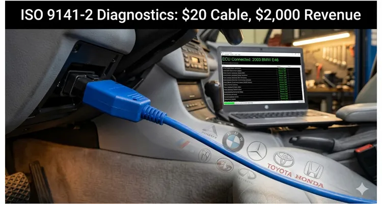
ISO 9141-2 is one of the five original OBD-II protocols mandated for emissions diagnostics. It’s the language spoken by most European and Asian vehicles built between roughly 1996 and the mid-2000s—Volkswagen, BMW, Mercedes-Benz, Audi, Honda, Toyota, Nissan, Mazda, and some Chrysler platforms. For a model-year-specific breakdown of BMW’s diagnostic protocols, see our guide on what OBD protocol BMW uses. If you’re working on a shop floor in 2026, these vehicles are now 20 to 30 years old. Their owners aren’t taking them to dealerships. They’re coming to independent shops. And when your $3,000 scan tool can’t talk to them, you’re turning away revenue.
A $20 K-Line cable solves that problem. But here’s the part most people miss: the cable isn’t just a wire. It’s a translator that has to survive automotive electrical environments while correctly implementing a handshake sequence that’s been widely misunderstood for three decades.
This article is about what actually happens on those two pins—and why getting it right matters more than most shops realize.
The Protocol That Won’t Die (And Why That’s Your Opportunity)
Here’s what twenty years on a factory floor teaches you about ISO 9141-2: the spec is frozen in time, but the cars it lives in are aging in unpredictable ways. The standard came out in 1994, Amendment 1 in 1996. It carves out a slice of the original ISO 9141:1989 document, restricting it to 12V systems and laying down the rules for how a scan tool talks to an emissions ECU under SAE J1978, the definitive standard that specifies the functional requirements for OBD-II scan tools.
If you pull the datasheet for the L9637D transceiver, you’ll find the baseline numbers: 10.4 kbaud signaling rate, a 510Ω pull-up to battery voltage on the K-line. What the datasheet won’t tell you is why a 2003 Honda Accord would refuse to wake up unless that pull-up stayed within a 2% tolerance window—a quirk we traced back to a marginal 5V reference rail inside the ECU itself. That’s the difference between knowing the spec and surviving the spec.
I keep a laminated copy of the table below taped to the side of our engineering scope. Not because I forget the 10.4 kbaud rate or the 510Ω pull-up value, but because when a 1998 BMW E39 won’t wake up, I need to verify the bus capacitance isn’t creeping over 7.6 nF due to a corroded harness splice. The spec sheet says “8–16V,” but I’ve watched Bosch ME7.x ECUs brown out at 10.8V. Pin 7 on the SAE J1962 connector—the standardized 16‑pin OBD‑II diagnostic connector required on all U.S. vehicles since 1996—is the K-line, a bidirectional wire carrying commands from the tester and responses from the ECU. Pin 15 is the L-line, optional and unidirectional, used strictly during the wake-up handshake. The physical signaling borrows concepts from RS-232, but the voltage thresholds are automotive-grade: the line idles near battery voltage (pulled up through that 510Ω resistor), and a logic “0” is signaled by pulling the line below 20% of VB. A logic “1” stays above 80% of VB.
This matters because a surprising number of cheap adapters either botch the thresholds or omit the pull-up altogether, leading to failures that only appear on specific vehicles or at temperature extremes.
Here’s the only table you need—a Field Reference Card built from field debugging, annotated with the scars of two decades of chasing ISO 9141-2 voltage tolerance field fixes and K-line pull-up resistor value troubleshooting:
| Parameter | Specification |
| Data rate | 10.4 kbaud ±1% |
| K-line (Pin 7) | Bidirectional, idle high, 510Ω pull-up to VB |
| L-line (Pin 15) | Unidirectional (wake-up only), optional |
| Supply voltage range | 8–16V (nominal 12V systems) |
| Bus capacitance limit | ≤ 7.6 nF total (tester + vehicle) |
| Message length | Up to 260 bytes (data field max 255) |
| Primary vehicle years | 1996–2005 (European/Asian) |
The protocol hasn’t seen a meaningful update since the late 1990s. ISO 14230 (KWP2000) was positioned as the successor—and it took over on many newer platforms—but ISO 9141-2 remains the baseline for millions of vehicles still in daily service. Because modern CAN-based diagnostic tools often implement K-Line support as a secondary feature rather than a core competency, a shop that keeps a properly engineered K-Line cable on hand enjoys a competitive advantage that costs less than a tank of fuel.
Anatomy of a $20 Cable That Actually Works
I’ve watched too many technicians blame “the cheap cable” for communication failures, toss it in a drawer, and order another one—only to hit the same wall. The issue isn’t the price point. It’s the architecture underneath the molded plastic.
A proper K-Line adapter is not a straight-through wire. At minimum, it contains:
- USB-to-UART bridge: A genuine FT232RL handles non‑standard baud rates cleanly. The clones? They’ll give you the 10.4 kbaud rate, but the edge jitter is all over the place. We’ve seen batch failures where clone silicon couldn’t sustain the precise bit timing required for the 5‑baud handshake.
- K-Line transceiver: The L9637D from STMicroelectronics is the workhorse here. It provides the electrical interface to the vehicle’s K‑line: an input range spanning 4.5–40V, reverse‑polarity protection, current limiting, thermal shutdown, and transient suppression. A genuine part holds the thresholds; a clone often has higher leakage current, messing with the 510Ω pull-up reference.
- L-line driver (optional): Because the L‑line is unidirectional (tester to ECU only), it’s often implemented with discrete transistors toggled by the RTS line from the USB‑UART chip.
- Filtering and protection: Ferrite beads (like the Murata BLM21PG331SN1) knock down high‑frequency noise. Automotive electrical systems are full of it—alternator ripple, ignition transients, and inductive spikes from solenoids. Without adequate filtering, an adapter will behave perfectly on the bench and then drop packets the moment the engine starts.
- PCB Layout and EMI (The $0.03 Lesson): One layout trick we learned at considerable expense: never route the K-line trace parallel to the USB 5V rail. On a clean bench, it passes validation. In a car with the blower motor on high, the inductive kickback couples onto the K-line trace and masquerades as a valid start bit to the transceiver. We had to respin a board in 2014 solely to insert a guard ring. It added $0.03 to the BOM. It also eliminated $30,000 in returned cables. That’s the dividing line between a cable that works on 90% of vehicles and one that works on 99%.
I won’t share proprietary schematics here, but the takeaway is this: if your supplier doesn’t grasp the difference between RS‑232 voltage levels and K‑line thresholds—or if they can’t show you the 4-step QC test log—you’re rolling dice on every car that rolls into the bay.
Why this matters for revenue: A shop that turns away a single European car repair because “the scan tool won’t communicate” forfeits anywhere from $200 to $2,000 in labor and parts, depending on the job. Multiply that by ten vehicles a month, and the math becomes unavoidable.
The 5‑Baud Handshake: Where Most Adapters Fail
I’ve covered this in detail elsewhere on this site—see our deep dive on the 5‑baud handshake—but it bears repeating because it’s the single most common failure point I see in field returns.
ISO 9141‑2 relies on a “slow initialization” sequence to coax the ECU out of sleep. The tester sends the address byte 0x33 at precisely 5 baud. That’s five bits per second—not a typo, not a misprint. Once the ECU acknowledges, both sides switch to 10.4 kbaud for the actual diagnostic session.
This is where the 5-baud handshake becomes a 300ms staring contest. The spec defines timing windows W0 through W4, plus the P2 response interval. But the number that has burned me over the years is the gap between the falling edge of the last bit of 0x33 and the ECU’s sync byte. On a Bosch ME7.x ECU, if that gap stretches beyond 320ms, the ECU assumes it’s noise and goes back to sleep. I’ve seen generic USB-UART bridges insert 50ms of latency just in driver translation—more than enough to kill the link.
Cheap adapters fail at this stage for three predictable reasons:
- The USB‑UART bridge can’t reliably sustain a 5‑baud signal (most are characterized for 9600 baud and above).
- The software driver doesn’t honor the precise timing required between bit transitions.
- The adapter lacks proper pull‑up resistors, leaving the K‑line floating during the critical transition to 10.4 kbaud.
I’ve debugged this personally by attaching a logic analyzer to Pin 7 and literally counting milliseconds between the falling edge of the last bit of 0x33 and the ECU’s sync byte. I’ve seen adapters that sailed through a 2001 Volkswagen Golf yet failed spectacularly on a 1998 BMW E39. Same protocol, same pins—different ECU firmware, different timing tolerances. If you hook a scope to Pin 7 and see a flat line for longer than 320ms after that 0x33 wake-up call, don’t bother retrying. Power cycle the adapter and start over.
A Real Case: The Mercedes That Taught Me About L‑Line
Several years ago, a UK distributor reached out to our engineering support line with a head-scratcher. He’d shipped a batch of K‑Line cables to a workshop, and the cables were working flawlessly on Volkswagen and Toyota—but refused to communicate with Mercedes‑Benz W203 C‑Class models.
I had our team pull a W203 ECU from our internal reference library. (We keep a small fleet of validation ECUs on hand—BMW MS41/MS42/MS43, VAG ME7.x, Toyota Denso units. 20+ years of factory experience buys you the ability to replicate field failures in a controlled environment instead of guessing over email.)
The culprit was the L‑line. Most vehicles running ISO 9141‑2 will initialize with just the K‑line. But certain Mercedes and BMW ECUs manufactured in the late 1990s require the L‑line to be driven during the wake‑up sequence. If the L‑line is missing or not toggled correctly, the ECU never acknowledges the 5‑baud address on the K‑line. This is precisely why you’ll see technicians searching “Mercedes W203 K-line location” or “BMW E39 diagnostic port no power”—the physical wiring is present, but the logic handshake is incomplete. For a deeper look at how KWP2000-related protocol mismatches can drain diagnostic time, our breakdown of KWP2000 error costs is worth a read.
In this particular batch, the L‑line was connected to pin 15 at the connector, but the adapter’s firmware wasn’t toggling it during initialization. Once we updated the configuration, the cables woke up every W203 in the shop’s lot.
The distributor spent maybe fifteen minutes on email with us. The workshop stopped turning away Mercedes diagnostics entirely.
Four Things That Go Wrong (And How to Fix Them)
After two decades of supporting shops that use our cables in the real world, I’ve catalogued the most frequent ISO 9141‑2 failures. Here’s what actually happens in the field, away from the engineering lab.
1. No Communication at All
- Symptoms: Scan tool reports “no communication” or “protocol not detected.”
- Common causes:
- Blown fuse for the OBD port (check the cigarette lighter fuse—they frequently share the same circuit).
- Battery voltage below 11V (the ECU won’t initialize correctly; older ECUs are especially sensitive to low voltage).
- K‑line shorted to ground or battery voltage (measure pin 7 with a multimeter—it should float near VB when idle).
- L‑line missing on vehicles that require it (see the Mercedes case above).
- Fix: Verify 12V at pin 16 and solid ground at pins 4 and 5. Check continuity from pin 7 to the ECU side. If using a multimeter, the K‑line should idle at battery voltage with ignition on.
2. Intermittent Communication
- Symptoms: Connection drops when engine is running, or works only with ignition on/engine off.
- Common causes:
- Alternator noise on the K‑line (inadequate filtering inside the adapter).
- Weak pull‑up resistor (should be 510Ω ±5% to VB; clones often skimp here).
- Excessive bus capacitance (tester plus vehicle wiring must stay under 7.6 nF total).
- Fix: This is almost always an adapter quality issue. A properly designed cable includes ferrite beads and transient suppression components. If the problem follows the cable across multiple vehicles, replace the cable.
3. ECU Responds but Data Is Corrupted
- Symptoms: Scan tool displays garbled parameter IDs, physically impossible sensor readings, or frequent timeout errors.
- Common causes:
- Baud rate mismatch (the 10.4 kbaud ±1% tolerance is tighter than many realize).
- Timing parameter P2 too short (the ECU needs more time to formulate its response; older ECUs can be sluggish).
- Ground offset between the tester and the vehicle chassis.
- Fix: Confirm signal ground (pin 5) is connected. On older vehicles, corrosion at the ECU ground lugs can introduce enough offset to corrupt serial frames.
4. Works on Some Vehicles, Not Others
- Symptoms: Cable works perfectly on Toyota, fails consistently on BMW.
- Common causes:
- Missing L‑line support (required on a subset of German ECUs).
- 5‑baud timing that’s too loose for the pickier ECU firmware variants.
- Adapter’s voltage thresholds not reliably hitting the 20%/80% VB trip points.
- Fix: This is a cable design limitation. Not all K‑Line adapters are created equal—some are optimized for specific vehicle families. For a shop that handles a mixed European/Asian inventory, a universal cable validated across multiple platforms is essential. See our comparison of K-Line vs CAN Bus Pinouts for more on identifying the right hardware.
The Factory Reality: What “Quality” Actually Means
I’m about to say something that sounds like marketing copy, but it’s the unvarnished truth from the production floor. Quality isn’t a sticker on the box. It’s a stack of processes you either follow—or you pay for later in field failures.
When you’re building diagnostic cables at scale, the difference between “works” and “works every time” boils down to:
- Component sourcing: A schematic drawn with a genuine FT232RL and an ST L9637D performs differently from one assembled with clones. Clone silicon exhibits wider timing variance, inconsistent pull‑up behavior, and sometimes fails outright at temperature extremes.
- Testing: A cable that passes a room-temperature bench test may fail at 0°C or 50°C—the actual operating range of OBD-II equipment in a shop bay. Our 4‑step quality inspection includes functional verification across the full 8–16V supply range and communication tests against reference ECUs from multiple manufacturers. We validate edge timing using a Tektronix MSO series scope to ensure the signal integrity holds up.
- Production environment: 5S management isn’t a buzzword when you’re assembling thousands of units a month. It’s the difference between an organized, repeatable workflow and a bench littered with ESD‑sensitive components taking hits from static discharge. Our climate‑controlled warehouse and ESD‑protected assembly lines exist because we learned long ago that cutting corners in production creates field failures that dwarf any upfront savings.
- Certifications: ISO 9001 and IATF 16949 aren’t just certificates on the lobby wall. They mean the factory operates under documented, audited processes—from incoming component inspection through final QC. (Our IATF 16949:2016 certification and ISO 14001 environmental management credentials reflect the rigor behind every batch.) RoHS, CE, UL, and REACH compliance means the materials meet international safety and environmental standards.
All of this matters for one simple reason: when a technician plugs in a cable at 4:45 PM on a Friday with a customer waiting in the lobby, it has to work. No excuses.
FAQ: What Technicians Actually Ask About ISO 9141‑2
Q: How do I know if a vehicle uses ISO 9141‑2?
A: Inspect the OBD‑II connector. If pin 7 is populated and pins 6 and 14 (CAN) are empty or unpopulated, the vehicle likely uses K‑line communication—either ISO 9141‑2 or ISO 14230 KWP2000. A visual inspection alone won’t distinguish between the two; they share the same pinout.
Q: Does ISO 9141‑2 require both K‑line and L‑line?
A: No. The L‑line is optional in the standard. Most Japanese implementations rely solely on the K‑line. However, certain German ECUs from the late 1990s will not wake up without the L‑line being toggled. If your cable lacks L‑line support, those vehicles will appear completely dead.
Q: What’s the difference between ISO 9141‑2 and ISO 14230 (KWP2000)?
A: On paper? Fast initialization and 24V truck support. In the service bay? Protocol-induced silence. If you attempt a KWP2000 fast init on a grumpy ISO 9141‑2 only ECU (common on ’96-’98 Japanese imports), the bus often mutes for 2–3 seconds. If your scan tool is set to ‘Auto-Detect,’ it tries the fast wake-up, gets silence, marks it ‘No Response,’ and moves on. I force my techs to manually lock the protocol to ISO 9141-2 on any vehicle built before 2001. It takes an extra second to handshake, but the outcome is deterministic—you aren’t gambling on the ECU’s mood.
Q: Why does my scan tool say “protocol detected” but won’t read codes?
A: The ECU may be operating in a non‑OBD mode. Some vehicles implement proprietary diagnostic protocols over the same physical K‑line that don’t conform to generic OBD‑II requests. This is especially common on pre‑2001 European vehicles. You’ll need manufacturer‑specific software—or a scan tool that supports enhanced diagnostics—to go deeper.
Q: Can I use the same K‑line cable for CAN vehicles?
A: No. CAN uses differential signaling on pins 6 and 14, which is electrically incompatible with the single‑ended K‑line. A K‑line‑only cable will not communicate with CAN vehicles. Many modern “universal” scan tools include both CAN and K‑line interfaces internally, switching between them automatically.
Q: What baud rate does ISO 9141‑2 use?
A: 10.4 kbaud for normal diagnostic communication. The initialization sequence uses a 5‑baud address byte (0x33). Some ECUs may negotiate a different speed after initialization, but 10.4 kbaud is the default you can count on.
Q: Why does my cable work on my bench but not in the car?
A: The vehicle’s electrical environment is hostile. Alternator ripple, ignition noise, and ground offsets can all corrupt serial data if the cable’s filtering is insufficient. This is why ferrite beads and proper shielding are non‑negotiable.
Q: Is ISO 9141‑2 still relevant in 2026?
A: Without question. Millions of 1996–2005 European and Asian vehicles are still in daily service worldwide. These cars have aged out of dealership service lanes and into the independent repair market. A $20 cable that reliably talks to them opens a revenue stream your competitors may have abandoned.
Q: What voltage should I see on the K‑line?
A: With the ignition on and engine off, the K‑line should idle near battery voltage (typically 12–14V). During active communication, you’ll see the line pulled low (close to 0V) as data is transmitted. A DC multimeter won’t capture the data stream; you need an oscilloscope or logic analyzer to visualize the waveform.
Q: Can I build my own ISO 9141‑2 cable?
A: Yes, if you’re comfortable with the electrical requirements and have the right components. The schematic is well‑documented online (the pinoutguide.com reference for an RS‑232‑to‑K‑line circuit is a solid starting point). For professional use, however, a factory‑built cable with documented testing and compliance certifications removes the variable of “did I solder that joint properly?”
The Bottom Line for Shops and Equipment Manufacturers
If you’re running a repair shop, the math is uncomplicated: a working ISO 9141‑2 cable costs less than the labor you’ll write off on a single undiagnosed vehicle. The revenue you’re leaving on the table isn’t hypothetical—it’s the 2001 Audi A4 parked out back with a check engine light, the 1999 Honda Civic that just failed emissions, the 2003 BMW 3‑Series that “just needs a quick scan.”
If you’re an equipment manufacturer or distributor looking to offer K‑line solutions under your own brand, the equation shifts slightly but remains straightforward. The cable itself isn’t the expensive part—the engineering validation is. Partnering with a factory that brings 20+ years of experience, holds ISO 9001/IATF 16949 certifications, and can customize everything from cable length and AWG to logo, color, and packaging means you’re delivering a product that’s been battle-tested across the vehicle platforms your customers actually service.
We’ve delivered OEM customization for clients ranging from boutique diagnostic tool developers to large fleet equipment suppliers. Full‑plastic RoHS‑compliant designs, custom branding, specific lengths and wire gauges—these are not special requests for us; they’re standard production parameters. The 100% testing and 5S‑managed production environment mean you’re not gambling on batch quality.
The protocol is 30 years old. The cars aren’t getting any younger. And the shops that can diagnose them efficiently are the ones that will capture the work. A $20 cable is a small piece of that puzzle—but it’s the piece that makes everything else possible.
Questions about ISO 9141‑2 cable specifications, OEM customization, or engineering support? Our team is available via WhatsApp or the Contact Page. We work directly with equipment manufacturers, distributors, and professional workshops—no middlemen, just factory‑direct engineering support and custom cable solutions built to your specifications.
