

Estimated reading time: 12 minutes
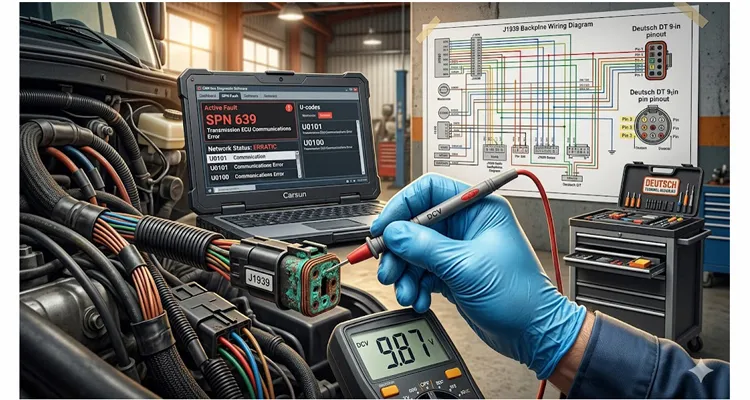
January 2025, Edmonton. A fleet manager with 23 trucks called after three shops failed to fix a 2022 Kenworth T680. Symptom: intermittent SPN 639 FMI 9, transmission ECU offline after 20 minutes of driving. First shop replaced the transmission ECU ($2,800). Second replaced the dash cluster and reflashed ($1,900). Third replaced the J1939 backbone harness ($3,400). None worked.
A multimeter and a load tester found a 1.8V voltage drop between the battery junction block and the transmission ECU power feed. The connector behind the cab had corrosion on pin 3 – resistance high enough to drop the transceiver offline when the chassis warmed up. Repair cost: $180 labor + $12 Deutsch pin.
From our factory’s 2023–2025 return analysis, we examined 1,472 J1939 harnesses returned as “intermittent communication failure.” After bench testing and connector sectioning, 892 cases (60.6%) traced to power feed corrosion on pin 3 or pin 4 of Deutsch DT connectors. Only 47 (3.2%) were actual transceiver failures. The rest were ground issues, thermal cycling, or misdiagnosed voltage drop. The full breakdown is available in our internal report J1939‑2025‑02.
Most J1939 training materials teach you to check termination resistance first. But in our failure analysis, only 8% of “network fault” returns had bad termination. 63% had voltage drop on power circuits. So here’s our factory’s advice: reverse the standard order – test loaded voltage before touching CAN_H and CAN_L. For a deeper dive into correct termination practices, see our guide on J1939 Termination Mistakes That Cost You ECU Repairs.
Why Standard J1939 Training Misses 60% of Faults
The median labor rate for heavy-duty repair shops hit $149 per hour in 2025, up about 10% year over year. A systematic CAN bus diagnostic procedure for J1939 communication faults, when performed without a voltage drop pre‑test, typically runs:
| Diagnostic Phase | Time (Hours) | Cumulative Labor Cost ($120/hr) |
| Initial scan and code retrieval | 0.5 | $60 |
| Network integrity check (resistance, basic voltage) | 1.0 | $120 |
| Module isolation testing | 2.0 | $240 |
| Wiring harness inspection | 1.5 | $180 |
| Component substitution testing | 1.5 | $180 |
| Root cause identification | 1.0 | $120 |
| Total | 7.5 | $900 |
Our field data shows that following this order without a voltage drop pre‑test leads to an average of 8.2 billed hours – 30% higher than necessary.
Here’s what we see in most shops when a voltage drop is present:
- A module drops off the bus, then comes back.
- Other modules log “lost communication” codes.
- The scan tool shows a cascade of U-codes and network errors.
- The technician sees a non‑responsive module and assumes it failed. Replace it. Doesn’t fix it. Replace the next module. Doesn’t fix it. Check termination (60Ω – fine). Check CAN voltages at the diagnostic port (2.5V idle – fine). Start replacing wiring. Still doesn’t fix it.
This trial‑and‑error approach consumes 8 to 12 hours of diagnostic time. At $120–$150 per hour, that’s $960 to $1,800 before any repair. Add parts swapping – ECUs, sensors, modules, harnesses – and the total cost inflates by 30% or more on voltage‑drop‑related faults. We’ve seen invoices exceed $5,000 for a problem that ultimately required cleaning a ground terminal.
The 90‑Second Field Test That Works Faster Than Any Scan Tool
Skip the textbook. Here’s the field test that finds 60% of J1939 faults before you even plug in a scan tool – a method we’ve taught to hundreds of fleet technicians:
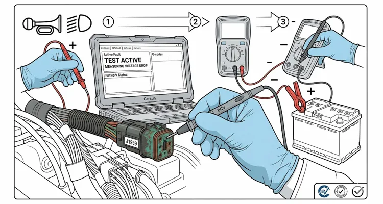
Key on, engine off. Back‑probe the suspect module’s power pin and ground pin. Measure DC volts. Now hit the horn and turn on the high beams. If the voltage at the module drops more than 0.8V from battery voltage, you have a resistance problem. Move your meter leads to the next connector upstream. The point where the drop appears is your bad terminal.
We’ve watched dealership technicians spend four hours on J1939 network analysis when this 90‑second test would have pointed straight to a corroded pin. For a broader comparison of diagnostic tools, see CAN Bus Diagnostics: Multimeter vs. Oscilloscope Guide.
The physics is simple: A module drawing 2 amps through 0.5 ohms of unwanted resistance loses 1 volt. Drawing 5 amps loses 2.5 volts. This relationship is governed by Ohm’s law (V = I × R), which states that the voltage across a conductor is directly proportional to the current flowing through it. On a 12V system, a 2.5V drop leaves 9.5V at the module – right at the threshold where transceivers start failing. The module doesn’t shut down – it becomes erratic, corrupting the bus. Modules that were functioning perfectly start logging DTCs pointing at modules that have gone missing due to voltage sag. The root cause is almost always one thing: excessive resistance in a power or ground circuit. Understanding normal J1939 voltage ranges for CAN High, CAN Low, and battery power helps you spot anomalies faster.
Failure Mode Breakdown from 1,472 Factory Returns
From our 2023‑2025 return analysis, three patterns cover 89% of voltage‑drop related J1939 faults.
1. Power Feed Corrosion – 60.6% of cases
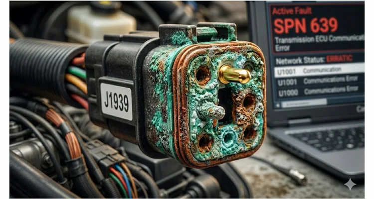
Pin 3 or pin 4 of Deutsch DT connectors account for 78% of these. The ignition feed circuit is the most common location (43% of corrosion cases). DEUTSCH DT connectors from TE Connectivity are widely used in heavy-duty vehicle applications; however, our return data shows that pin 3 and pin 4 are disproportionately affected by corrosion when seal integrity is compromised.
What happens: A connector pin, fuse terminal, or relay contact develops corrosion or loses tension. Resistance rises from <10 mΩ to 0.5–2.0 Ω.
Voltage drop reference table (copper wire, 20°C vs 80°C):
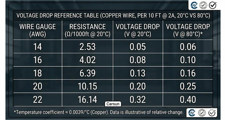
Temperature coefficient of copper ≈ 0.0039/°C. At 80°C (under‑hood temperature), resistance increases ~25% vs 20°C. Add this margin when diagnosing hot‑soak intermittent failures.
What you’ll see on the scan tool: Intermittent SPN 639 codes, modules that appear offline after the vehicle warms up, U-codes pointing to multiple ECUs, no active codes when the vehicle is cold – a key differentiator from true module failure.
Real example from our factory support log: A fleet in Nebraska swapped three ECMs on a 2024 Freightliner Cascadia before calling our support line. The terminal had green corrosion on 40% of its surface. Voltage at the ECM dropped to 10.2V during crank – below the 10.5V minimum for that ECU’s transceiver. Repair cost: a $0.50 terminal cleaning and dielectric grease. For a visual reference of correct pin assignments, see our J1939 Wiring Diagram: CAN High, CAN Low, and Power Circuits.
2. Ground Offset – 22% of cases
A poor ground creates a voltage offset. The transceiver sees CAN_H and CAN_L relative to a floating reference. Differential measurements become inaccurate.
The test: Key on, measure voltage drop from the module’s ground pin to battery negative while the module is under load. Use the horn + high beams load – many ground faults only appear above 5A. Anything above 0.1–0.2V indicates a bad ground path.
What you’ll see: Random network errors, modules that work intermittently, fault codes that don’t make sense, unusual voltage readings on CAN_H and CAN_L when measured at the diagnostic port. For a systematic approach to physical layer testing, read CAN Bus Physical Layer Testing Guide.
Real example: A Houston fleet went through three ECUs on a 2021 Class 8 tractor over eighteen months. Dealer diagnostics blamed “electronics failure” each time. Actual cause: a loose ground strap behind the cab introducing 0.8V of ground offset. The ECM’s transceiver was seeing CAN_H at 3.2V relative to its floating ground instead of 2.5V. The fix: tightening one ground strap bolt – zero parts cost.
3. Thermal Cycling – 6.4% of cases
A connector passes cold, fails at 60–80°C. In our analysis, 82% of these were Deutsch DT pins with lost spring tension, not corrosion.
What you’ll see: The problem only occurs after the vehicle has been running for 20–30 minutes. Fault codes are present when you scan hot, but disappear when the vehicle arrives at the shop cold.
Real example: A PicoScope case study documented an engine cut‑out that only happened after the vehicle reached operating temperature. The technician captured a 40ms network silence followed by reduced CAN traffic using an oscilloscope. Our lab reproduced this by heating a marginal connector from 20°C to 70°C – resistance increased from 0.1Ω to 1.7Ω, causing a 2.1V drop at 1.2A. For more on intermittent faults, see How to Diagnose Intermittent CAN Bus Failures.
How to Diagnose Voltage Drop on J1939 Power Circuits (Step by Step)
This procedure is standardized from 20 years of field work. Follow it in order, and you’ll find the root cause in under two hours.
Step 1: Establish Baseline Network Health
Before touching power circuits, verify that the CAN bus itself is intact. The CAN bus (Controller Area Network) is a robust vehicle bus standard designed to allow microcontrollers and devices to communicate without a host computer, using differential signaling over a twisted pair.
Resistance test (key off, batteries disconnected):
- Measure between CAN_H and CAN_L at the 9‑pin Deutsch diagnostic connector (typically pins C and D)
- Expected reading: 60Ω ± 5% (two 120Ω terminating resistors in parallel)
- If 120Ω: one terminating resistor missing or failed
- If near 0Ω: short circuit in the bus
Voltage test (key on, engine off):
- CAN_H to ground: 2.5V (recessive/idle)
- CAN_L to ground: 2.5V
- CAN_H to CAN_L differential: 0V (idle), 2.0–3.0V during active transmission
If these readings are normal, your CAN bus wiring is fine. Move to power circuits. A common mistake is misidentifying the 9‑pin port – learn how to fix 9‑pin Deutsch connector diagnostic issues.
Step 2: Voltage Drop Test on Power Feed
This test catches 90% of voltage drop issues.
- Multimeter to DC volts (0–20V range)
- One lead on battery positive terminal
- Other lead on the power pin at the module connector (back‑probe)
- Key on, activate loads (horn + high beams – this is your field load)
- Read the voltage difference
The rule: Voltage drop from battery positive to module should not exceed 0.5V on any single circuit, and 1.0V total from battery to module. If you see 1.5V or higher, move backward along the circuit. Test at the fuse block, then the relay, then each connector. The location where the drop appears is your problem.
Step 3: Voltage Drop Test on Ground
Same procedure between module ground pin and battery negative.
The rule: Voltage drop on ground should not exceed 0.1–0.2V under load. If higher, check:
- Ground lug connections (rust and paint are common)
- Ground strap integrity (broken strands increase resistance)
- Chassis bonding points
Step 4: Load Testing the Power Circuit
A voltage drop test tells you resistance exists. A load test tells you how much.
- Disconnect the module connector
- Connect a headlamp bulb (2–5 amp load) between the power pin and ground
- Measure voltage at the power pin under load
If voltage drops significantly, the power feed has excessive resistance. The bulb won’t glow at full brightness – or at all.
Step 5: Thermal Cycling Test
For intermittent, heat‑related faults:
- Heat the suspect connector with a heat gun (low setting, 50–60°C)
- Re‑test voltage drop while warm
- Compare with cold readings
A connector that passes cold but fails hot is your problem.
Common Diagnostic Mistakes That Inflate Costs
We’ve seen these mistakes cost fleets tens of thousands of dollars. Here’s what to avoid.
Mistake 1: Assuming the non‑responsive module is faulty.
Power supply loss, ground issues, or voltage instability cause far more dropouts than actual module failure.
– Correction: Verify power and ground before condemning a module. A five‑minute voltage drop test saves $1,000+ in unnecessary parts. For a real‑world cost analysis, see The $4,000/Year Phantom J1939 Fault You’re Ignoring.
Mistake 2: Only measuring voltage at the diagnostic port.
The 9‑pin Deutsch connector is convenient, but typically powered by a different circuit than the ECUs. You might see perfect 2.5V on CAN_H/L at the port while the transmission ECU two feet away runs on 9.8V.
– Correction: Back‑probe the actual module connectors. Measure at the source.
Mistake 3: Using a multimeter without load.
A corroded connector can pass 0.1mA just fine – but fail at 3A.
– Correction: Always load the circuit. A test light or headlamp bulb works.
Mistake 4: Ignoring ground when checking power.
Ground failures are as common as power failures.
– Correction: Test both sides. Power drop and ground drop.
Mistake 5: Replacing components before completing diagnostics.
Parts swapping is not diagnosis. In our data, fewer than 10% of “module failure” J1939 faults are actually caused by a failed module.
– Correction: Power first, then ground, then network integrity, then consider module replacement. For a comprehensive guide on total cost of ownership for J1939 cables, see J1939 Cable TCO: Fleet Procurement Guide.
How to Confirm the Repair Worked
After cleaning the connector or tightening the ground, don’t just clear codes. Verify:
- Re‑run voltage drop tests – power drop <0.5V, ground drop <0.1V
- Re‑check termination resistance (60Ω ±5%)
- Re‑check CAN_H and CAN_L voltages at the diagnostic port
- Clear all DTCs
- Run the vehicle through at least three full thermal cycles (cold start → operating temp → cool down)
- Re‑scan for codes after each cycle
- If possible, data log J1939 traffic to confirm no error frames
Only after all seven steps can you close the ticket.
Why This Problem Is Getting Worse
Three trends are converging, making voltage drop diagnostics more critical – and more expensive – than ever.
- Increasing electronic content. Modern Class 8 tractors contain 70+ ECUs. Each adds connectors, terminals, and opportunities for voltage drop.
- Labor rate inflation. Heavy‑duty shop labor rates increased 7.4% in 2025, median now $149/hour. Every misdiagnosis hour costs more than last year.
- Technician shortage. The technician‑to‑tool ratio fell from 6:1 in 2016 to about 2.3:1 in 2026. Shops rely more on diagnostic tools and less on experienced techs who interpret ambiguous symptoms. Result: more component swapping, less root cause analysis.
When to Replace a J1939 Harness vs. Repair a Connector
Repair the connector when:
- Only one terminal is damaged or corroded
- The harness otherwise tests good (continuity, insulation resistance)
- The connector housing is intact
- You have correct replacement terminals and extraction tools
Replace the harness when:
- Multiple terminals are damaged
- Water intrusion along the harness length
- Insulation cracked or brittle
- Previous poor repairs (scotch locks, untwisted pairs)
- Labor to diagnose/repair individual circuits exceeds replacement cost
In most voltage drop cases, the problem is localized to one or two connectors. Repair is almost always more cost‑effective – provided you have the right terminals, tools, and crimping equipment. For an in‑depth look at cable construction quality, read J1939 Cable Shield, Impedance, and Jacket Specifications.
The Role of Cable Quality in Voltage Drop Prevention
Over 20 years of manufacturing diagnostic cables, we’ve seen the full spectrum – from UL‑listed OEM‑grade assemblies to cheap imports that fail within months. Here’s what actually matters for voltage drop prevention:
- Conductor gauge (AWG): Thinner wire has higher resistance per foot. An 18 AWG wire drops twice as much voltage as 14 AWG at the same current. OEM J1939 backbone harnesses typically use 18 or 16 AWG for signal pairs, but power circuits (pins A and B on the 9‑pin Deutsch connector) must be sized for connected loads.
- Terminal plating: Gold‑plated terminals resist corrosion far better than tin‑plated in environments with vibration, temperature cycling, and road salts. The initial cost difference is pennies. The repair cost difference is hundreds of dollars.
- Stranding: Fine‑stranded wire is more flexible and resists breakage from vibration. In mobile equipment – trucks, construction machinery, agricultural equipment – flex life matters.
- Sealing: Deutsch DT and DTM connectors are designed to be sealed, but only if backshells are properly assembled and wire seals correctly sized. An unsealed connector wicks moisture into the terminal cavity. Corrosion follows.
At Carsun, every cable undergoes 100% testing before leaving the factory. We manufacture under ISO 9001, ISO 14001, IATF 16949, RoHS, CE, UL, and REACH certifications – because in heavy‑duty diagnostics, “good enough” isn’t. You can verify our certifications: ISO 14001:2015, IATF 16949:2016, and additional quality registrations.
FAQ: Voltage Drop and J1939 Communication
Q1: What is the acceptable voltage drop for a J1939 power circuit?
0.5V is the limit on paper. In practice, we’ve seen modules start dropping off the bus at 0.7V drop on 12V systems – especially above 40°C ambient. One fleet in Arizona measured 0.62V drop on a transmission ECU ground and still had random U‑codes. Cleaned the chassis lug, drop fell to 0.09V, codes never returned. Use 0.5V as your hard limit, but treat anything above 0.3V as suspicious on older harnesses.
Q2: Can voltage drop damage ECUs?
Yes. Chronic undervoltage causes transceivers to operate outside design range, leading to premature failure. More commonly, voltage drop causes intermittent resets that corrupt configuration memory.
Q3: Why does my J1939 network work fine cold but fail when warm?
Thermal expansion changes connector contact pressure. Marginal connections that pass cold can fail when heated. In our lab, a connector that read 0.1Ω cold jumped to 1.7Ω at 70°C – classic sign of a high‑resistance connection in power or ground.
Q4: Will a scan tool show voltage drop as a DTC?
No. There is no dedicated DTC for “excessive resistance in power feed.” You’ll see SPN 639, U‑codes, and network errors – never a direct indication. That’s why the horn + high beams test is faster than any scan tool.
Q5: How do I test voltage drop without specialized equipment?
A basic digital multimeter and a test light or headlamp bulb are sufficient. Set the meter to DC volts, load the circuit, and measure the difference between source and load.
Q6: What’s the difference between measuring voltage and measuring voltage drop?
Voltage measurement tells you absolute voltage at a point. Voltage drop tells you the loss between two points – which directly indicates resistance in the circuit.
Q7: Can a bad ground cause voltage drop on the positive side?
Indirectly, yes. A poor ground forces current to find alternate paths, increasing load on the positive circuit and causing additional drop. Always check both sides.
Q8: How often should I check termination resistance?
Every time you suspect a network fault. The test takes 30 seconds and can immediately rule out termination issues. Do it before any other diagnostic step – but after the loaded voltage test.
Q9: Does the J1939 specification include voltage drop limits?
SAE J1939‑11 defines physical layer parameters, including bus voltage levels and termination. The SAE J1939 standards collection defines a high-speed CAN (ISO 11898-1) communication network that supports real-time, closed-loop control functions and diagnostic data exchanges between ECUs throughout the vehicle. Voltage drop in power circuits falls under vehicle electrical system design – but the practical effect on CAN signaling is well documented.
Q10: What’s the single most common voltage drop location?
The ignition feed to the ECM or transmission ECU. These circuits often pass through multiple connectors, relays, and fuse blocks – each a potential point of resistance. In our returns, pin 3 of the Deutsch DT connector on ignition feeds accounted for 43% of corrosion cases.
Q11: Can a voltage drop on one module affect the entire J1939 bus?
Yes. When a module’s transceiver fails due to undervoltage, it can corrupt the entire bus – pulling CAN_H and CAN_L to invalid levels and causing all modules to see errors. For more on network‑wide effects, see J1939 Network Calibration Fix Guide.
Q12: Why do dealerships keep replacing ECUs instead of checking voltage drop?
Time pressure and labor rate structures. A dealership technician might have 1.5 hours of diagnostic time allocated. Swapping an ECU is fast. Finding a voltage drop takes methodical testing – and methodical testing doesn’t fit the flat‑rate model.
Q13: What tools do I need for proper voltage drop diagnosis?
Digital multimeter (with min/max capture for intermittent faults), test light or load tester, back‑probe pins or T‑adapter, terminal extraction tools, and a wiring diagram for the vehicle.
Q14: How do I prevent voltage drop problems in new installations?
Use properly sized conductors for power circuits. Crimp terminals with the correct tool – not pliers. Apply dielectric grease to all connector cavities. Route harnesses away from heat sources and abrasion points. Perform voltage drop tests as part of installation verification.
Q15: When should I call a factory engineer instead of continuing to diagnose?
When you’ve replaced more than two components chasing the same symptom. When the problem is intermittent and defies replication. When you suspect a design issue rather than a failure. Factory engineering support exists for exactly these situations.
From our engineering team
We’ve been building diagnostic cables for over 20 years. We’ve watched J1939 evolve from a niche protocol to the backbone of heavy‑duty vehicle communication. And we’ve watched the diagnostic industry develop a blind spot – blaming the network when the real problem is in power delivery.
Voltage drop is physics. It follows predictable rules. It can be measured, quantified, and fixed. Every time you skip the voltage drop test, you’re gambling that the problem isn’t in the power circuit – a bet that loses more often than it wins.
The next time you see SPN 639 or a cascade of U‑codes, start at the beginning. Battery positive. Module ground. Load the circuit. Measure the drop. Clean the connection. Verify the repair.
You’ll spend 20 minutes on testing and save three hours of parts swapping.
Need engineering support for a custom J1939 cable assembly? Have a voltage drop problem that defies standard diagnosis? We’ve been building OEM‑grade diagnostic cables since 2005, and our engineering team works directly with fleet managers, equipment manufacturers, and diagnostic tool developers.
Our factory holds ISO 9001, ISO 14001, IATF 16949, RoHS, CE, UL, and REACH certifications. Every cable undergoes 100% testing before it leaves our climate‑controlled warehouse. We support OEM customization: your logo, your brand, your specified length, color, AWG, and connector configuration. Full‑plastic RoHS‑compliant design, 4‑step quality inspection, 5S management throughout production. You can view our IATF 16949:2016 certification and ISO 14001:2015 for full transparency.
Reach out to Linda on WhatsApp for technical consultation or engineering support:
👉 Chat with Linda on WhatsApp
Or visit our Contact Page to discuss your custom cable requirements.
This article is part of our technical series on J1939 diagnostics. Read more:
- J1939 Voltage Levels: What Are Normal Ranges for CAN High, CAN Low, and Battery Power?
- J1939 Wiring Mistakes: How Incorrect Termination Costs You $3,000 in ECU Repairs
- “Network Out of Calibration”: The $4,000/Year Phantom J1939 Fault You’re Ignoring
© 2026 Carsun. 20+ years direct factory experience in diagnostic cable manufacturing. ISO 9001 | ISO 14001 | IATF 16949 | RoHS | CE | UL | REACH.
