

Introduction
The one that sticks with me—Alberta, maybe two years ago. Fleet manager. New Peterbilt, old Volvos. His telematics gateway was showing “no data,” and he was already looking at a $12,000 replacement quote. I asked for photos of his diagnostic ports. One was a 6-pin Deutsch. One was a 9-pin. He thought it was just a shape problem. It wasn’t.
We solved it in 20 minutes. Right J1939 Type 1 to Type 2 adapter, one configuration change. No $12,000 gateway replacement.
Why this J1939 adapter matters, how to pick one that won’t fail, and the J1939 Type 1 to Type 2 adapter installation mistakes I keep seeing on brand-new equipment—that’s what this covers.
The Typical Scenario: A Mismatch in the Machine
You don’t realize you need a J1939 Type 1 to Type 2 adapter until you’re standing in a workshop with a laptop in one hand and a multimeter in the other, staring at two ports that refuse to cooperate.
I’ve seen this three ways.
First: a 2015 Cat loader with a new Cummins engine controller. The controller expects a J1939 Type 2 port (9-pin). The loader has a J1939 Type 1 port (6-pin). No adapter means no communication—and the machine won’t start until the ECU sees the data link.
Second: telematics. A fleet in Texas bought 40 tracking units with Type 2 pigtails. Half their equipment is Type 1. They assumed they could just splice the wires. They didn’t realize the J1939 pinout differences until they lost CAN communication on a 2020 Kenworth.
Third: diagnostic tools. A customer called me because his $8,000 scan tool wouldn’t talk to his 2017 John Deere excavator. The tool came with a J1939 9-pin cable. The excavator has a 6-pin Deutsch connector. He thought the tool was broken. It wasn’t.
This isn’t just about mismatched ports—it’s about the cost of getting it wrong. A fleet in the Midwest once replaced a telematics gateway, two ECUs, and a wiring harness before realizing they were chasing a J1939 Type 1 vs Type 2 mismatch. The full breakdown of that $5,000 mistake walks through exactly how misidentifying the diagnostic port cost them weeks of downtime.
The Technical Roots: Why It’s Not Just a Shape Issue
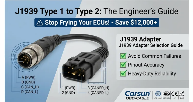
The original 6-pin J1939 Type 1 is brutally simple. Four active pins: power, ground, CAN_H, CAN_L. It was designed for off-highway equipment—dirt, vibration, rain. You could drop it in mud, wipe it off, and it’d still work.
The 9-pin J1939 Type 2 came later, mostly for on-highway trucks. It kept the same CAN lines but added pins for J1708 and a secondary CAN bus. Why? Because truck manufacturers were layering in more systems—ABS, transmissions, body controllers—and not all of them migrated to J1939 protocol at the same time. The SAE J1939 standards collection defines the complete framework, including the physical layer specifications that dictate how these connectors should behave.
Here’s the part that doesn’t make it into the standards documents: I’ve opened up cheap passive J1939 adapters where the manufacturer just wired pin-for-pin without thinking about what those extra pins do. They’ll connect a Type 2 device’s J1708 line to a Type 1 port’s power pin. That’s how you fry an ECU.
The result? Network goes silent. Your diagnostic tool reads “No Communication,” and you start replacing parts you don’t need.
We don’t build passive J1939 adapters for this reason. Every J1939 Type 1 to Type 2 adapter that leaves our ISO 9001-certified floor is 100% tested for continuity and isolation to prevent this exact failure mode.
Building a Reliable J1939 Type 1 to Type 2 Link
Start With the “Brain”
When I sit down with an engineer to spec out a solution for a mixed-fleet environment, I start with one question: what’s the brain?
If it’s a diagnostic scan tool, it expects certain pins to carry certain protocols. If it’s a telematics device, it might be drawing power from the port. That changes everything. I had a case where a customer’s tool was looking for J1708 on pins A and B, but the vehicle only had CAN on pins C and D. A standard J1939 passive adapter wouldn’t fix that. We had to build one that terminated the J1708 lines so the tool wouldn’t hang waiting for a signal that was never coming.
Map the Power Requirements
Power is where people get tripped up. J1939 Type 1 ports usually provide 12V or 24V on pin A. J1939 Type 2 ports often expect power on pin 1. If your device draws power from the port, verify voltage compatibility. A 24V device plugged into a 12V port won’t power on. A 12V device plugged into a 24V port will fry. If your device is externally powered, I always recommend a J1939 adapter with isolated power pins—especially for aftermarket telematics units.
Verify CAN Bus Termination
Termination matters more than most people think. J1939 protocol requires a 120-ohm resistor at each end of the bus. If you’re inserting a J1939 Type 1 to Type 2 adapter in the middle, you might be altering the network topology. A good adapter doesn’t add termination. It just bridges CAN_H and CAN_L from Type 1 pins (typically C and D) to Type 2 pins (typically C and D on the 9-pin). For a deeper dive, see our guide on CAN bus physical layer testing.
Select the Correct Cable Construction
Cable construction depends on where it’s going. Workshop? Short 0.5m to 1m coiled cable is fine. Permanent install in a vehicle cab? You need a rugged, straight J1939 adapter cable with strain relief. In high-EMI environments—near alternators or ignition systems—double-shielded cable (foil plus braid) with a properly connected drain wire. We use 22 AWG for signal lines, 18 AWG for power lines to handle current draw without voltage drop. For more on J1939 cable shielding and impedance, we’ve covered that separately. The physical robustness of these connectors is no accident—TE Connectivity’s Deutsch DT series specifications show they’re designed to handle 20G vibration and temperatures from -55°C to +125°C, which is exactly why they’re the industry standard for heavy-duty applications.
Mount It Properly
Physical mounting: if it’s permanent, secure it away from moving pedals, HVAC vents, and water intrusion zones. I’ve seen too many “temporary” J1939 adapters taped to a wiring harness, only to have the connector pins corrode within six months. We use IP67-rated overmolding on our permanent install J1939 Type 1 to Type 2 adapter for this reason. For extreme environments, our J1939 ArmorLink vibration-validated assemblies are built to survive mining and agricultural conditions.
Common Mistakes I Keep Seeing
I’ve been in this industry for 20 years, managing our factory floor in Shenzhen where we build these cables. I see the same J1939 adapter installation mistakes over and over.
1. Assuming All 9-Pin Ports Are J1939 Type 2
Some 9-pin ports use the same physical connector but follow the older J1708 standard only. Plug a J1939 Type 2 adapter into a J1708-only port and you get a “Bus Off” error immediately. I’ve had customers swear their J1939 adapter was defective until we walked through that one. If you’re working with older equipment, our J1708 diagnostics guide covers the differences.
2. Forgetting the 120-Ohm Terminating Resistor
We had a customer in Texas who replaced three adapters before we figured out his asphalt paver’s terminating resistor was built into the original connector he removed. He didn’t just need an adapter—he needed a terminated J1939 adapter with a 120-ohm resistor built in. We now mark our terminated J1939 adapters clearly for applications where the end node is removed.
3. Using a Cheap “Molded” Adapter for High-Vibration Applications
A $15 molded J1939 adapter from an online marketplace has no strain relief. In a mining truck, vibration will cause the internal solder joints to crack within 90 days. We use a full-plastic design with overmolded connectors and a 4-step quality inspection process specifically for vibration resistance. Costs more to make. Doesn’t leave a customer stranded. Our crimp vs. solder vibration reliability guide explains why this matters.
4. Ignoring the Drain Wire
If your J1939 shielded cable has a drain wire, it must be properly connected to the connector shell (chassis ground). If it’s left floating, it acts as an antenna, picking up noise. If it’s connected to signal ground (pin A), it creates a ground loop. A properly built J1939 Type 1 to Type 2 adapter connects the shield to the connector shell only at one end—drains noise without creating a loop. For more, see our CAN bus shielding and filtering guide.
5. Mismatching Voltages on Aftermarket Devices
A customer in Europe called me because his telematics device wouldn’t power on. He assumed the J1939 9-pin port provided constant power. On his Scania, that pin is switched off when the ignition is off. The J1939 adapter wasn’t the problem. His power source was. We ended up building him a custom harness that tapped a different circuit.
How to Confirm the Fix Is Solid
You’ve installed the J1939 Type 1 to Type 2 adapter. The tool is connected. Now, how do you know you’ve won?
The Voltage Test
With the ignition on (but engine off), measure between pin C (CAN_H) and pin D (CAN_L) on the adapter’s output. You should see 2.5V to 3.5V on CAN_H, and 1.5V to 2.5V on CAN_L. If you see 0V or 12V, the J1939 adapter is not correctly passing the signal.
Voltage readings tell you what is wrong—a short, an open, or missing termination—but they don’t always tell you why it failed. That’s where a structured diagnostic protocol makes the difference. For a deeper walkthrough on using a multimeter to isolate physical layer faults before touching a scan tool, see our guide on forensic hardware-first diagnostics.
The Continuity Test
If you suspect a wiring issue, perform a continuity test from the Type 2 plug’s pins to the Type 1 plug’s pins. Ensure pin-to-pin mapping matches the J1939 pinout standard (CAN_H to CAN_H, etc.) and that there is no cross-continuity between power and signal lines.
The Live Data Test
Connect your diagnostic tool. If you can see engine RPM, coolant temperature, and fault codes, the J1939 Type 1 to Type 2 adapter is working perfectly. If you see data but it’s garbled or intermittent, the issue is likely termination or shielding. For advanced troubleshooting, our CAN bus diagnostics multimeter vs. scope guide walks through the tools you need.
The Long-Term Test
For permanent installations, I tell clients to check the connection after 100 hours of operation. Look for heat discoloration at the pins, corrosion, or looseness. If it passes that, it will likely pass for years.
Related Products: What I Keep in My Own Kit
While we’re on the subject, here’s what I keep in my own kit:
- J1939 9-Pin to 6-Pin Deutsch Adapter Cable – The core product this article is about. I use the 0.5m shielded version for diagnostics—short enough to not get tangled, long enough to reach a laptop on the passenger seat.
- J1939 9-Pin to OBD-II Adapter – I don’t use this often, but when I need to log heavy-duty data with passenger car software, it’s the only way to make it work.
- Custom Length J1939 Cables – Sometimes 1m is too short, sometimes 5m is too long. We’ve done OEM J1939 cable customization for fleet managers who wanted to standardize cable colors across different equipment types. One customer asked us to mold their logo into the overmold—they said it helped prevent theft in their rental fleet.
- Terminated J1939 9-Pin Diagnostic Adapter – For when the original end-of-line connector is removed and you need to add that 120-ohm resistor back into the bus.
Frequently Asked Questions
1. Can I use a J1939 Type 1 to Type 2 adapter to connect a Cummins Insite tool to a 2010 CAT machine?
Yes, provided the tool is a J1939-compliant device. The J1939 adapter only bridges the physical layer. The tool still needs to support the diagnostic protocols (like RP1210) used by the CAT ECU. The adapter doesn’t translate protocols—it just connects them.
2. My J1939 adapter gets warm. Is this normal?
A little warmth, yes. Hot enough to worry about? No. If it’s hot, you have a short. Unplug it and check for cross-wiring. I’ve seen melted connectors from people using passive J1939 adapters where power and ground were swapped. Ours are UL-certified, but nothing survives a direct short.
3. What’s the difference between a passive and an active J1939 adapter?
Passive J1939 adapter is just wires. Active J1939 adapter contains electronics—signal isolation, voltage translation, or built-in termination. For standard J1939 to J1939 connections, passive is fine. If you’re connecting to a non-J1939 protocol or need galvanic isolation, you need active.
4. Can I extend the J1939 adapter length to 10 meters?
Technically, yes, but J1939 has a maximum bus length for reliable communication at 250kbps. Add a 10m extension and you increase signal reflections and latency. For long runs, use a repeater or an active extension cable. We cap our standard J1939 Type 1 to Type 2 adapters at 3m to maintain signal integrity.
5. How do I know if my vehicle uses J1939 Type 1 or Type 2?
Look at the diagnostic port. J1939 Type 1 is a 6-pin Deutsch—round, metal. J1939 Type 2 is a 9-pin Deutsch—larger, rectangular, often plastic or metal. If you’re unsure, email us a photo of your port. We’ll identify it. For a complete breakdown, see our J1939 Type 1 vs Type 2 guide.
6. I bought a J1939 adapter but my scan tool still says “No Communication.”
Check termination first. Then verify the J1939 adapter pinout matches your tool. Some scan tools use non-standard pin assignments on the 9-pin side. We can build custom J1939 pinout adapters for those specific tools.
7. Do you offer RoHS-compliant and REACH-compliant J1939 adapters?
Yes. All our cables are manufactured under RoHS and REACH standards. Lead-free solder, environmentally safe plastics. For aerospace or medical clients, we also offer full material declaration reports.
8. Can I get this J1939 adapter with my company’s logo on it?
Yes. We do this for equipment rental companies and diagnostic tool manufacturers. They mold their logo or part number into the overmold. It helps with inventory control and prevents people from walking off with cables on job sites.
9. What is the typical lead time for a custom J1939 adapter?
For a non-custom standard J1939 Type 1 to Type 2 adapter, we keep stock in our US and EU warehouses for 2-3 day shipping. For custom lengths, colors, or logos, lead time is typically 15-20 working days—design, tooling, and first article inspection included.
10. Is it safe to leave the J1939 adapter plugged in all the time?
Yes, if it’s a high-quality, weather-sealed J1939 adapter. But consider battery drain. Some diagnostic ports are always live. If your adapter is connected to a device that draws power—like a telematics unit—it will drain the battery over time. Use a switched power source or a device with a sleep mode.
Need a Hand With Your Specific Setup?
We’ve been manufacturing diagnostic cables and J1939 adapters for over 20 years. We’re not just a warehouse—we’re a team of engineers who understand the frustration of a silent CAN bus or a melted connector. Our IATF 16949 certification reflects our commitment to automotive-grade quality.
If you’re retrofitting a fleet, developing a new telematics device, or just need a reliable J1939 Type 1 to Type 2 adapter that won’t let you down at the job site, let’s talk. We can review your vehicle schematics, your tool pinouts, and your operating environment to build the exact solution you need.
👉 Get Engineering Support or Request a Custom Quote
- WhatsApp: Chat directly with Linda – I’m on the ground in our factory, and I can get you answers on custom lengths, connector types, and lead times quickly.
- Contact Form: Visit our Contact Page to send us your detailed requirements. Whether you need a simple J1939 adapter or a full harness assembly with ISO 9001 traceability, we’re ready to support your project.
We are ISO 9001, ISO 14001, and IATF16949 certified. All products are RoHS, CE, and REACH compliant. 100% tested before shipment.
