

Over the past decade, the architecture of J1939 has remained consistent across Class 8 platforms—whether you’re dealing with Paccar’s proprietary VECU-2 on a 2023 Kenworth T680, the Detroit DDEC system in a Freightliner Cascadia, or a Volvo VNL with a Cummins X15. The symptom is always the same: intermittent “Out of Calibration” codes that don’t correlate to a specific OEM brand, but rather to a flaw in the physical layer of the network itself.
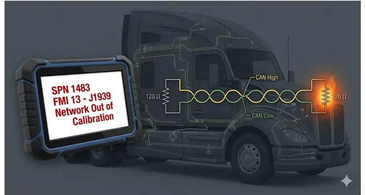
A truck rolls in. The complaint? “Intermittent no-start.” Or maybe “Dash acting weird.” Sometimes it’s “Derate on the highway.” You plug in the diagnostic tool (ServiceRanger, Davie4, or similar). You pull the active codes. There it is. SPN 1483 FMI 13 or SPN 639 FMI 13. The description reads: “Source Address of Controlling Device – Out of Calibration” or simply “J1939 Network – Out of Calibration.”
You clear the code. The truck starts. You hand the keys back. The driver leaves.
Three weeks later, the truck is back on the hook. Towed in. Now it’s a “no-crank, no-communication” situation. You spend two hours chasing wiring diagrams, pulling apart the dash, and testing continuity. Eventually, you replace the Transmission ECU (TCM) or the Vehicle ECU (VECU). The bill hits $4,000 in parts and labor—but mostly labor.
I’m here to tell you: You didn’t fix the root cause. You treated a symptom. And that $4,000 tow-and-repair cycle is happening across your fleet, silently driving up your operating costs. Let’s talk about what “Out of Calibration” actually means, why your technicians might be missing it, and how to kill it for good.
The Problem: A Network That Isn’t “Broken,” Just Misconfigured
Most technicians are wired to look for hardware failures. When we see a J1939 code, our first instinct is to check the wiring harness for chafing, test the terminating resistors, and check for voltage on the CAN lines. If the physical layer checks out, we often throw a module at it.
But FMI 13 is different. It isn’t a short circuit. It isn’t an open circuit. It’s a logic failure.
I’ve dug through the Eaton Cummins documentation enough times to know this: FMI 13 (Out of Calibration) triggers when a specific message—such as the “Source Address of Controlling Device for Engine Control” (SPN 1483)—drops off the bus for as little as 5 seconds. The TCM (Transmission Control Module) is waiting for that message to tell it who’s in charge. When the message goes missing, even briefly, the TCM defaults to a fault state.
This isn’t a hardware fault in the traditional sense. It’s a configuration mismatch or a gateway failure hiding behind a misleading code. In our 20 years of manufacturing J1939 harnesses, we’ve learned that what looks like a software glitch is almost always a physical layer issue that standard diagnostic tools miss.
Why the $4,000 Phantom Cost Accumulates
Let’s break down the financial math that OEMs and large fleets don’t talk about enough. This isn’t just the cost of a tow.
The Intermittent Diagnostic Cycle: Because the fault is intermittent (the message drops for 5 seconds, then comes back), it clears itself after a key cycle. The driver doesn’t report it until it happens three times in a week. Your tech spends 2 hours chasing ghosts.
The Parts Cannon: When you can’t find a wiring break, you replace the component that isn’t “talking.” If it’s a VECU-2 failure causing the C-CAN (Cab CAN) to drag down the voltage—a known issue on 2023 Peterbilt and Kenworth models—you’re swapping modules. A new VECU is $1,200 to $1,800. Programming adds another $300–$500.
Downtime: A truck down for electrical diag costs a fleet roughly $500–$1,000 a day in lost revenue, plus the towing fee.
If you have a fleet of 50 trucks, and 10% of them cycle through this once a year, you’re hemorrhaging capital on a problem that is entirely preventable with correct configuration.
The Deep Dive: Why FMI 13 Happens (The Technical Breakdown)
In a properly functioning J1939 network, every ECU has a unique Source Address (SA) . For transmissions, the standard SA is 3. The TCM listens for the Engine ECU’s message (SPN 1483) to coordinate torque requests, gear shifting, and engine braking. The overall framework for these parameters is defined by the SAE J1939 standard, which specifies how SPNs and PGNs are structured across the network.
FMI 13 triggers when the TCM expects that Engine message, but it isn’t there.
Based on field data and diagnostic guides, here are the three root causes I see most often in heavy-duty applications:
1. The “Ghost” Gateway Failure (VECU / CECU)
This is the most expensive and hardest to catch. The VECU (Vehicle ECU) acts as the gateway for the entire network. If the VECU starts failing internally—as noted by Kenworth Master Technician Gage Bennett—it doesn’t just stop working; it starts pulling the CAN bus voltage down. You’ll measure the bus and see CAN_H at 1.8V and CAN_L at 1.9V instead of the required differential.
The result? All modules on that bus (C-CAN) lose the ability to send or receive messages. The TCM goes into “Out of Calibration” because it literally cannot see the engine. You’ll see a laundry list of codes, but the root cause is the gateway module corrupting the voltage.
2. Termination Corruption
J1939 requires two 120-ohm terminating resistors at each end of the backbone. Most technicians know to look for 60 ohms across the bus. But in a healthy, low-hour vehicle, you’ll see 59.8 to 60.2 ohms.
What matters isn’t the number—it’s the drift.
If you’re reading 67 ohms on a 2022 Peterbilt, that 7-ohm drift isn’t just a “passable” reading. It indicates that either the internal termination resistance inside the VECU or a molded Y-cable has thermally degraded. That drift eats into the noise margin of the differential signal. The ECU isn’t confused because the voltage is “wrong”; it’s confused because the voltage is drifting during the message frame. The physical layer requirements—including termination and shielding specifications—are formally defined in the SAE J1939 physical layer standard, which sets the 120Ω termination and 60Ω total bus resistance requirements. For a deeper dive into J1939 cable specifications—including how shield integrity and impedance control directly impact termination stability—see our guide on J1939 Cable Shield, Impedance, and Jacket Specification.
| Physical Layer Parameter | OEM Specification | Real-World Degradation (Fault Condition) |
| Termination Resistance | 60 Ω (±2 Ω) | >68 Ω (thermal drift in molded cables or ECU internal termination) |
| CAN_H Voltage (to ground) | 2.5V – 3.0V | <2.2V (gateway module sinking current) |
| Shielding Effectiveness | 100% coverage, continuous | PVC jacket breakdown after 3–5 years; dielectric absorption introduces signal skew |
3. Aftermarket Integration Conflicts
This is where I see fleets accidentally creating their own $4,000 problem. You install a telematics gateway, a collision avoidance system (like Bendix), or a power take-off (PTO) controller.
If the aftermarket device is configured to broadcast with a Source Address that conflicts with the TCM (SA 3) or Engine ECU, it creates a “network storm.” The TCM receives the correct message and the conflicting message, calculates a checksum error, and throws FMI 13 because it can no longer trust the data.
Step-by-Step: How to Fix It (And Not Just Clear It)
If you are an engineering manager or a senior fleet maintenance director, you need to standardize this diagnostic flow. Hand this to your lead techs.
Step 1: Establishing the Noise Margin Floor (The 60-Ohm Drift Test)
- Ignition off. Batteries disconnected (or wait 10 minutes for modules to sleep).
- Locate the diagnostic port (9-pin Deutsch or OBD).
- Measure resistance between CAN_H (Pin C) and CAN_L (Pin D) .
Expected: 59.8 – 60.2 Ω in a new, healthy system. Acceptable operational range is 58–62 Ω.
Action:
- If you see 70 Ω or higher: You’re missing a terminator or one has drifted thermally. Track down the backbone ends.
- If you see 50–57 Ω: Possible short or a failing module loading the bus.
- If you see 60 Ω but the fault persists: The termination is intact, but you likely have a “noisy” node or stub reflection. For a detailed walkthrough of CAN bus physical layer testing beyond the multimeter, refer to our CAN Bus Physical Layer Testing Guide.
Step 2: Voltage Validation (The Bias Check)
- Ignition on. Engine off.
- Measure voltage from CAN_H to ground.
- Measure voltage from CAN_L to ground.
Expected: CAN_H 2.5V – 3.0V. CAN_L 2.0V – 2.5V. The sum should be approximately 5.0V.
Red Flag: If the sum is 3.5V or less, you have a short to ground or a failed module (likely the VECU) sinking voltage.
Step 3: The “Divide and Conquer” Node Sweep (Finding the Noisy Actor)
If the physical layer passes but the code returns:
- Disconnect aftermarket devices (telematics, GPS, liftgate controllers) one by one.
- If the code clears, the aftermarket device is either faulty or has a conflicting Source Address. Contact the supplier for a firmware update or configuration change.
- If the code persists, you must isolate the OEM modules. Start unplugging modules from the CAN bus (ABS, TCM, ECM, VECU) until the voltage returns to normal. The last module unplugged is the culprit.
When you need to tap into the network without disturbing existing terminations—especially during the isolation phase—a purpose-built J1939 9-Pin Pigtail Breakout Cable gives you clean access to CAN_H, CAN_L, and ground without introducing stray capacitance or accidental termination shifts.
Step 4: Configuration (The Software Layer)
If the code is active but all hardware checks out, the TCM or ECM is likely configured for a feature that doesn’t exist (e.g., it’s looking for a secondary shift device that isn’t installed). Using ServiceRanger or OEM software, check the configuration:
- FMI 13: Often requires enabling the “Source Address of Engine Controlling Device” message.
- FMI 11 (Mismatch): If the TCM sees a Primary Shift Device message conflicting with a Secondary hardwire signal, you have a configuration mismatch in the driver interface.
For a complete reference that combines these diagnostic steps with cable-level root cause analysis, refer to our structured guide: J1939 Network Calibration Fix Guide.
The Hardware Variable: Why Cable Integrity Matters in J1939
In my 20+ years of experience in the wiring harness industry, I have seen fleets chase “network faults” only to discover that the diagnostic port adapter they were using, or the extension cable, had corroded terminals. We’ve documented similar scenarios where a seemingly minor hardware issue—like a failing 9-pin Deutsch connector—caused weeks of intermittent diagnostic headaches.
J1939 is a high-speed network (250kbps). It is sensitive to impedance changes.
If you are using a generic, non-shielded OBD cable to run extended diagnostics or to permanently mount a telematics unit, you are introducing a variable. A cable that isn’t constructed with proper twisted-pair geometry and 100% shielding can act as an antenna, introducing RF noise into the network. This noise can corrupt the data packet, triggering SPN 639 or 1483 FMI 13.
Engineering Note: Many aftermarket “J1939 Y-cables” on the market use PVC insulation. While cheaper, PVC has a higher dielectric absorption than polyethylene. Over time, this “memory effect” distorts the rise time of the CAN waveform. If you are diagnosing intermittent FMI 13 faults, verify your breakout cable uses cross-linked polyethylene (XLPE) insulation or automotive-grade TPU.
When we design J1939 breakout cables or custom adapters for our clients—who range from mining operations to OEM integrators—we adhere to strict protocols:
- Twisted Pair: We maintain the exact twists per inch to preserve the differential signal.
- Shielding: Full plastic design with a grounded shield to reject EMI.
- Termination: We ensure that our cables do not introduce an extra 120-ohm resistor unless specifically requested for end-of-line testing.
For fleets dealing with persistent J1939 network out of calibration issues, we’ve developed a structured approach that combines these hardware disciplines with systematic diagnostics. You can find the complete workflow in our J1939 Network Calibration Fix Guide.
FAQ: The “Out of Calibration” Questions We Get Asked
Q1: I cleared the code and it went away. Is the truck fixed?
No. FMI 13 requires the fault condition to be absent for 10 seconds to clear the code. If it cleared, the network was stable for 10 seconds. That 10-second window is the key: the fault isn’t gone—it’s just waiting for the next voltage dip, vibration, or thermal cycle to reappear.
Q2: Why do I get this code after installing a 3rd party telematics device?
The device is likely using a J1939 Source Address that is already reserved for a core powertrain component (usually Address 0 for Engine, 3 for Transmission). You must either configure the device to use an “unused” address or ensure the device is “listen-only” (no transmissions).
Q3: I measured 60 ohms, but I still have the code. Now what?
60 ohms confirms the backbone is terminated. You now have a “stuck” or “noisy” node. Use the isolation technique (Step 3 above). Unplug modules until the bus voltage stabilizes at 2.5V/2.5V. The last module unplugged is the culprit.
Q4: Can a damaged 9-pin diagnostic connector cause this?
Absolutely. If the pins are spread or corroded, the TCM loses intermittent contact with the J1939 backbone. If you are using a permanently installed cable for telematics, ensure the pins are gold-plated and weather-sealed to prevent fretting corrosion.
Q5: Is there a difference between FMI 13 and FMI 14 for these codes?
Yes. FMI 13 (“Out of Calibration”) usually means the message isn’t available. FMI 14 (“Special Instructions”) usually means the message is received, but the data is out of range or the actuator is delayed. FMI 14 often points to a software timing issue or a failing actuator driver.
Q6: Does this happen more on newer trucks (2020+)?
Yes. Master technicians report increasing occurrences on 2023 model year Paccar vehicles (Kenworth/Peterbilt) due to VECU-2 sensitivity. The newer ECUs have faster processors but are more sensitive to voltage drops and signal noise.
Q7: Why does the truck not crank when this fault is active?
Safety logic. If the TCM (Transmission) cannot verify communication with the Engine ECU, it assumes it cannot safely control the neutral start switch. It inhibits the starter to prevent the vehicle from lurching.
Q8: How do I prevent this from happening again after repair?
Beyond replacing the faulty module, review the vehicle’s wiring for “stubs” (unused taps) . In theory, J1939-11 allows stubs up to 3 meters. In practice, on a fleet vehicle with 5 years of vibration, a 1.5-meter stub to an unused telematics port becomes a parasitic reflector.
Here’s how you spot it without a scope:
Measure termination resistance. If it’s 60 ohms but the “Out of Calibration” code returns under heavy engine braking (high EMI), the stub is acting as an antenna. The fix isn’t a new ECU—it’s removing the stub from the backbone and placing it behind a gateway, or installing a dedicated in-line terminator at the stub’s end.
Engineering Support and OEM Customization
For fleet managers and engineers who have moved beyond the “swap parts and pray” phase, the solution lies in understanding the hardware interface as well as the software.
We’ve been manufacturing J1939 harnesses for 20 years—long enough to know that FMI 13 is rarely a software problem.
When a large mining fleet came to us with persistent “Out of Calibration” codes on their Cat 793 haul trucks, the issue wasn’t the ECU. It was the 3-meter non-twisted extension cable they were using to mount the telematics device in the cab. We replaced it with a shielded, twisted-pair harness built to SAE J1939-11 impedance specs (not just RoHS compliance). The fault cleared. That’s the difference between a factory that “makes cables” and a factory that understands signal integrity.
Our facility operates under IATF16949 (automotive quality management), ISO 9001, and ISO 14001 standards, ensuring that every harness—whether it’s a simple 9-pin to OBD adapter or a complex multi-branch J1939 backbone—meets the strict impedance and shielding requirements of the SAE J1939 specification. For details on our quality management systems, see our IATF 16949:2016 Certification Announcement.
If you are dealing with persistent network faults, intermittent “Out of Calibration” codes, or are integrating custom equipment (PTO controllers, telematics, hybrid systems) onto your J1939 network, the physical layer matters.
We offer OEM customization for your fleet or manufacturing line:
- Logo and Branding: Custom labels and wire colors to match your fleet standards.
- Length and AWG: Exact wire gauges and lengths to eliminate coiled service loops that act as antennas.
- Pinout: Specific wiring configurations for non-standard OEM diagnostic ports.
- Materials: RoHS and REACH compliant materials, 100% tested under load.
We also offer dedicated engineering support to help you audit your J1939 network architecture. We can help you identify if the telematics device you are installing is causing a voltage drop, or if your in-cab wiring harness is missing the required termination.
Stop clearing codes and start solving the root cause.
Need help with a persistent J1939 network issue?
Contact our engineering team directly to discuss your fleet’s specific configuration or to request custom hardware solutions.
- WhatsApp Support: Chat with Linda for Engineering Support
- Contact Page: Submit a Custom Cable RFQ or Technical Question
Post-Script for the Engineers
If you are reading this and you are currently fighting a VECU-2 failure on a 2023 Paccar, check your C-CAN terminating resistance with the VECU connected and disconnected. If the resistance jumps drastically, you’ve found your noise source. We have pre-configured breakout harnesses available that allow you to isolate the C-CAN bus without cutting OEM wires.
