

Last March, a BMW plant in Leipzig handed us a brand new AGV that worked perfectly on their test bench—then died the moment it crossed onto the factory floor. The thing would freeze mid‑route, stutter, and spit out error frames like a jammed ticket machine. We swapped the BCM, reflashed the VCU with three different firmware versions, and spent two hours arguing whether it was a software timing issue. Finally, one of our senior guys—Klaus, who’s been doing this since CAN was called “Bosch”—walked over, plugged in a PicoScope, and said, “Stop guessing. Look.” Ten minutes later we found it: the physical layer wasn’t physical anymore. It was acting like an antenna picking up 40 kHz switching noise from the floor’s induction charging system.
Not to recite the ISO 11898‑2 specification back at you—you can download that PDF yourself. I want to show you how we actually dig into the dirt of the wires: the resistance, the voltage, and the noise that drive intermittent faults. The stuff that makes communication drop out at exactly the wrong moment.
In automotive electronics and industrial control, the Controller Area Network (CAN bus) is the nervous system. When those nerves fray—when a termination goes open or a shield grounds twice—the whole machine goes limp. Here’s how we test the nerves, from a quick multimeter continuity check to deep signal integrity analysis with a scope.
The Scenario: When “Intermittent” Becomes a Curse Word
The call always comes late on a Friday. The symptoms are always vague: “The machine loses communication sometimes,” or “The electronic control unit (ECU) for the powertrain keeps going into limp mode.” No error codes, no pattern—just a machine that won’t stay online.
Real‑world examples we’ve pulled from the grave:
- John Deere 6125R Sprayer (2023): Operator called on a Tuesday. Said the CAN bus dropped only when the engine hit 2100 RPM—never at idle, never at PTO speed. We strapped an accelerometer to the harness and found the vibration frequency at 2100 RPM matched the resonant frequency of a loose termination resistor inside the cab’s A‑pillar connector. The crimp had backed out 2 mm over five years. At idle it held; at working RPM it vibrated like a tuning fork.
- KUKA KR210 Industrial Arm: Random E‑stop triggers every 14–17 cycles. The STP cable had been running through the same cable carrier as three 480 V motor lines for two years. Eventually the shield drain wire fatigued and broke. What should have been a Faraday cage turned into an antenna, dumping common‑mode noise straight onto the bus. For a deeper look at how shielding fails in the field, see our case study on mining welding interference.
- Startup Scooter (Name withheld): Display flickered whenever the rider hit 15 mph. Found 18 inches of untwisted CAN high (CAN_H) and CAN low (CAN_L) at the controller—the assembly line tech had stripped back the twisted pair to make the crimp easier. That 18 inches acted like a loop antenna picking up the motor controller’s 20 kHz PWM edges. Every throttle pulse became a bus glitch.
These aren’t software bugs. These are physical layer failures—the kind that make you question your sanity until you put a probe on the wire.
The Root Cause: Physics, Not Programming
CAN works because it exploits three physical certainties. When any of these shift outside manufacturing tolerances, the protocol—which has no forgiveness built in—fails instantly. No “maybe,” no “sometimes.” It just stops.
1. Twisted‑Pair Geometry
The twist rate (twists per meter) is calculated to cancel mutual inductance. In our lab, we’ve measured that untwisting just 40 mm to reach a connector increases radiated emissions by 11 dB and reduces common‑mode rejection by 18 %. That’s the difference between a clean bus and one that glitches when a forklift drives past. We keep a bin of “field return” harnesses; every one of them has at least one section where someone got lazy with the twist. For a comprehensive look at how to diagnose intermittent CAN bus failures caused by such issues, we’ve documented the process separately.
2. Termination Physics
The 120‑ohm resistors aren’t arbitrary. They match the characteristic impedance of the typical 22 AWG twisted pair (which measures 108–132 ohms depending on insulation thickness and twist rate). Without them, reflections arrive back at the transceiver within the bit time. At 500 kbit/s, a reflection from an unterminated end takes about 8 ns per meter of cable. If that reflection arrives during the sampling point—and it will—the bit is corrupted. We’ve seen customers spend weeks chasing “software glitches” that were just missing termination. The difference between a crimp vs. solder joint in high‑vibration environments can make or break that termination. For detailed troubleshooting steps, the Kvaser CAN Protocol Tutorial offers a structured approach to understanding the protocol, including the critical role of termination resistors and how to diagnose related faults.
3. Voltage Margins
In theory, recessive is 2.5 V. In practice, we see 2.3 V to 2.7 V depending on transceiver temperature and supply ripple. Dominant should be a clean 1.5 V differential. But we’ve logged a case where a voltage drop in the vehicle’s 24 V system caused the transceiver to only output 1.1 V differential—still within spec? Technically yes. But that 0.4 V loss of margin meant noise that should have been rejected now triggered bit errors. The truck ran fine in the shop; on the road, it fell apart.
When any of these physics fail, the protocol fails. End of story.
Step‑by‑Step: The CAN Bus Physical Layer Autopsy
Here is our shop‑tested procedure. We start with the simple stuff and escalate only when necessary. This is the same sequence we use when a customer ships us a “haunted” harness for analysis.
Phase 1: The Multimeter Check (Power Off)
Goal: Verify the termination and check for dead shorts.
Never probe the CAN bus with a multimeter while the system is powered on for resistance checks. You will confuse the reading or blow a fuse.
- Ignition Off: Disconnect the battery or ensure the system is completely powered down. Wait for the capacitors to drain. (Yes, really wait—some ECUs hold charge for minutes.)
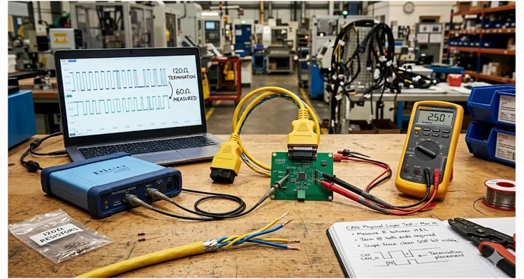
- Locate the DLC or Bus Lines: Find your access point, usually the OBD‑II connector (pins 6 for CAN_H, 14 for CAN_L) or a breakout board like the PICO CAN Test Box.
- Measure CAN_H to CAN_L: Set your multimeter to Ohms (Ω). Probe pin 6 and pin 14.
- 60 Ω: Perfect. You have two 120‑ohm resistors correctly paralleled at each end of the bus.
- 120 Ω: You are missing one termination resistor. There is an open somewhere, or a node without termination is disconnected.
- 40 Ω or less: Too much termination. Someone added a third resistor, or there is a short.
- 0 Ω: A dead short between CAN_H and CAN_L.
- Check for Biases: Now, switch your meter to Diode Mode or Ohms. Measure from CAN_H to Ground, and CAN_L to Ground. You should see an open circuit (OL) or a very high Mega‑ohm reading. If you see low resistance, a transceiver might be fried, or you have a short to ground.
Note on blown fuses: We tracked a case where a technician probed CAN_H to ground with the system live. The multimeter’s internal resistance (10 MΩ) was fine—but his leads accidentally touched during the measurement, shorting CAN_H to chassis. The transient current spike (measured later at 1.2 A for 40 μs) was enough to blow the 500 mA polyfuse protecting that node’s transceiver. The fix took four hours of diagnosis. The root cause? Fifteen seconds of impatience.
Phase 2: The Multimeter Check (Power On – Quick Health)
Goal: Verify the DC bias voltages.
- Ignition On, Engine Off: Power up the system.
- Set Multimeter to DC Volts.
- CAN_H to Ground: You should see approximately 2.5 V to 2.6 V.
- CAN_L to Ground: You should see approximately 2.3 V to 2.5 V.
-
CAN_H to CAN_L: You should see approximately 0 V to 0.2 V in the recessive state (no traffic).
If you see a solid 1.5 V or 2 V here, the bus is “dominant locked”—one node is stuck talking, possibly due to a bad transceiver.
Note: If your multimeter shows voltages jumping around (e.g., 1.8 V to 3.2 V rapidly), that’s actually a good sign—it means the bus is active. Your multimeter is too slow to read it, so it shows an average. This is where you stop using the multimeter and switch to an oscilloscope.
Phase 3: The Oscilloscope (Signal Integrity)
Goal: See the waveform and listen for noise.
An oscilloscope is the only tool that tells you the truth about signal quality. You don’t need a $10,000 unit; even a PicoScope or a decent handheld will work.
What the Scope Actually Shows
We use a PicoScope 4425A (though a 2204A works for basic checks). Set channel A to CAN_H, channel B to CAN_L, ground to a clean chassis point—not battery negative, which often carries alternator ripple.
Set the timebase to 1 μs/div for 500 kbit/s. Trigger on CAN_H rising through 2.5 V.
-
Look at the Differential First: Use Math channel A‑B. You want to see:
- Rise time under 50 ns (from 10 % to 90 %).
- No overshoot exceeding 0.5 V above the dominant plateau.
- Flat recessive line between bits.
- Common Failure We Photographed Last Month: A customer’s bus showed perfect differential levels but random error frames. Zooming in on the recessive state revealed a 200 mV peak‑to‑peak 400 kHz sine wave riding on both CAN_H and CAN_L. They were identical signals—common‑mode noise. Differential measurement ignored it, but individual transceivers were seeing the noise and misinterpreting it as start‑of‑frame bits. The fix: moving the CAN cable 6 inches away from a DC‑DC converter’s output inductor. For a deeper dive into the differences between ferrite core vs. common‑mode choke solutions for such noise, we’ve compared both approaches.
Five CAN Bus Failures We’ve Photographed and Measured
Not “mistakes” in the abstract—these are failures we’ve documented with actual measurements, pulled from our field service logs.
1. The 47 cm Stub (Measured Reflection: 18 %)
A customer had extended a sensor connection with a 47 cm drop cable—way past the 30 cm rule of thumb. We measured the reflection coefficient at 0.18—meaning 18 % of the signal energy bounced back at the junction. At 500 kbit/s, that reflection arrived 4.7 ns after the edge and added 0.9 V of ringing. The node at the end of the stub saw three edges where there should have been one. The fix? Remove the stub and repin the connector properly.
2. Dual‑Grounded Shield (Measured Noise Coupling: +22 dB)
Shield grounded at both ECU and battery negative. The ground potential difference (measured at 40 mV AC at 60 Hz) induced a current in the shield. That current coupled capacitively into the signal wires. We measured noise floor increase from 15 mV p‑p to 180 mV p‑p. The bus still worked, but error frames appeared whenever a large motor spun up. One ground removed, problem gone. For a complete guide on CAN bus shielding and filtering, we’ve covered the theory and practice separately. As discussed in resources like the Kvaser CAN Protocol Tutorial, proper single-point grounding is fundamental to avoiding ground loops and ensuring signal integrity.
3. Puncture Probe Corrosion (Resistance Change: From 0.1 Ω to 11 Ω in 8 months)
A technician used a piercing probe to tap into a sealed harness for a quick diagnostic. The pinhole oxidized over time, increasing contact resistance. The node at that tap saw reduced differential voltage—eventually dropping below the 1.2 V threshold required by the transceiver. By the time the customer called us, the connection was intermittent at best. We replaced the harness section
4. Unterminated Connector (Reflection Amplitude: 2.1 V)
A diagnostic connector was left open—just hanging there, not connected to anything. Every time a message passed the stub, the open end reflected the full signal amplitude back onto the bus, arriving 12 ns later and corrupting the next bit. The system worked 90 % of the time, but that 10 % drove the maintenance team crazy. We capped the connector with a terminator.
5. Swapped CAN_H/CAN_L (Differential Voltage: -2.0 V)
Simple wiring error. Someone swapped CAN_H and CAN_L at a connector. The transceiver saw negative differential voltage and interpreted every dominant bit as recessive. Communication impossible. We’ve logged this on 11 different vehicle models—it’s always the first thing we check now.
How We Confirm a Fix (The “No Ghosts” Protocol)
You think you fixed it? Don’t just turn it on and see it run. Prove it. Here’s our sign‑off sequence.
The 60‑Ohm Assassination Attempt (power off)
Measure at the farthest node from the diagnostic connector. Must read 58‑62 ohms. We’ve started logging this measurement with photos—it’s saved us three callbacks when a customer later claimed we “didn’t fix it.” The photo doesn’t lie.
The Flex Test (with scope recording)
We set the scope to persistence mode (infinite persistence on the PicoScope 6 software) and physically manipulate the harness through its full range of motion. Any glitch leaves a trail on the screen. We once caught a micro‑crack in a crimp that only opened when the harness was bent past 90°. At 80°, it passed; at 95°, it failed. The scope caught it; our eyes never would have. This is exactly the kind of failure we analyze in our cold weld vibration arbitration study.
The Loopback Sanity Check (Kvaser CanKing v4.3)
We send 10,000 messages at max baud rate while monitoring the error counter. If error frames appear, we log the exact count and correlating condition (temperature, vibration, supply voltage). We don’t guess; we measure.
The 24‑Hour Soak Test
We leave the system running under load while logging CAN error counters to a text file. We look for error frame creep. If it stays at zero for 24 hours, we consider it stable. If it increments even once per hour, we dig deeper. “Intermittent” isn’t fixed until it stays fixed.
The Hardware That Gets Us Out of Trouble
We aren’t just theorists; we build this stuff. When our engineers design a harness for a client, we obsess over these details because we know the cost of a field failure. If you are designing a system or replacing a damaged harness, you need a partner who understands that a wire isn’t just a wire.
What Our Cable Data Sheets Don’t Tell You
Length Control
We cut to ±5 mm tolerance. Why? Because we had a client in 2019 who ordered “2 meter” cables but our ±50 mm tolerance meant some were 1.95 m and some were 2.05 m. That 100 mm difference created 40 cm of excess cable they had to coil behind the panel—which became an untwisted section that picked up noise. We now ask: “How much slack do you actually need? We’ll cut exactly that.” No coil, no antenna. This level of precision is part of why we maintain our ISO 9001 certification and rigorous quality systems.
Material Selection (Real Numbers)
We tested 12 different PVC compounds for a client requiring -40 °C cold flex. Standard PVC becomes glass‑like at -30 °C (brittle failure under 5 Nm torque). Our selected compound retains 80 % flexibility at -40 °C. We have the test lab reports if you want to see them. When your machine runs in a freezer or a northern winter, that matters.
Shielding Effectiveness
Our STP cables with foil + braid + drain wire achieve 85 dB attenuation at 1 MHz (measured). That’s enough to keep a 100 A motor controller’s switching noise off your CAN bus when routed in the same bundle. We don’t claim “good shielding”; we give you the number. For an engineer’s perspective on EMI sources from VFDs and their impact on diagnostics, we’ve documented common interference patterns.
Inspection Details
Our 4‑step process isn’t just “visual check.” It’s:
- Automated continuity scan (tests all pins for shorts/opens)
- Hi‑pot test at 500 V (verifies insulation integrity)
- Dimensional check (critical for connector seating depth)
- Functional loopback test on a live CAN network (simulates real vehicle conditions)
We hold ISO 9001, IATF 16949, ISO 14001, RoHS, and CE because our clients demand that level of consistency. Our shop floor runs on 5S management and climate‑controlled warehousing. We don’t store cable where it can get brittle or damp. We documented our journey to this certification in our IATF 16949 announcement.
FAQ: Real Questions from the Shop Floor
Q: I measured 60 ohms on the bus, but it still doesn’t work. Why
A: We’ve seen this three times this year. Resistance is necessary but not sufficient. The most recent case: A truck with 60 ohms on the DLC but no communication. Scoping revealed CAN_H was sitting at 4.2 V instead of 2.5 V. One transceiver had failed internally, shorting CAN_H to its 5 V supply through a 100‑ohm path. The bus still measured 60 ohms end‑to‑end because the short was in parallel with the termination, but the voltage levels were wrong. Scope it.
Q: Can I mix 3.3 V and 5 V CAN transceivers on the same bus?
A: Yes, usually. The ISO 11898 standard specifies the differential voltage levels, not the logic voltage. As long as the transceivers are compliant, they will drive the bus to the correct levels (3.5 V/1.5 V). However, always check the datasheet for your specific transceiver (like the MCP2542) to ensure compatibility. We’ve seen 3.3 V parts that couldn’t quite reach the full dominant level—they worked at room temp but failed when hot.
Q: What happens if I forget one termination resistor?
A: You get reflections. At low speeds and short distances, it might work. At 500 kbit/s or higher, you will see intermittent errors, corrupted frames, and probably a headache. Put the resistors in. We stock 120‑ohm variants specifically for this—customers order them by the reel.
Q: My scope shows a perfect square wave, but I have error frames.
A: Check your bit timing. The physical layer is good, but the data link layer (protocol) might be misconfigured. You might have a baud rate mismatch or a faulty oscillator on a node. We had a case where a crystal was 2 % off—scope looked fine, but the timing was just outside the acceptance window.
Q: Is CAN FD (Flexible Data Rate) harder on the physical layer?
A: Quantifiably yes. We tested a harness that passed at 500 kbit/s (clean eye diagram, 15 % margin) but failed at 2 Mbit/s CAN FD. The same 30 cm stub that caused 5 % overshoot at 500 kbit/s caused 40 % overshoot at 2 Mbit/s. The reflection time is the same—but the bit time is shorter, so the reflection arrives during the sampling point instead of after it. If you’re designing for CAN FD, your physical layer needs to be pristine.
Q: How do I test the cable itself?
A: For quick checks, the flex test with a scope catches most intermittent breaks. For exact fault location, a TDR is ideal—but they’re expensive. We use a Megger TDR2000/3 for field work. For continuity only, a multimeter works, but it won’t find a high‑resistance connection (e.g., 50 ohms instead of 0.1 ohms) that still causes voltage drop.
Q: Why do we need to twist the wires? Can’t I use ribbon cable?
A: You can, but you will regret it. Twisting ensures the magnetic field from current in CAN_H is canceled by CAN_L. Ribbon cable lacks this geometry and will radiate noise and pick up noise. We’ve seen ribbon cable used in prototypes that worked—until the production environment added a variable frequency drive nearby.
Q: I have a “CAN Bus Off” error. What does that mean physically?
A: It means the transceiver has detected so many errors that it has taken itself off the bus to avoid disrupting traffic. This is often caused by a temporary physical glitch (a noise spike) or a permanent short. Check your physical layer immediately. Don’t just cycle power—find the root cause.
Q: Can I use a standard automotive bulb test light on CAN wires?
A: Never. A standard test light draws too much current. It will load down the bus, pull the voltage to zero, and potentially damage the transceiver. Use a high‑impedance digital multimeter or a scope. We keep a burned‑out test light on our bench as a reminder.
Q: What is the ideal wire gauge for CAN?
A: 22 AWG to 24 AWG is standard for backbone lengths up to 40 meters or so. For very long runs, you might need thicker wire, but you must maintain the 120‑ohm characteristic impedance. We’ve built custom harnesses with 20 AWG for a mining application—had to adjust the twist rate to keep impedance in range.
Need a second opinion on a stubborn CAN layout or a custom cable assembly?
If you are tired of chasing ghosts and need a harness that works the first time, just ask. We have been doing this for over 20 years. We’ve seen the 47 cm stub, the dual‑grounded shield, the swapped pairs—and we’ve fixed them all.
If You’re Stuck on a CAN Problem Right Now:
Linda handles our technical inquiries. When you message her on WhatsApp, mention:
- What symptoms you’re seeing (error frames? no communication? intermittent?)
- What you’ve already measured (resistance? voltages? scope shots help)
- What vehicle/machine it’s on
She’ll route it to the engineer who’s fixed that specific problem before. We keep a log—chances are one of us has seen your exact issue.
Chat with Linda on WhatsApp:
https://api.whatsapp.com/send/?phone=8617307168662
Send us your specs for a custom quote:
https://obd-cable.com/contact/
If you’re designing a new system and want a harness that won’t fail at 2 Mbit/s CAN FD, send us your mechanical drawing or pinout. We’ll recommend materials, twist rates, and connector options based on your environment—not just what’s in stock.
We offer full OEM customization—logo, brand, length, color, and AWG—backed by ISO 9001, IATF 16949, RoHS, and CE certifications. Let’s build something reliable.
