

Let’s cut to the chase: your diagnostic scanner is a fantastic historian, but a terrible detective. It logs the event—U0100, U0401—but rarely uncovers the motive. The truth behind a silent module lies not in software menus, but in the copper and insulation. This is where your multimeter shifts from a basic tool to your primary investigative instrument. We’re moving past superficial checks. This guide details a methodical, multimeter-based diagnostic protocol for CAN bus networks that diagnoses the cause, not just the symptom, elevating you from a parts replacer to a true electrical system diagnostician.
The Silence on the Bus: When Modules Stop Talking
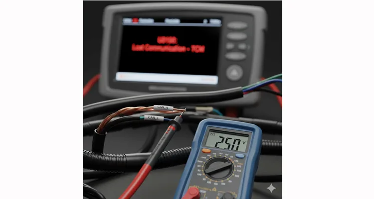
You know the scenario. A modern truck or SUV arrives, its instrument cluster a festival of warning lights. The scanner connects, but throws a timeout trying to reach the TCM. The ECM responds, but with a list of lost communication errors from its peers. The patterns are familiar:
- Intermittent or complete loss of communication with one or several ECUs, often temperature or vibration-dependent. (For deeper analysis, see our guide on diagnosing intermittent CAN bus failures).
- Plausibility errors across different systems, where sensors sharing data via the CAN bus report conflicting, impossible values.
- A vehicle defaulting to a limp-home mode, with faults that seem logically disconnected.
- The scan tool simply showing “No Communication” for critical modules like the ABS or Transmission Control (common causes are detailed in this fleet manager’s guide to OBD2 port issues).
The knee-jerk reaction is to blame the quietest ECU. However, based on two decades of factory-level engineering and resolving field failures, the ECU itself is at fault less than 50% of the time. The failure is almost invariably in the network’s infrastructure—the CAN bus wiring and its foundational electrical health.
The Core of the Issue: Decoding the Differential Dialogue
To troubleshoot effectively, you need to know what your multimeter is actually interpreting. A CAN bus is a conversation, not a monologue. It relies on a differential signal between CAN High (CAN_H) and CAN Low (CAN_L). Imagine them as two voices in harmony.
- To say “0” (Dominant State), they oppose: CAN_H voice rises (to ~2.5V – 3.5V in a 12V system), while the CAN_L voice falls (to ~1.5V – 2.5V).
- To say “1” (Recessive State), they rest at the same neutral tone (~2.5V).
The receiving module listens only to the voltage difference between them. This design inherently rejects common noise. Your multimeter’s role is to verify this delicate electrical dialogue is intact. If both lines move in unison (voltages rise and fall together), the conversation is garbled, and data is lost.
The stability of this entire system rests on three pillars, each directly measurable:
- Proper Termination: A 120-ohm resistor at each physical end of the main network backbone. Without these, electrical signal reflections travel back, corrupting the data stream. (Understanding this is critical; learn more about what a missing 120-ohm terminator means).
- Continuity & Integrity: An unbroken path for both wires, isolated from shorts to each other, to power, or to chassis ground.
- Stable Reference Voltages: Every module requires a pristine ground and stable power supply. Noise or voltage offset on the ground reference directly poisons the differential signal it creates.
Failure in any one of these areas manifests as the confusing communication havoc on your scanner.
Step-by-Step: The Multimeter Diagnostic Protocol
Grab a reliable digital multimeter. We’ll progress logically from quick sanity checks to focused fault isolation.
Step 1: The Static Voltage Check – Capturing the Network’s Baseline (Ignition ON, Engine OFF)
With the ignition on but the engine off, the network is awake but idle. Measure from CAN_H to Ground, then CAN_L to Ground.
You’re assessing a baseline “resting” state. For a standard 12V High-Speed CAN (ISO 11898-2, the international standard for road vehicle controller area networks), expect:
- CAN_H: A steady 2.5V to 2.7V
- CAN_L: A steady 2.3V to 2.5V
Field Insight:
Don’t expect a perfect 2.500V. Each ECU’s internal reference has micro-tolerances. A reading like a constant 2.1V on one line is a red flag, but first, rule out parasitic loads. I once traced this exact reading on a Mercedes Actros to a cheap aftermarket GPS tracker spliced into the network. Always disconnect non-OEM devices before condemning the factory wiring.
- 0V: Indicates an open circuit or a catastrophically failed module transceiver pulling the line to ground.
- Battery Voltage (12V+): Clear sign of a short to power.
- Same Voltage on Both (e.g., 0.8V): High probability of a short between CAN_H and CAN_L.
Step 2: The Dynamic Voltage Check – Observing the Conversation (Engine RUNNING)
Start the engine. Now the network is active. Your multimeter’s display will become unstable—this is good. Observe the range of the fluctuations.
- CAN_H should oscillate between approximately 2.5V and 3.5V.
- CAN_L should oscillate between approximately 2.5V and 1.5V.
The Critical Pattern: They must move in opposite directions. When CAN_H peaks, CAN_L should be at its trough. If the numbers on both channels climb and fall together, the differential signal is non-existent, and the bus is electrically dead.
Step 3: The Terminal Resistance Check – The Network’s Vital Sign (Vehicle Power FULLY OFF)
This is non-negotiable. Disconnect the vehicle battery. At the Diagnostic Link Connector (DLC), measure the resistance between Pin 6 (CAN_H) and Pin 14 (CAN_L), the standard pins for High-Speed CAN on an OBD-II (J1962) port.
Your Target: ~60 Ohms.
Why 60? A properly terminated network has two 120-ohm resistors, one at each end, wired in parallel (120Ω // 120Ω = 60Ω).
Pro Tip:
Perform this test dynamically. Gently wiggle the harness near the DLC and at key junctions while watching the meter. If the value jumps erratically (e.g., from 55Ω to 65Ω), you’ve likely found an intermittent fault caused by poor pin tension or internal corrosion within a connector, not a faulty resistor. This is a core part of a complete CAN bus health check with a multimeter.
Interpreting the Reading:
- ~120Ω: One of the two terminating resistors is missing or open-circuited.
- ~40Ω: An extra, unintended 120Ω termination is present (often a faulty module with a shorted transceiver).
- 0Ω (Dead Short): A direct short between CAN_H and CAN_L.
- “OL” (Open Loop): Both terminators are open or the network backbone is physically broken.
Step 4: Isolation & Segmentation – The Systematic Hunt
If Step 3 reveals a fault (short, open, or incorrect resistance), you must locate it. Guessing is costly. Use the segmentation isolation test.
Methodically disconnect modular connectors or junction blocks in the middle of the suspected network segment. After each disconnection, re-measure the terminal resistance at the DLC. When your reading suddenly returns to the correct ~60Ω, the fault is contained in the harness segment or module you just isolated. This binary search method is exponentially faster than random probing.
The $8,000 Oversight: A Chain of Common Diagnostic Missteps
From our direct factory support cases, these interconnected errors represent the most costly pattern:
- The Live-Circuit Resistance Cascade: A technician measures resistance without disconnecting the battery. A bizarre reading prompts a “test” where 5V is applied to the CAN lines, instantly destroying the sensitive CAN transceivers in multiple ECUs. The Root Cause: A multimeter in Ohms mode applies a small internal voltage/current. On a powered network, this creates unpredictable paths and useless readings, tempting fatal “verification” steps.
- The “Clean Connector” Illusion: Visual inspection passes, but the fault persists. The culprit? Nearly transparent green insulating grease from assembly that, over years, facilitates corrosion on the inside of the female terminal barrel, only visible with a borescope camera. The Lesson: Corrosion is an electrical, not purely visual, fault. Pin tension and internal integrity are key, a lesson hard-learned in real-world cases of vibration and chemical corrosion.
- Overlooking Ground as a Signal Carrier: The system checks out until high-load circuits like headlights activate. The issue wasn’t the CAN wiring path, but a corroded ABS module ground strap on a fender well. The headlight current, finding a poor path, elevated the local ground potential, injecting noise directly into the module’s reference. The Fix: Always perform a voltage drop test on ECU grounds with the system under full electrical load.
How You Know You’ve Fixed It: The Validation Triad
A true repair is verified in three dimensions, not just one:
- Meter Verification: All static/dynamic voltages and the terminal resistance measurement are now stable and within the specified ranges, even when the harness is manipulated.
- Scanner Verification: All previously offline modules are present and communicating. Network-related DTCs (U-codes) clear and, crucially, do not return as “pending” or “current” after a key cycle.
- Operational Verification: The vehicle operates correctly on a road test, with no fault reoccurrence under specific stressors like vibration, heat soak, or high electrical load (standards that go beyond basic ISO vibration tests).
The Right Tools for a Robust Network: Why the Pathway Matters
A multimeter diagnoses the fault, but the repair’s permanence hinges on the components reinstated. Our philosophy is to engineer pathways, not just cables.
Consider a real case: We mandate climate-controlled storage for raw cable, a practice underscored by our commitment to environmental management systems like ISO 14001. This seemed procedural until a batch for Arctic mining trucks was briefly held in a standard warehouse. Subsequent insulation resistance tests detected elevated leakage. The cause? The polyethylene insulation had absorbed ambient moisture, altering its dielectric properties—a fault that would manifest as intermittent noise at extreme cold. In a controlled environment, this variable is eliminated. This depth of control is what defines an OEM-grade component, a mindset certified under IATF 16949.
This principle is baked into our OBD-II diagnostic cables and CAN bus interfaces. They are precision tools featuring matched-impedance wiring to preserve signal integrity (critical for effective EMI shielding), not generic adapters. Every connector undergoes a 100% tested protocol for continuity, insulation resistance, and correct pinout, following a zero-defect process akin to PPAP. Full-plastic, RoHS-compliant housings are used because under-hood longevity is assumed.
For those in fleet maintenance, working with specialty equipment, or integrating aftermarket systems into OEM networks, the standard off-the-shelf cable is often the weakest link. Our OEM customization service exists for this reason. We provide solutions with specific lengths, AWG gauges, jacket materials (oil-resistant, high-temp), and connector types to integrate seamlessly into demanding applications, whether for agricultural machinery, marine systems, or industrial automation. Often, the true cost of a custom cable is lower than the repeated downtime of a generic failure.
A Note on Diagnostic & Integration Hardware: The principles discussed here apply directly to the cables you use for diagnosis and system integration. Whether you need a basic breakout cable for probing, a right-angle connector for tight engine bays, or a custom OEM-grade harness for permanent installation, the integrity of that physical link is paramount. Inferior cables can introduce the very faults—resistance, noise, intermittency—that this guide teaches you to diagnose.
Frequently Asked Questions (Technical Briefs)
Q: I have perfect 2.5V/2.5V static voltage and 60Ω resistance, but the bus is inactive. What’s wrong?
A: You’ve confirmed the physical layer is healthy. The issue is likely in the network management logic. Many architectures (e.g., BMW, VW) require a specific wake-up message or signal from a sensor (like the Intelligent Battery Sensor) to activate the gateway module and bring the bus online. Your next step is to use an oscilloscope or deep-dive scanner to check for this activation sequence.
Q: Is a basic multimeter sufficient for CAN bus diagnosis?
A: For foundational checks—continuity, resistance, and static/dynamic voltage—yes, it will resolve the vast majority of physical layer faults. For diagnosing timing issues, EMI noise patterns, or subtle waveform distortions, an oscilloscope is required. The multimeter gets you 80% of the answer.
Q: The terminal resistance at the DLC reads 120Ω, not 60Ω. Is this acceptable?
A: No. This indicates one of the two essential 120-ohm terminating resistors is missing or open. The network will experience signal reflections, leading to intermittent communication errors that worsen with higher data rates or longer cable runs.
Q: What’s the most effective way to locate a short to ground on a CAN line?
A: The isolation method (Step 4) is the most reliable. For hard-to-access harnesses, a tone generator and amplifier probe can be incredibly effective for tracing a shorted wire through conduits and body panels by following the audible signal, a technique useful in complex forensic failure analysis.
Q: Are all CAN buses the same?
A: No. Key types include:
- High-Speed CAN (ISO 11898): Powertrain, Chassis; ~500 kb/s.
- Low-Speed/Fault-Tolerant CAN: Body control, comfort; ~125 kb/s.
- Single-Wire CAN (SWC): Legacy GM systems.
For a broader look at vehicle networks, see our comparison of J1708 vs J1939 and guide to legacy OBD2 protocols.
Q: Can one module kill the entire CAN bus?
A: Absolutely. If a module’s internal CAN transceiver fails in a shorted state, it can pull down both CAN_H and CAN_L lines, paralyzing the entire network. This is why the segmentation isolation test is so critical—it efficiently identifies the faulty node.
Q: How vital is maintaining the twist in CAN wire pairs during a repair?
A: Critical. The twist provides common-mode noise rejection. If you must repair a section, a proper connection is vital. We advocate for crimping over soldering for vibration reliability in such repairs, and strive to maintain the original twist rate. Never route CAN_H and CAN_L as separate, untwisted wires.
Q: Your emphasis on factory standards seems abstract. What’s the practical benefit for my repair?
A: The benefit is absolute predictability. 4-step quality inspection and climate-controlled logistics mean the cable or harness you install has no hidden flaws—no moisture absorption, cold solder joints (understanding cold weld failures), or off-spec wire that could fail after thermal cycling. It ensures your repair’s electrical performance matches the OEM’s original intent.
Diagnosing a CAN bus fault with a multimeter is foundational expertise. It demands patience, a rigid process, and respect for electrical principles. It distinguishes a lasting, professional repair from the expensive cycle of swapping expensive modules.
Stuck on a persistent network gremlin? Sometimes a fresh perspective or a custom-engineered cable solution is what’s needed to bridge the gap between a known problem and a reliable fix.
Need a 100% reliable interface for your diagnostic tool or a unique vehicle platform? Share your pinout, environmental specs (temperature, vibration, chemicals), and the specific fault symptoms. Our engineering team will analyze it as a diagnostic case study and propose a robust harness or adapter solution.
Contact us via our Contact Page for detailed engineering support, or reach out directly on WhatsApp to share photos of your OBD connector and fault codes. Let’s get your networks communicating reliably again.
