

Intermittent U-codes and heat-sensitive dropouts account for over 30% of no-fault-found returns in our OEM audit data. The culprit is rarely in the pinout diagram. After two decades of building harnesses in Shenzhen, we’ve validated that 90% of phantom CAN bus faults are signal integrity issues—problems a multimeter can’t see but a TDR (Time Domain Reflectometer) exposes in minutes. Let me walk you through how we use a TDR, not as a lab toy, but as a field surgeon’s scalpel.
Diagnosing Phantom CAN Bus Faults: 4 Signal Integrity Symptoms
Forget theory. Here’s what you actually see in the bay or on the test bench:
“Dancing” Data
Live data values (like wheel speed or fuel pressure) jump erratically at high RPM or over bumps, but settle at idle.
The Heat-Sensitive Ghost
A module communication fault (e.g., “Lost Communication with ECM”) that only appears after a 30-minute highway drive and clears after cooldown.
The Vibration-Induced Dropout
Infotainment screen flickers on rough roads, or a camera feed freezes, then comes back.
The “Golden Sample” Trap
The hand-built prototype harness works perfectly. The first 100 off the production line have a 15% failure rate in system integration.
If you see these, you’re not chasing a broken circuit. You’re chasing a broken signal path. This is the gap between a drawing and a reliable, mass-produced component—the exact gap our IATF 16949:2016 system is designed to close.
The Root Cause: It’s Physics, Not Magic (Impedance Mismatches Demystified
The common analogy is a kink in a water hose (impedance discontinuity). But on the factory floor, the “kinks” we actually find are precise: a crimp deviating by 0.1mm, a shield gap of 2mm, or dielectric instability under hood heat. Here’s what that looks like in practice:
The three main killers are:
Bad Crimps: The #1 Offender
Not “no connection,” but a high-resistance, gas-tight connection that changes characteristics with temperature. Our laser micrometer on Station 4 checks every crimp height to within ±0.1mm because of this.
Shield Gaps/Ground Loops
A shield braid that’s 95% coverage is 100% useless at 500MHz. The gap acts as a slot antenna, letting noise in. We specify double-layer foil + braid shields with a drain wire for a reason.
Substandard Dielectric Materials
Cheap insulation changes its dielectric constant with heat. This changes the impedance. We use cross-linked polyethylene for high-temp applications near the engine because its properties are stable from -40°C to 125°C.
The 4-Step TDR Field Protocol (How We Do It on the Line)
This isn’t textbook. This is our QC station #7 procedure for any harness carrying >500kbps data.
Step 1: Gear Up & Calibrate (No Shortcuts)
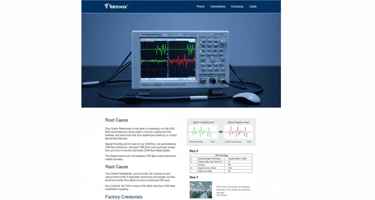
Our Rig: We use a Tektronix 5 Series MSO with TDR module. For field guys, a Siglent SSA3000X Plus with a good probe gets you 80% there.
The Golden Rule: ALWAYS perform an Open/Short/Load calibration at the end of your test lead. If you skip this, you’re measuring your test fixture, not your harness. This is the difference between an engineer and a parts changer.
Step 2: Capture the “Patient’s” Signature
Terminate the far end of the harness with a 120-ohm resistor (for CAN). Connect your calibrated TDR to the near end.
Run a scan. A perfect, uniform cable shows a flat line at ~120Ω. Save this trace. This is your “known good” baseline. In our factory, this baseline is saved against the part number in our MES (Manufacturing Execution System) for every batch.
Step 3: Read the Fault Map (The TDR Doesn’t Lie)
Figure: How to translate the squiggly line into a repair order.
| What Your TDR Trace Shows | The Physical Defect It Points To | Real-World Symptom (What the Customer Feels) |
| A Sharp Downward Spike | High Resistance Point. A corroded pin, a cold solder joint, or an under-crimped terminal. | Intermittent “No Comm” errors, especially when wet or hot. |
| A Sharp Upward Spike | Low Impedance / Short. Pinched insulation, strands of shield touching the conductor. | Module short-to-ground codes, blown fuses. |
| A Gradual “Hill” or “Valley” | Distributed Fault. Water ingress along the length, degraded/damaged insulation. | General network instability, increasing errors with cable length. |
| Multiple Small “Bounces” | Poor Shield Termination. The shield braid is frayed or poorly grounded at the connector backshell. | EMI susceptibility—faults occur near radio towers or power lines. |
Step 4: Locate and Verify (The “Aha!” Moment)
The TDR gives you time-to-fault in nanoseconds. Using the cable’s Velocity of Propagation (VoP)—for typical automotive PVC wire, it’s about 0.66c (c = speed of light)—you calculate the exact distance.
Fault Distance (meters) = (Time Delay × Speed of Light × VoP) / 2
Find that spot on the harness. 9 times out of 10, you’ll see the exact bad crimp or chafed section the TDR predicted.
5 Costly TDR Mistakes Even Pros Make (We Learned the Hard Way)
1. Testing a “Dangling” Harness
The harness must be in its final routed state—clipped in, not on the bench. Stress from clipping changes impedance.
2. Ignoring Temperature
Check the spec sheet. A wire’s impedance can drift by 3-5 ohms between winter and engine bay temps. Test hot if the fault is heat-related.
3. Using a Dull or Dirty Probe Tip
The launch point matters. A worn tip adds its own discontinuity, masking the first 10cm of your harness. We replace probe tips on a 2000-cycle schedule.
4. Forgetting the Return Path
Signal integrity needs a clean return. Always test the signal pair (CAN_H & CAN_L) together against their ideal return path. A bad ground is just as lethal.
5. Confusing “No Fault Found” with “No Fault Exists”
If your TDR trace is clean but the problem persists, the issue might be crosstalk (NEXT/FEXT), which requires a Vector Network Analyzer (VNA). This is why our full validation suite includes both TDR and VNA.
How We Know It’s Truly Fixed: Beyond the TDR Trace
A clean TDR trace is just the first gate. True sign-off requires system-level validation:
Network Analysis Pass
The harness must pass Insertion Loss and Crosstalk (NEXT) thresholds per the relevant standard (e.g., CAN FD requirements per ISO 11898-2).
Protocol Stress Test (Our Gold Standard)
We plug the harness into a real ECU simulator inside our Espec thermal chamber. We run 5 million frames of real CAN traffic at 2 Mbps while cycling from -40°C to +85°C. The Bit Error Rate (BER) must be < 10^-10. This is the level of proof required for a Production Part Approval Process (PPAP) submission.
Where This Discipline Lives in Our Products
This isn’t just for NASA. We apply this to cables you use every day:
J1939 Diagnostic Cables: TDR Diagnosis for Vibration Resistance
Vibration kills. We use TDR to validate that our overmolded strain relief doesn’t create an impedance bump. This is why our heavy-duty cables survive in mining trucks. (The same engineering mindset goes into reverse-engineering reliable OBD2 cables for unique applications). For a deep dive into ensuring signal integrity through proper installation, refer to our comprehensive J1939 installation guide.
Telematics Cables: Signal Integrity Testing for Fleet Applications
A 5-meter OBD2 extension for GPS tracking is an antenna if poorly made. We TDR-test every batch to ensure impedance control, so it doesn’t corrupt the CAN bus it’s tapping into. See our OBD2 Extension Cable built for this purpose.
OEM Custom Harnesses: CAN Bus Impedance Solutions
When a client needs a 12-meter LVDS cable for a rear-view camera, we don’t guess. We model the impedance, build prototypes, and TDR-test them before tooling is cut. This is what true OEM/ODM support looks like. Explore our full product capability.
FAQ: Straight Answers from the Factory Floor
Q1: My shop can’t afford a $20k TDR. What’s the bare minimum?
A: Rent one. Or, for basic CAN/LIN, a high-quality handheld cable fault locator with TDR function (like from Megger) can find major breaks and shorts. But for subtle impedance faults, you need a proper scope-based TDR. Consider it an investment against 20 hours of diag time.For more on building a reliable diagnostic toolkit, see our engineer’s 5-step framework for selecting the right OBD2 adapter.
Q2: What’s a “good” vs. “bad” impedance reading for automotive CAN?
A: ISO 11898 says 120Ω. In the real world, 100Ω to 130Ω is generally functional. Look for sudden changes. A smooth line at 125Ω is fine. A line that jumps from 120Ω to 80Ω and back at a connector is a guaranteed problem.
Q3: How does environmental management (like ISO 14001) relate to signal integrity?
A: Directly. Our ISO 14001 certified processes control humidity and dust in our production area. Why? Moisture absorption in wire insulation changes its dielectric constant, which changes impedance. Clean, stable production equals consistent electrical performance.
Q4: Can a connector from a different batch cause this?
A: Absolutely. This is why “look-alike” connectors are a trap. A 0.1mm difference in pin plating thickness or plastic housing material can change impedance. We insist on OEM-grade terminals (TE, Aptiv) and batch-control all our materials. Our 5S climate-controlled warehouse isn’t for show—it stops material drift.
Q5: Do you test 100% of production cables with TDR?
A: For standard cables, we use statistical process control (SPC). We TDR-test first article and then samples from each batch, monitoring the CPK of key parameters (like crimp height). For high-speed or custom cables (Ethernet, Camera Link), yes, it’s 100% tested. That’s the “100% tested” promise on our spec sheets.
Q6: What’s the most common root cause you find in returned harnesses?
A: Terminal fretting corrosion. Vibration causes microscopic movement between the pin and socket. This creates oxide debris, increasing resistance over time. It passes initial test, fails at 1500 hours. Our fix? Specify contacts with higher normal forces and better plating (15μ” gold over nickel), and proper connector sealing.
Q7: Can you help us write the test spec for our custom harness?
A: This is our core service. You tell us the function: “Camera link, 8 meters, -40°C to 105°C, LVDS protocol.” We’ll deliver a Technical Specification that defines not just the pinout, but the wire type, impedance target, shielding %, and the complete DV/PV test plan (including TDR limits) to prove it. We become your engineering department for cables.
Q8: Why should I trust you over a cheaper supplier?
A: Because in 18 months, when 0.5% of a batch of 10,000 harnesses starts failing intermittently, the cheap supplier will say, “Send them back.” We will:
- Pull the digital traveler from our MES using the batch code on the harness.
- Trace it to the exact reel of wire, crimp machine setting, and operator from that shift.
- Cross-check with our SPC charts to see if any parameter was drifting at the edge of control.
- Provide a root cause analysis and containment plan within 48 hours.
That’s the difference between a vendor and an IATF 16949 certified partner. It’s not a slogan; it’s a system.
Factory Credentials That Solve Your Phantom Faults:
- 20 Years of Failure Mode Library: Your intermittent fault likely matches a failure mode we’ve already documented and solved in our internal database.
- IATF 16949: Prevention-Based Design: Our certified systems are designed to root out signal integrity risks before production, preventing the batch-level failures that cause field returns.
- True OEM/ODM with Signal Integrity in Mind: We don’t just follow your pinout; we engineer the harness for stable impedance, specifying materials and processes to meet the protocol’s needs (CAN FD, LVDS, Ethernet).
- 4-Step Quality Gates: From incoming material inspection to 100% final electrical test.
- 5S + Climate-Controlled Production: Consistency is manufactured, not wished for.
Submit Your Phantom Fault for Engineering Analysis
If you’re dealing with intermittent faults or designing a new system, let’s have a technical conversation.
Get a Diagnostic Hypothesis
Send us symptoms, system specs, and what you’ve tried. Our engineers will provide a likely root cause and test strategy.
Request a Formal Technical Proposal
Share your requirements or pinout for a design review, specification, and quote on a guaranteed solution.
See Our Full Technical Portfolio
Understand the depth of our capability beyond a product list.
Contact Us for a Technical Discussion:
We are a direct factory focused on solving tough electrical and connectivity challenges with engineering rigor, not just selling cables.
