

For more than twenty years, our factory has operated in a space where most suppliers hesitate: taking a solitary, tangible OBD2 cable sample—devoid of any schematic, CAD file, or production notes—and engineering it into a fully certified, mass-producible assembly. The chasm between possessing a prototype and achieving reliable volume production isn’t crossed by imitation; it’s spanned through methodical forensic analysis and precision re-creation. This document outlines our exacting, six-stage methodology to convert your concept into a dependable, off-the-shelf product.
Reverse-Engineer Custom OBD2 Cables: When Your Project Starts with a Physical Sample
In the realms of automotive telematics, fleet management, and specialty vehicle diagnostics, development rarely begins with perfect drawings. More often, it starts with a tangible object and a pressing need. We regularly encounter scenarios like:
- Sustaining Legacy Vehicles: A dealership can no longer source a specific diagnostic cable for an aging but popular model. They have one fraying original and need 500 exact replacements to maintain their service fleet.
- Iterating on a Competitor’s Design: You’ve identified a commercial OBD2 splitter cable that fits your application, but its connector latch fails after fifty cycles. You seek a robust, brandable version manufactured to your revised specifications.
- Transitioning from Prototype to Production: A design engineer has crafted a functional one-off cable for a new data logger. It validates the concept but utilizes hand-soldered connections and non-standard gauges, making it unsuitable for assembly line manufacture.
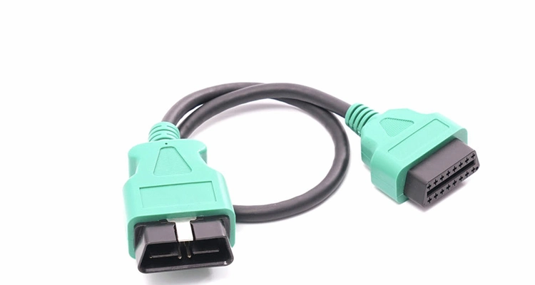
- Solving a Unique Integration Puzzle: A telematics provider needs a low-profile OBD2 Y-cable to fit an exceptionally tight port cavity in a new truck model, allowing simultaneous power and data draw for their hardware.For such space-constrained applications, a professional low-profile OBD2 cable is critical for ensuring reliable connectivity.
The common thread? The complete design intelligence resides solely within the physical artifact. Entrusting this to a conventional assembly house risks receiving a product that passes a cursory visual inspection but falters under electrical load, mechanical stress, or environmental extremes.
The Foundational Insight: A Sample is a Set of Answers; We Must Discover the Questions
Our approach is rooted in a lesson from our own history. Years ago, a client presented us with a telematics cable suffering persistent field failures. Our initial reproduction, visually and dimensionally identical, also failed. The root cause wasn’t the 24 AWG wire gauge we had matched, but the precise strand count and twist pitch of the conductors, which were engineered for minimal capacitance on a single-wire data line. This incident cemented our philosophy: true replication demands understanding the purpose behind every specification.
While a basic workshop may align wire colors and connector profiles, we interrogate the sample to decode its original design intent:
- Electrical Performance: What is the current requirement for each circuit? Does the sample employ specific shielding—foil, braid, or a combination—to mitigate engine bay electromagnetic interference (EMI) that could corrupt diagnostic data?
- Material Selection: Is the connector shell made of standard ABS or a glass-filled, heat-resistant polymer like PBT? What is the thickness and composition (e.g., tin or selective gold flash) of the terminal plating to ensure conductivity and corrosion resistance?
- Mechanical & Certification Compliance: How is strain relief implemented at the cable exit? What is the required engagement force for the latch to guarantee secure mating over thousands of cycles? Do all materials meet the stringent requirements of IATF 16949 for automotive quality and global directives like RoHS and REACH?
Overlooking these subtleties is the direct path to premature product returns and damaged reputations. Our systematic process exists to eliminate that risk.
Our Documented 6-Stage Workflow: From Your Prototype to Certified Production
This is our established, transparent engineering pathway to transform your sample into a verified, production-ready cable assembly.
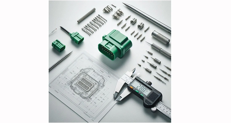
Stage 1: Forensic Analysis of Your Custom OBD2 Cable Sample
Your sample arrives at our controlled inspection laboratory
- Comprehensive Visual Cataloging: We capture high-resolution images from all angles under consistent lighting, documenting mold markings, wear patterns, and brand identifiers.
- Dimensional Metrology: Using digital calipers, optical comparators, and pin gauges, we create a detailed dimensional map covering housing geometry, pin pitch, latch design, and cable diameter.
- Material Characterization: Initial non-destructive tests help identify base polymer families and metal alloys.
Engineering Insight: Subtle mold flash lines or ejector pin marks can reveal the original manufacturing process, guiding our own tooling design for fidelity.
Stage 2: Controlled Deconstruction & Schematic Recovery
With client authorization, we perform a meticulous dissection to reveal internal architecture.
- Circuit Pathway & Pin-Out Mapping: Every conductor is traced from its terminal pin to its endpoint. We create a master pin-out diagram, cross-referencing it with the SAE J1962 standard while noting any proprietary protocol deviations (e.g., for manufacturer-specific diagnostics). (View the official SAE International standard)
- Componentized Bill of Materials (BOM): We disassemble and catalog every discrete element: connector housings, terminal types, precise wire gauge (AWG), shielding composition and coverage percentage, overmold material, etc.
- Shielding & Internal Layout Analysis: We examine any internal printed circuit boards (PCBs) and deconstruct the shielding approach—whether it’s a foil wrap, a braided sleeve, a combination, or a served shield.
Stage 3: Specification Lock & Proactive Validation
We transition from observation to active engineering and validation.
- Approved Component Sourcing: Our procurement team, leveraging a vetted supply chain, sources direct-equivalent or superior-grade components (e.g., terminals from TE Connectivity, Molex). All critical items are submitted for your formal approval.
- Definitive Engineering Documentation: Our CAD engineers generate detailed 2D drawings and 3D models for any custom parts, such as injection-molded connector bodies or overmolds. These documents specify all critical dimensions, geometric tolerances (GD&T), and material callouts.
- Test Protocol Development: Based on the cable’s application—from simple power delivery to high-speed CAN bus communication for ECU programming—we draft a comprehensive Quality Control Plan (QCP) detailing all validation tests.
Stage 4: Prototype Fabrication & Custom Tooling Development
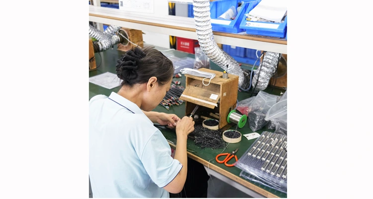
This phase marks the shift from digital model to physical part, centered on our core competency.
- Functional Prototyping: For bespoke connector designs, we employ CNC machining or high-resolution 3D printing to produce working prototypes for form, fit, and initial function testing.
- Precision Mold Engineering: Upon prototype approval, our in-house tooling designers engineer the production-grade injection mold. We optimize gate design to minimize stress, cooling channel layout for cycle efficiency, and venting to prevent air traps, ensuring part consistency.
- First Article Inspection (FAI): The initial shots from the new mold undergo a rigorous FAI, with every feature measured against the master sample and engineering drawings.
Stage 5: Pilot Run & Exhaustive Design Validation
We commit to volume only after the design is empirically proven.
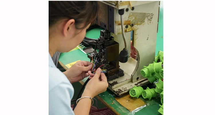
- Limited Pilot Production: A batch of 50-100 units is assembled on our production line using the finalized components and processes.
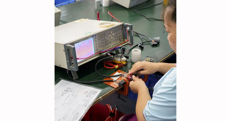
- Laboratory Design Verification Testing (DVT): This pilot batch is subjected to a battery of tests that surpass our routine 4-step quality inspection:
- Electrical Validation: Continuity, hipot (dielectric withstand), insulation resistance
- Mechanical Durability: Insertion/withdrawal force per USCAR-2 standards, cable flex and pull tests, latch cycle life testing.
- Environmental Stress Screening: Thermal cycling (e.g., -40°C to +105°C), humidity exposure, fluid resistance.
- Functional Performance: Signal integrity and ISO 11898 CAN bus compliance testing on active vehicle network simulators.
Stage 6: Scalable Production Under IATF 16949 Governance
Following your approval of the pilot batch, we initiate full-scale, controlled manufacturing.
- Process Validation & Control Plans: Every manufacturing step is validated for stability and repeatability. Control plans define inspection points and methods.
- In-Line Statistical Process Control (SPC): Production incorporates real-time checks for crimp pull force, visual defects, and 100% electrical function testing for shorts and opens.
- Traceable Packing & Dispatch: Finished cable assemblies are packaged per your specifications, including custom branding, in our climate-controlled warehouse to prevent material degradation before shipment.
The Partnership Distinction: Systems, Standards, and Shared Success
Selecting a manufacturing partner is a decision about their underlying quality ecosystem. Below is how our foundational systems translate into direct advantages for your project.
| Deminision | Conventional Cable Assembler | Shenzhen Carsun Electronic Technology | Your Tangible Advantage |
| Quality Management | Reactive; often limited to ISO 9001. | Proactive; IATF 16949:2016 certified with integrated ISO 9001 and ISO 14001 systems. | Prevention-based culture. Advanced Product Quality Planning (APQP) and Production Part Approval Process (PPAP) minimize launch risk. |
| Engineering & Tooling | Tooling is typically outsourced. Design is often cosmetic. | Fully in-house mold design and fabrication. Engineering focuses on design-for-manufacture (DFM) and root-cause analysis. | Direct control, faster turn. No third-party delays. IP security and seamless communication between design and tooling teams. |
| Business Model | Factory retains tooling IP. Client is a transactional customer. | Client retains intellectual property (IP) for custom tooling. We operate as a dedicated extension of your supply chain. | Long-term asset ownership. Guaranteed future supply without requalification or retooling fees. |
| Project Deliverables | Final product only. | Product + Full Technical Dossier (Approved BOM, 2D/3D drawings, DVT reports, material certifications, compliance docs). | Complete audit trail. Simplifies your own quality audits, future engineering changes, and second-source qualification. |
| Operational Integrity | Standard storage facilities. | Climate and humidity-controlled warehousing for all sensitive components and finished goods. | Supply chain resilience. Protects material properties (e.g., connector warpage, moisture absorption) from receipt to shipment. |
Our Commitment Pillars:
- Certified Process Rigor: Manufacturing within the IATF 16949 governed by the International Automotive Task Force framework mandates evidence-based decision making and continuous improvement, moving far beyond final inspection.
- Applied Engineering Experience: Over 20 years of focused automotive cable manufacturing has built a knowledge base that anticipates issues in material compatibility, mold flow, and end-use application.
- Transparent Collaboration: We view projects as partnerships. You receive milestone updates and have visibility into the process, ensuring alignment from initial analysis through production ramp-up.
Navigating Complexity: 5 Critical Pitfalls in OBD2 Cable Reverse-Engineering
The difference between a working prototype and a reliable product often hinges on avoiding these subtleties.
| Pitfall | Our Mitigation |
| Pitfall: Presuming Appearance Equals Function. Reproducing the wire routing but overlooking the engineered impedance control via specific shield termination or conductor twist. | Our Mitigation: We employ Time Domain Reflectometry (TDR) testing where applicable to characterize the sample’s impedance profile, ensuring our replication maintains signal integrity for sensitive operations like ECU flashing over CAN FD networks. |
| Pitfall: Cost-Driven Material Degradation. Substituting a generic, non-automotive grade plastic (like standard PVC) for an engineered material (like cross-linked polyethylene, XLPE) in under-hood applications. | Our Mitigation: Our material analysis includes verifying polymer type and temperature rating. We advocate for—and source—materials that meet the original environmental specifications, not just mimic appearance. |
| Pitfall: Neglecting Connector Tribology. Failing to specify the correct terminal plating thickness or spring alloy, leading to high insertion force, fretting corrosion, and intermittent electrical contact. | Our Mitigation: We measure and specify terminal spring forces and plating requirements (e.g., 0.76µm tin over nickel) to ensure low, stable contact resistance over the product’s required mating cycle life. |
| Pitfall: Blind Trust in Standard Pinouts. Assuming the sample follows the baseline SAE J1962 pinout, when it may repurpose pins for a manufacturer’s proprietary diagnostic protocol (e.g., BMW’s K-Line on pin 7) or dedicated power feeds. | Our Mitigation: Our pin-out analysis is exhaustive and agnostic. We map function, not just continuity, identifying all active and reserved pins to create a true functional schematic. |
| Pitfall: Underestimating the Vehicle Environment. Validating function only at room temperature, ignoring the effects of thermal expansion, vibration-induced fatigue, or exposure to automotive fluids. | Our Mitigation: Our Design Verification Testing protocol subjects pilot samples to combined environmental stresses, simulating real-world aging to uncover failure modes before mass production. |
Defining Success: Measurable Outcomes for Your Custom Cable Project
A successful engagement with our team yields unambiguous, verifiable results:
- Validated Performance: Production units meet or exceed all functional parameters of the original sample, with stable data transmission and protocol compliance.
- Guaranteed Physical Compatibility: Connectors engage fully and securely with the target vehicle’s OBD2 port and mating device, with tactile and auditory confirmation of latchin
- Complete Technical Documentation: You are provided with a comprehensive digital package for the product, including the approved BOM, manufacturing drawings, full test reports, and certificates of conformity (CE, RoHS, REACH).
- Demonstrated Production Stability: Statistical data from in-process checks and lot-to-lay testing confirms the manufacturing process is capable and in control.
- Field Reliability: The cables perform as specified in their end-use application, resulting in zero failures attributable to manufacturing or design defects.
- Scalable for Telematics: Whether replicating a simple diagnostic cable or a complex J1962 OBD2 GPS tracker cable requiring constant power and data, our process ensures reliable performance in the target application.
Frequently Asked Questions: The Reverse-Engineering Process Clarified
Q1: What initiates the reverse-engineering process?
A1: The process begins optimally with 1-2 physical samples. Supplemental information regarding the cable’s application (specific vehicle make/model, compatible diagnostic tool, known failure modes) significantly accelerates our initial analysis. You can submit details and images through our Contact Page.
Q2: What is the typical timeline from sample receipt to production?
A2: For a cable utilizing entirely standard, off-the-shelf connectors, the process typically requires 4-6 weeks for replication and pilot validation. Projects necessitating fully custom, injection-molded connectors require 10-14 weeks, with the majority of that time dedicated to precision mold design, fabrication, and sampling.
Q3: What are the ownership rights for the custom tooling (molds)?
A3: In a standard engagement, you retain full intellectual property (IP) rights to the custom tooling and the product design. We act as your contracted manufacturing partner, housing and maintaining the tools for your exclusive use, ensuring long-term supply chain security.
Q4: Can you enhance the original sample’s design during replication?
A4: Absolutely. A key part of our Stage 3 validation is identifying potential improvements. We routinely provide Engineering Change Proposals (ECPs) for client approval, such as upgrading to a higher-temperature insulator, adding enhanced EMI shielding, or improving strain relief geometry.
Q5: What are your minimum order quantities (MOQs)?
A5: MOQs are project-dependent. For assemblies using existing connector inventories, MOQs can start at 500-1,000 units. For products requiring new, custom molds, the MOQ is calculated to responsibly amortize the one-time tooling investment, and we work collaboratively to establish a volume that aligns with your business needs.
Q6: How is consistent quality ensured during high-volume production?
A6: Quality is engineered into the process via our IATF 16949 system. This mandates Statistical Process Control (SPC), layered audits, and a focus on prevention. Every production batch undergoes our stringent 4-step quality inspection, and we provide supporting data upon request.
Q7: Do you manage end-product compliance and certification?
A7: Yes. As the manufacturer of record, we can generate the necessary technical documentation and coordinate with accredited third-party laboratories to perform testing for global market access, including declarations of conformity for CE, UKCA, RoHS, and REACH.
Q8: Do you support full OEM/ODM customization beyond exact replication?
A8: Yes, comprehensive customization is our specialty. We offer complete OEM/ODM services, including custom laser etching of your logo, tailored packaging, specific cable lengths and jacket colors, and modifications to electrical specifications (such as increased AWG for higher current).
Initiate Your Custom Manufacturing Project
If your requirement extends beyond a generic catalog item—if you need a partner capable of forensic analysis, rigorous validation, and precision manufacturing derived from a sample—our engineered process is your solution.
Choose “Request Feasibility Review” if:
You have photos of your sample and initial concepts, and want our engineers to assess the project‘s feasibility, timeline, and general direction.
Choose “Chat with Our Engineer” if:
You need to discuss technical details immediately, such as protocol compatibility (CAN, K-Line, etc.), operating temperature range, material selection, or specific cable specs (AWG, shielding requirements).
To Begin the Formal Analysis & Quotation Process: Contact us to receive our Sample Intake Protocol, which includes a pre-formatted questionnaire and instructions for sending your physical sample to our R&D facility.
Let‘s engineer your solution. We will provide a clear, phased roadmap to transform your sample into a validated, production-ready cable assembly. You are engaging not just a factory, but a qualified engineering and manufacturing partner.
