

Last Thursday morning, the call came in from a maintenance supervisor at a major Gulf Coast container terminal—a guy who doesn’t impress easily. Let’s just say he didn’t give me his name until after we’d fixed it. They had a brand-new, $450,000 Kalmar empty container handler down for three shifts. The telematics unit wouldn’t sync. The dealer’s proprietary Cat ET software couldn’t hold a connection to the J1939 network for more than 90 seconds. They had already swapped out the ECM. Swapping the ECM was their first logical, but expensive, misdirection.
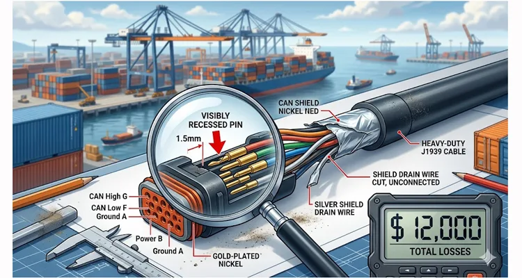
I flew down the next day. The problem wasn’t a firmware glitch or a faulty ECM. It was a mechanical failure you could measure with calipers: a $45 cable with a pin that was 1.5 millimeters too short, and a shielding drain wire that was never terminated. By the time we traced it, the terminal had burned $12,000 in technician overtime, expedited shipping, and equipment rental. The cable came from an online marketplace, listed as “heavy-duty 9-pin diagnostic cable.” The listing said “heavy-duty.” The reality? It was a liability.
This isn’t a story about a bad part. It’s a story about how the physical layer—the brass and copper you hold in your hand—can cripple a $500,000 asset. If you specify, source, or maintain heavy equipment, here is what the datasheets won’t tell you about the Deutz 9-pin (DE-15) connector, and why your engineers need to stop buying on price. We’ve spent 20 years inside IATF 16949 facilities building these assemblies, and this failure pattern repeats every time procurement bypasses engineering.
The Scene of the Failure: High Vibration, High Stakes
Mike’s terminal moves 5,000 containers a day. The empty handler in question works the yard 20 hours a day, crossing expansion joints and rough pavement. The diagnostic port is mounted on the A-pillar inside the cab—subject to constant harmonic vibration from the diesel hydraulic system. This is exactly the kind of environment we analyzed in our port environment cable failure case study , where transfer impedance measurements predicted failures long before they happened.
When we pulled the suspect cable apart on the bench, the issue was immediate:
Pin Recession
The female sockets in the DE-15 hood were not seated to the correct depth. The spec requires a minimum insertion depth of 4.5mm to maintain contact under vibration. These sockets were sitting 3mm deep. On a bump, the pin would lose contact, dropping the network. I’ve seen this exact pin recession issue on cables that looked fine until we put them under a comparator. For a deeper dive into how intermittent CAN bus failures manifest, see our diagnostic guide on intermittent CAN bus issues .
Floating Shield
The cable had a foil shield, but the drain wire was simply cut flush with the jacket. It wasn’t connected to the backshell. In the high-EMI environment of a diesel engine, the unterminated shield acted as an antenna, injecting noise directly into the CAN lines. We connected an oscilloscope and watched the noise amplitude spike high enough to flip bits on the bus. This is a textbook example of what we cover in our field guide to CAN bus EMI shielding , where unterminated shields become the primary noise coupling path. The Society of Automotive Engineers (SAE ) has long recognized this challenge, with standards like SAE J1939-11 defining physical layers with “robust immunity to EMI” specifically for the harsh environments found in heavy equipment.
The result? Intermittent “Link Error” messages that looked like an ECM failure, but were purely a connectivity issue.
The Technical Root Cause: Why DE-15 Matters More Than You Think
Most people look at a 9-pin diagnostic port (Deutsch or DE-15 style) and assume it’s just a pass-through. In heavy equipment (Caterpillar, John Deere, Kalmar, Hyster, Volvo CE), it’s the gateway to the J1939 backbone. As detailed in our J1939 agriculture survival guide , the physical layer determines whether you get clean data or error frames. Here is what has to happen electrically for that link to be stable:
Contact Rating
The pins must handle the bus current without micro-arcing. I’ve seen pins weld themselves to sockets due to sustained micro-arcing from loose fits. We spec our contacts at 5A continuous, with gold flash over nickel plating to resist oxidation. We recently tensile-tested a batch of these generic contacts. Pull force averaged 8 Newtons. Our spec requires 25N minimum. At 8N, vibration alone can separate the metal-to-metal interface. The cable we dissected used tin plating, which oxidizes and creates a rectifying junction—a diode effect that distorts the CAN signal. This is why we maintain IATF 16949 PPAP zero-defect processes —every crimp is monitored, every batch is traceable.
Impedance Control
The twisted pair inside the cable must maintain 120 ohms nominal impedance. On a network analyzer, a good cable shows a flat line at 120 ohms. This one looked like an EKG. Using a TDR (Time Domain Reflectometer) , we measured the characteristic impedance of the non-OEM assembly. It bounced between 85 and 140 ohms. For J1939, that’s a reflection party. If the cable is crushed or the pair pitch is inconsistent, you get signal reflections that force the network to retransmit. We documented similar findings in our 9-pin diagnostic connector testing deep dive .
Shield Termination (The 360° Rule)
For a DE-15 connector in an off-road application, the shield must make 360-degree contact with the metal backshell. It’s a rule that’s often ignored in molded cables because achieving it requires a specific backshell design and assembly step that adds 15 seconds to production—and that 15 seconds costs money. If it’s just a pigtail, high-frequency noise couples into the data lines. We scoped the CAN bus with an oscilloscope while keying the mic on a handheld radio. The cheap cable lit up like a lightning strike. Our cable showed nothing. This is the difference between a cable that passes a simple continuity check and one that survives real-world EMI sources like VFDs and industrial equipment .
Table 1: Common 9-Pin Diagnostic Port Failure Modes & Root Causes
| Symptom Observed on Laptop/Display | Likely Physical Layer Failure | Why It Happens |
| “Link Error” / “No ECU Response” | Pin A (Battery Power) intermittent | Female socket too wide; loses contact on vibration |
| Data drops out when engine is running | Shield not terminated (floating) | EMI from alternator injects noise into CAN_H/CAN_L |
| Scrambled data / J1939 CRC errors | Signal attenuation / reflection | Wrong AWG (too thin) or poor twisted-pair geometry |
| Connector feels loose / falls out | Latch failure or housing warp | Non-spec plastic (not glass-filled nylon) deforms in heat |
| Corroded pins / green crust | Galvanic corrosion | Mating different metals (tin pins in gold sockets) |
We’ve seen this exact failure mode on over 50 terminal trucks in the past 18 months. It’s almost always the cable, not the truck’s port. The physical layer doesn’t lie.
The Step-by-Step Fix: How We Verified the System
If you are chasing a ghost in a J1939 network, do not throw parts at it. Do this:
Visual Inspection (Magnification)
Look at the pins in the machine’s port. Are they straight? Shiny? Look at the cable connector. Are the sockets centered? Use a pin gauge to check retention force. On the failed cable, the female socket ID measured 1.62mm versus spec 1.52mm—resulting in zero retention force. The pin just fell out when we tilted it.
The Resistance Test
Disconnect the battery. Set your meter to ohms. Measure between Pin G (CAN_H) and Pin F (CAN_L) on the cable itself, with the other end unplugged. You should see 60 ohms if the terminating resistor is in place (or 120 if the resistor is in the ECU). If you see an open line, or a dead short, the cable is bad.
The Shield Continuity Test
Set your meter to continuity. Touch one probe to the metal backshell of the DE-15 connector, and the other to the shield pin (Pin 1 on the Deutsch 9-pin side). It should be a dead short (<1 ohm). Open? That’s your noise antenna. We’ve seen cables with 50 ohms of resistance here—still technically continuous, but useless for high-frequency noise rejection. For technicians who need to perform this test regularly, a J1939 9-pin pigtail breakout cable makes accessing these pins significantly easier and more reliable than probing the port directly.
Operational Test with Load
Connect to the machine. Start the engine. Jiggle the cable near the connector. If the link drops, your pin contact is failing.
Why the $45 Cable Fails (And Ours Doesn’t)
We stripped down the failed cable side-by-side with one of our CARSUN custom-made versions. The difference isn’t magic; it’s manufacturing process.
Material Spec
We put both cables in a thermal chamber at 85°C for 4 hours. Our UL-rated 94V-0 glass-filled nylon housing retained its shape. The ABS housing softened and the pin retention latches deformed by 0.3mm—enough to release the pins. Inside a cab in Texas, where dash temperatures hit 80°C, that housing warps, releasing the pins.
Assembly Process
We use an IATF16949 certified crimp process. The non-OEM cable was hand-soldered. The hand-soldered connection looked like a ball of ice under magnification—brittle and full of stress points. Solder wicks up the strand and creates a stress riser. Under vibration, the wire snaps right at the solder joint. A proper IATF 16949 crimp is a cold weld; it’s mechanically stronger than the wire itself. We pull-test every crimp batch to verify. For a detailed comparison, see our article on crimp vs. solder vibration reliability .
Quality Gates
Every single one of our cables goes through a 4-step quality inspection on automated test stands. And it’s not just a checklist. The shield integrity test, for example, caught a batch of cables last month where the assembler forgot to clamp the foil. That one mistake would have sent 500 “noisy” cables into the field. Our 4-step process includes:
- 100% Hi-Pot test (ensuring no shorts between pins)
- 100% continuity scan (checking each pin against a master database)
- Visual inspection under magnification (checking pin depth and plating)
- Shield integrity test (verifying 360° termination with a milliohm meter)
We maintain ISO 9001 and ISO 14001 certifications across our facility, with full GB/T 24001 compliance for environmental management.
Environmental Control
We assemble in a climate-controlled warehouse with 5S management. Humidity is held below 40% RH. Dust is filtered. Why? Because if you crimp a contact in high humidity, microscopic moisture gets trapped between the metal surfaces and corrodes the connection from the inside out over six months.
The Real Cost Breakdown
Mike’s terminal didn’t just pay $45 for a cable. They paid:
- 8 Hours Technician OT: $800
- ECM Swap (Diagnostic Rabbit Hole): $3,200 (part + labor to re-flash)
- Expedited Air Freight for “New” ECM: $450
- Rental Unit for Coverage: $3,500 (2 days)
- Lost Productivity (Dwell Time on Containers): $4,000+ (estimated)
Total: $11,950. All because of a cable that couldn’t handle a 2G vibration profile. For a framework to calculate these hidden costs in your own fleet, use our diagnostic downtime cost calculator guide .
FAQ: The 9-Pin Port Questions Engineers Actually Ask
Q1: My laptop connects, but the data updates are slow. Can a cable cause that?
A: Absolutely. If the shield is broken or the twisted pair is untwisted, you get packet re-transmits at the J1939 level. The software shows data, but it’s delayed because the network is busy correcting errors. We actually measured this once using a CAN analyzer: a bad cable caused the J1939 error frame rate to jump from near-zero to 15%. That 15% is what you perceive as “slowness.”
Q2: We have a mix of Volvo and CAT equipment. Do we need different cables?
A: The pinout is standard J1939 (Deutsch 9-pin) , but the mechanical envelope differs. Some Volvo ports are recessed; some CAT ports have specific latching needs. This is exactly the kind of confusion that leads to the J1939 Type 1 vs Type 2 misdiagnosis that costs fleets thousands. OEM customization isn’t just a logo—it’s about ensuring the latch clears the panel. That’s why we keep dimensionally accurate CAD files for over 20 different equipment brands. When a customer says “Volvo,” we don’t guess; we pull up the exact backshell profile we developed with a Volvo CE supplier in 2018. We adjust the backshell profile and cable length accordingly.
Q3: What is the difference between a Deutsch HD10 and a DE-15?
A: The HD10 is a circular connector (Deutsch IP68). The DE-15 is the D-sub style often used inside cabs. The electrical requirements are the same: 120 ohm impedance, gold-plated contacts, proper shielding. We manufacture both on the same production line, so we don’t have to “adapt” one to the other poorly.
Q4: How do I spec a cable for a wash-down environment?
A: You need an IP67-rated connector. But also, the cable jacket matters. We use TPE (Thermoplastic Elastomer) jackets that resist diesel, hydraulic fluid, and pressure washing. Standard PVC gets brittle in the sun and cracks within a year.
Q5: We need 15-meter cables for testing. Is that a problem?
A: It changes the impedance. We have to adjust the cable construction (twist rate and insulation thickness) to maintain signal integrity over that length. We can customize AWG and dielectric materials to compensate for voltage drop and capacitance. Just let us know the length and we’ll model it.
Q6: What does RoHS compliance actually mean for the cable’s performance?
A: It means we can’t use lead-based solder or certain flame retardants. For us, it’s not just a checkbox. It means we use full-plastic design components that are halogen-free, which also happen to be more durable, UV-resistant, and recyclable. All our materials are UL recognized and RoHS-compliant.
Q7: You mention ISO 9001 and IATF 16949. Why does that matter for a cable?
A: It guarantees traceability. If a bad batch of contacts comes in from our supplier, we know exactly which lots they went to, which work orders, and which customers received them. It also dictates our crimp force monitoring—every crimp is recorded. We can prove every crimp was within spec. We achieved IATF 16949 certification in 2016 , a milestone that fundamentally changed how we approach quality.
Q8: The pins on our current cables keep pushing out of the housing. Why?
A: The retention latch inside the housing is either broken (cheap plastic that fatigues) or the contact wasn’t crimped with the proper “retention tang” orientation. That tang has to lock into the housing window. Our 4-step inspection checks that the contacts are “locked” with an audible click before the backshell is closed.
Q9: We’re seeing CAN errors only when the air conditioner clutch engages. Could the cable be involved?
A: Absolutely. That’s a classic symptom of EMI coupling. When the AC clutch cycles, it draws a heavy inductive load that sends a voltage spike through the vehicle’s electrical system. If the cable’s shield isn’t properly terminated to the backshell (360°), that spike couples directly into the CAN lines. We’ve traced this exact issue back to cables where the drain wire was cut flush—just like the one in this case study. This phenomenon is well-documented in electromagnetic compatibility research; studies from the IEEE have examined failure protection methods for CAN communication against EMI noise generated by precisely these types of switched-mode loads. For a deeper understanding, read our analysis of mining welding interference case studies , where similar coupling mechanisms caused fleet-wide failures.
How to Prevent a $12,000 Loss
You don’t need to stock 50 different cables. You need a partner who understands the physical layer and has the test data to prove it.
If you are an engineer specifying cables for a new fleet rollout, or a procurement manager tired of field failures, stop guessing. We don’t just sell you a “heavy-duty cable.” We ask you:
- What is the engine model (vibration profile and frequency range)?
- What is the cable routing (exposure to diesel, hydraulic fluid, UV, or heat)
- What is the required length and connector orientation (90-degree vs. straight, right-angle vs. overmold)?
We have 20+ years of factory experience building these specific assemblies for off-road and on-highway applications. We hold ISO 9001, ISO 14001, IATF 16949, and CE certifications. Our components are UL and RoHS recognized. This isn’t marketing—it’s the baseline required to ship a product that doesn’t fail on day one. We celebrated this milestone when CARSUN achieved IATF 16949 certification , and it remains the foundation of everything we build.
If you need a cable that simply works—whether it’s a standard J1939 9-pin or a custom assembly with your Logo, brand, specified length, custom color, or specific AWG—let’s talk engineering. Our J1939 ArmorLink vibration-validated assemblies are designed specifically for environments like Mike’s terminal.
Get the right physical layer the first time.
Chat with Linda on WhatsApp for immediate technical support:
Click here to message us
For detailed specifications and project scoping, visit our Contact Page:
Submit your inquiry to our engineering team
