

The failure report landed in our engineering queue as a PDF attachment: 18 months of maintenance logs from a Pacific Coast terminal operator. The pattern was unmistakable—a specific “heavy-duty, shielded” OBD2 extension cable model was failing at 30% between months five and seven of deployment. Intermittent connection loss. CAN bus errors.
The maintenance supervisor wanted to know why. More importantly, he wanted to know what specification changes would prevent recurrence.
We asked him to send the failed units to our lab in Shenzhen. This is what our dissection revealed, and why a “shielded” cable isn’t always a protected cable in actual service conditions.
The Environment: Measured Stress Vectors
Before we cut into the cable jacket, let’s define the environment using actual measurements. Over the past two decades of supplying cables to marine terminals, we’ve quantified the specific stress vectors that standard automotive cables aren’t designed to withstand:
| Stress Vector | Measured Parameter | Typical Automotive Spec | Port Environment Reality |
| Electrical Noise | Broadband EMI (100kHz-1GHz) | Intermittent exposure | Continuous 24/7 |
| Mechanical Vibration | RMS acceleration | 1-2g | 3-8g from diesel idle |
| Corrosive Agents | Salt deposition rate | 0μg/cm²/day | 15-50μg/cm²/day |
Standard automotive diagnostic cables, even those with basic foil shielding, aren’t designed for this environment. They’re designed for a climate-controlled service bay with intermittent use. The primary culprits—variable frequency drives on cranes and constant radio traffic—create the kind of broadband electromagnetic interference that demands robust shielding strategies, as detailed in our guide to EMI sources and CAN bus diagnostics.
The Teardown: What the X-Ray Vision and the Cutters Revealed
We started with a visual inspection, then moved to the X-ray (to see internal geometry without destruction), and finally, the cutters and the microscope.
What the dissection revealed, in sequence:
Failure Mode 1: Contact Interface Degradation
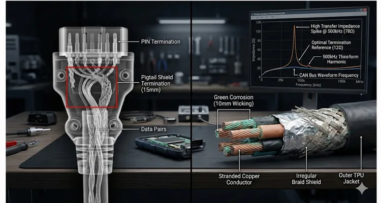
Primary evidence: Fretting corrosion on J1962 pins
Under the microscope, the J1962 connector pins showed clear signs of fretting corrosion—small amplitude oscillatory movement between the pin and the mating socket in the vehicle’s port. This was accelerated by vibration from idling diesel engines and the constant plug/unplug cycles during daily health checks. The tin plating had worn through in spots, allowing a corrosive film to build up on the base copper alloy. This increased contact resistance from 150mΩ when new to 2.4Ω at failure, starving the diagnostic tool of clean voltage.
Failure Mode 2: Shield Termination Geometry
*Primary evidence: 15mm pigtail measured on X-ray*
This is where the “shielded” claim fell apart in our lab.
We cut the overmold at the back of the connector. Underneath, the braided shield was gathered into a “pigtail”—a long, twisted bundle of wires—that was crimped to a single pin.
We measured the transfer impedance of the failed cable’s pigtail termination using a 100kHz-10MHz injection probe (per IEC 62153-4-15), the same test we run on every new cable design in our 4-step quality inspection process. At 500kHz—the third harmonic of a 250kbps CAN waveform—the pigtail exhibited 78Ω of transfer impedance. A 360° terminated shield of identical braid material measured 12Ω under the same test. The difference explains why this cable radiated 18dB more noise at the CAN transceiver input than our reference design. The X-ray confirmed the poor geometry: the shield was terminated nearly 15mm away from where the data lines exited the connector body. This fundamental error in shield termination is a common theme we address in our comprehensive CAN bus shielding and filtering guide.
Failure Mode 3: Grounding Topology Error
Primary evidence: Continuity between shield and signal ground
The design used the shield as the ground return path for the diagnostic tool. This is a fundamental mistake we see frequently in low-cost imports. Because the vehicle chassis and the diagnostic tool (plugged into a different power source) had different ground potentials, current was constantly flowing through the shield braid. This turned the shield into a heating element of sorts, and more importantly, created a massive radiating loop for low-frequency magnetic fields. It was a ground loop, literally cooked into the cable design.
Failure Mode 4: Moisture Ingress Pathway
Primary evidence: Green corrosion 10mm inside insulation
We dissected the wires at the point where they entered the connector. The insulation on the individual conductors showed signs of “wicking”—green corrosion traveling underneath the insulation from the cut end. The manufacturer hadn’t properly sealed the wire ends before termination. Salt-laden moisture entered the tiny gap between the conductor and the insulation, traveled up the wire, and corroded it from the inside out. The break wasn’t at the crimp; it was 10mm inside the cable jacket, invisible to any visual inspection. This type of internal failure, hidden from view, mirrors cases we’ve documented in our forensic guide to reefer wiring harness failure.
The Root Cause: A Breakdown of Engineering Compromises
The failure wasn’t one thing. It was a cascade of poor engineering choices that were invisible on a spec sheet but obvious under our lab equipment.
| Failure Point | Symptom | Measured Parameter | Root Engineering Cause | Industry Standard Gap |
| Pin Contact | Intermittent signal, high resistance | Contact resistance: 150mΩ (new), 2.4Ω (failed) | Tin plating worn through after 47 mating cycles | SAE J1962 specifies 1500 cycles in controlled lab, not industrial |
| Shield Termination | CAN bus errors, EMI susceptibility | Transfer impedance: 78Ω at 500kHz | Long pigtail termination; high impedance at high frequency | No industrial EMI requirement in typical cable specs |
| Grounding Scheme | Data corruption, noise on signal lines | Shield-to-ground continuity present at both ends | Using shield as ground return; created ground loop | No grounding topology verification in standard tests |
| Wire Seal | Internal conductor corrosion, “wicking” | Corrosion migration: 10mm inside jacket | No waterproofing at termination; capillary ingress | No wick test required for “automotive” cables |
The Solution: Specifying a Cable That Survives the Port
Based on this failure analysis, we revised our internal design specification for marine-terminal applications at our ISO 9001 and IATF 16949 certified facility. The current revision (Rev 4.2, dated 2024-03-15) requires:
1. Termination Geometry Verification
- Maximum pigtail length: 0mm (360° ferrule required)
- Verification method: X-ray sampling of first article, every 500 units
- Acceptance criteria: Braid clamped directly to conductive backshell at cable entry
2. Grounding Strategy: Isolate and Protect
- Shield-to-signal-ground isolation: >10MΩ at 50VDC
- Test point: Tool-end shell to pins 4 and 5
- Shield connected to chassis ground at vehicle side only
3. Environmental Sealing Validation
- Wick test: 24hr saline immersion, cut-end inspection
- Acceptance criteria: 0mm corrosion migration
- Epoxy back-filling inside connector backshell after termination, before overmolding
4. Material Selection: Fight the Galvanics
- Selective hard gold plating on contact mating areas (minimum 0.76μm)
- Nickel underplating (1.27-2.54μm)
- Connector housing and cable jacket compatibility verification per ASTM G187
These specifications align with the principles outlined in our OEM engineer’s checklist for EMI-hardened diagnostic cables, which provides a broader framework for specifying cables in harsh environments.
How to Confirm Your Fix: A Simple Field Check
You can’t X-ray every cable. But from our 20+ years of factory experience, you can perform two simple checks on a new batch before deployment. When troubleshooting intermittent issues, understanding the difference between crimp vs. solder vibration reliability can also inform your inspection priorities.
The Continuity/Ground Loop Check: Use a multimeter. Check for continuity between the shield (the outer connector shell) at the tool end and the signal ground pins (pins 4 and 5 on J1962) . There should be NO continuity. If there is, the manufacturer has tied them together, and you will have ground loop problems in any industrial setting. This simple test can prevent the kind of elusive faults detailed in our guide on how to diagnose intermittent CAN bus failures.
The Microscope Test: Look at the connector pins under 10x magnification. Are they perfectly smooth and centered? Or do you see tooling marks, off-center pins, or uneven plating? The latter indicates poor quality control in the connector assembly, which leads to the fretting we saw after only 47 cycles.
Related Products: Built for the Environment, Not the Brochure
Based on this teardown, the conversation with the maintenance supervisor shifted from buying “a cable” to engineering a solution. We didn’t sell him a stock part. We discussed:
- Custom-Length, Fully-Potted J1939 and OBD2 Extensions: Using the OEM customization options (length, color, logo, AWG) to create a specific SKU for his terminal, with the epoxy sealing and 360° termination built in. This is now managed as a regular stock item from our climate-controlled warehouse. For a deeper look at how such solutions are validated, our J1939 ArmorLink vibration-validated cable assembly page details similar rigorous testing.
- Deutsch DT series connectors: Replacing the vulnerable standard J1962 connector on the cable with a more robust, environmentally sealed Deutsch DT or HDP series connector, with a short pigtail adapter to the vehicle’s port. This moves the high-wear connection point to a sealed industrial connector.
- J1939 90-degree right angle cables for tight-space installations where standard straight connectors experience additional strain.
FAQ: Questions from Engineers on the Waterfront
Q: We’re seeing random CAN bus errors only when the crane is lifting. We’ve tried three different “shielded” cables. What should we measure?
A: Based on your description, you’re likely seeing common-mode noise coupled through the shield-ground connection. Here’s what we’d measure in our lab: (1) Voltage between vehicle chassis and diagnostic tool ground during lift cycle, (2) Shield continuity to ground at both ends using a current clamp, (3) Transfer impedance of your current cable at 250kHz. If you send us a failed sample, we’ll run the full IEC 62153-4-15 suite and send you the measurement report within 5 business days. This scenario is precisely why we developed our industrial EMI shielding solutions for OBD2 and J1939 systems.
Q: A supplier claims their cable is “military-grade” shielded. What does that actually mean for CAN bus?
A: In our experience, “military-grade” is a marketing term, not a specification. MIL-DTL-38999 (for connectors) and MIL-STD-461 (for EMI) have specific requirements. Ask for the transfer impedance plot from 100kHz to 10MHz, measured per IEC 62153-4-15. If they can’t provide it, they haven’t tested it. We publish our transfer impedance data for all industrial-grade cables on request. For a practical example of how we validate performance against such claims, see our mining welding interference case study on J1939 shielding.
Q: Why did our diagnostic tool work fine for 5 months and then fail?
A: The failure mechanism is often cumulative, which is why our 4-step quality inspection focuses on process control rather than just end-of-line testing. Fretting corrosion builds resistance slowly. Moisture wicking takes time to travel. The ground loop heats the shield slightly, cycle by cycle, until a connection finally fractures. It’s a slow progression, not a sudden event. Understanding the physics of cold weld vibration arbitration helps explain why some connections hold up better than others under continuous stress.
Q: Can I just apply dielectric grease to the connector?
A: It helps with pin corrosion, but it doesn’t fix a poor shield termination or an internal ground loop. It’s a band-aid on the symptom, not a cure for the disease. We see this frequently in field returns—connectors full of grease, but the real failure is inside the cable where grease can’t reach.
Q: You mentioned IATF 16949. Why does automotive quality matter for a port?
A: IATF 16949 isn’t just for cars. In our 20+ years of factory experience, it’s the most stringent quality system for defect prevention in cable assembly. If a supplier holds that certification, it means their processes for crimp force monitoring, 100% testing, and traceability are robust enough for mission-critical applications. It’s a shorthand for “they know how to build a reliable electro-mechanical component” because they’ve been audited for it. Our IATF 16949 PPAP zero-defect cable process page explains how this translates to tangible reliability gains. We also maintain ISO 14001 certification, reflecting our commitment to environmentally responsible manufacturing.
Q: How do I spec the right AWG for a long OBD2 cable?
A: For a standard diagnostic tool over 3-5 meters, voltage drop on the power and ground pins (4 & 5) is the main concern. From our OEM customization work, we typically recommend moving from the standard 22 AWG to 20 AWG or even 18 AWG for the power/ground conductors, while keeping the signal pairs (6, 14 for CAN High/Low) at a controlled impedance. This is a core part of any custom design discussion. The true value of such custom engineering is explored in our analysis of the custom cable’s true cost, which goes beyond upfront pricing.
Q: Your blog mentioned a case study with arc-welding. Is that similar to crane noise?
A: The frequency content differs, but the principle is the same: massive, broad-spectrum electromagnetic interference. Arc welders generate noise from DC up into the MHz range. Variable frequency drives on cranes generate noise in a similar, damaging band. The shielding and grounding principles to combat both are identical, which is why our 360° terminated shield design works across both applications. Our field guide to CAN bus and EMI shielding provides a deeper technical dive into these principles.
Q: The failed cable said “100% tested.” How could it fail?
A: “100% tested” usually means a basic continuity and hi-pot test at the end of the line. It does not test for shield effectiveness, long-term corrosion resistance, or performance under vibration. It passes the “as-built” test, but fails the “six-months-in-service” test. Our 100% testing includes functional electrical tests, but more importantly, our process control under 5S management ensures the process that builds it is capable and controlled, preventing the defects that lead to early life failure. This distinction is critical—a point reinforced in our J1939 cable ELD compliance audit failure analysis, where similar “tested” cables failed in regulated service.
Q: My diagnostic tool sometimes loses connection when I wiggle the cable near the connector. Is that the cable?
A: Almost certainly. That symptom points to an internal fracture at the termination point—exactly the failure mode we documented here. The conductor has likely work-hardened and snapped inside the insulation, making intermittent contact only when bent a certain way. This is a classic example of why vibration validation, as discussed in our J1939 cable durability for agriculture engineering guide, is so important.
Q: We’re retrofitting older equipment with telematics. Do we need to worry about legacy protocols?
A: Yes. Many pieces of “off-highway” equipment from the early 2000s use J1939 or J1708, but some may have proprietary or legacy diagnostic links. A robust solution often requires a cable that can handle both modern CAN and older single-wire protocols. Our guide to legacy OBD2 protocols can help you identify what you’re dealing with and specify the right interface.
Engineering Summary & Next Steps
The failed cable examined in this teardown failed not because it was “cheap” or because the environment was “too harsh.” It failed because four specific engineering decisions—pigtail termination, shared shield-ground, unsealed wire ends, and tin plating—each contributed to a cascade that reached end-of-life at six months. This is a textbook example of why surface-level specifications are insufficient for demanding applications, a theme we explore in our J1939 cable agriculture survival guide.
For engineers specifying cables for similar environments, we maintain a technical library of failure analysis reports (NDA required) covering:
- Connector plating analysis (SEM/EDS)
- Transfer impedance measurements (IEC 62153-4-15)
- Wick test results by cable construction type
If you’re drafting a procurement spec for marine-terminal, mining, or heavy industrial equipment and want to avoid this failure mode, send your current cable specification or a failed sample to our engineering team. We’ll provide:
- A no-cost failure analysis on your failed cables
- A marked-up specification with recommended revisions
- Reference designs for 360° termination and environmental sealing
To initiate:
- WhatsApp: Share photos of your failed cable and connector (+86 173 0716 8662)
- Contact Page: Upload your specification or request a pre-paid shipping label for failure analysis samples
