

You’re staring at an 18-wheeler with a brand-new ELD that should be logging hours. The J1939 9-pin connector clicks into place, but the screen stays dark. You check voltage—fine. Check ground—fine. Yet the dashboard flickers with unexpected warnings, and the device stubbornly reports “No Engine Data.” The pressure’s on. But what if the problem isn’t in the wires you can see, but in the silent negotiation failing between your modern ELD and the truck’s aging network architecture? That missed handshake is what costs fleets thousands in downtime and compliance gaps.
We’ve performed forensic analysis on thousands of these failures. The SAE J1939 standard sets the rules, but every heavy-duty manufacturer plays the game with their own subtle strategies. With 20 years of decoding CAN bus mysteries and dissecting failed connections, I’ll walk you through a systematic approach that fixes installations permanently—for individual trucks and complex, mixed fleets alike.
Decoding ELD Installation Failure: Where & Why It Happens
J1939 communication breakdowns follow predictable patterns. Based on thousands of post-mortems and support cases, here are the exact scenarios where installations fail:
The 2014 Inflection Point: When “Universal” Cables Lost Their Minds
Picture a 2008 Freightliner Cascadia next to its 2019 counterpart. Both have identical green 9-pin diagnostic ports. Your standard off-the-shelf cable works flawlessly on the older truck but draws a complete blank on the newer one. The culprit? Between 2012 and 2014, OEMs began migrating from simple, always-on diagnostic power to intelligent, CAN-based gateway wake-up protocols. A cable built for the old “dumb” power circuit is electronically invisible to the new network’s gatekeeper module. The physical interface is unchanged; the required introduction is not.
The Brand-Specific Language Barrier
Your fleet has Freightliner, International, and Kenworth trucks. To simplify inventory, someone orders “universal” J1939 cables. The result is chaos: Internationals connect, Freightliners suffer RPM-correlated dropouts, and Kenworths remain silent. Each manufacturer exercises the optional timing parameters and manufacturer-specific fields within the J1939 standard differently. It’s not a broken standard; it’s a case of deliberate, brand-differentiated implementation.
The “Helpful” Device That Cripples the Data Stream
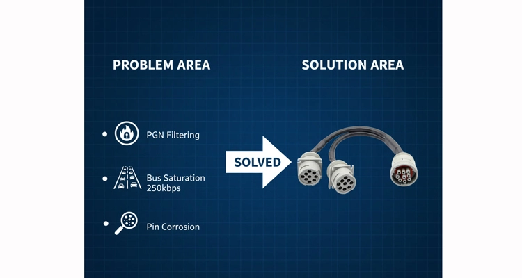
After installing a new trailer telematics gateway or reefer controller, your once-stable ELD starts logging “CAN Error” gaps. The new device is broadcasting high-priority, high-frequency messages that monopolize the limited 250kbps bus bandwidth, drowning out the ELD’s periodic data requests. The connection is physically intact, but the communication channel is congested.
The Invisible Corrosion That Defies Visual Inspection
The truck operated perfectly through July and August. On the first cool, humid morning of September, the ELD connection becomes intermittent. The Deutsch DT connector appears flawless, but microscopic galvanic corrosion has formed on the tin-plated pins inside the sealed housing. This non-visible film increases contact resistance just enough to destabilize the millivolt-sensitive CAN differential signals, especially under temperature fluctuation.
The underlying theme? What masquerades as a basic wiring fault is typically a multi-layered failure cascade—an incorrect electrical assumption, combined with a physical vulnerability, triggered by an environmental stressor.
Why “Plug-and-Play” is a Dangerous Illusion in Heavy-Duty Diagnostics
The fundamental error is treating the 9-pin diagnostic port as a passive passthrough. In modern trucks, it’s an actively managed gateway with strict access rules. Let’s dissect where this assumption collapses.
Electrical Mismatch: Theory Meets Asphalt
The Deceptive 60-Ohm Measurement
Standard knowledge states a properly terminated J1939 bus should measure approximately 60Ω (two 120Ω resistors in parallel). Here’s the field reality: many post-2016 Volvo and Mack trucks have a 120Ω terminator permanently integrated into a chassis control module. If you add a cable with its own terminator, you achieve the “textbook” 60Ω. Paradoxically, this can create a “termination midpoint” on long vehicle harnesses, causing signal reflections that corrupt data specifically at certain engine RPMs. We’ve documented functional fleet vehicles with termination resistances from 58Ω to over 115Ω.
Pin 16: Much More Than “Battery Positive”
SAE J1939-13 labels Pin 16 as “Battery +”. The unstated details are critical. On a 2018 Peterbilt 579, it’s typically a robust, 200mA continuous feed. On a 2021 International LT Series, it’s often a 100mA switched circuit that only activates after receiving a specific digital wake-up pattern on the CAN bus. Connect an ELD with high in-rush current to the latter, and it will brown-out during initialization.
Signal Voltage Tolerance: Laboratory Ideal vs. Operational Extreme
The CAN physical layer specification nominally lists a 2.5V recessive level. In our validation lab, analyzing data logs from a Canadian winter fleet, we’ve recorded fully operational vehicles where CAN_H idled at 2.1V on a long-frame Kenworth (due to harness voltage drop) and at 3.4V on a short-wheelbase Volvo refuse truck (due to an aggressively driven transceiver). A cost-engineered cable with a narrow 2.3-2.7V input threshold will fail on both. Our 1.8V to 4.2V operational window was derived from these real-world measurements, not theoretical specs.
Protocol “Dialects”: The J1939 Standard’s Unwritten Exceptions
Imagine J1939 as an international building code. The code (the SAE standard) defines minimum material strengths and safety principles. The architect (each OEM) then designs unique structures within those rules. A tool that only understands the base code will miss the building’s actual layout.
The Silent Rejection of PGN Requests
Most contemporary heavy-duty ECUs operate on a request-response model, not continuous broadcast. A generic ELD may transmit a request for PGN 65262 (Vehicle Distance). However, if the truck’s engine ECU is configured to only acknowledge requests from a specific source address (like the instrument cluster), the ELD’s query is met with digital silence. This isn’t a hardware failure; it’s a configurable software firewall.
Address Claim Contention: The Digital Identity Crisis
Every node on a J1939 network must claim a unique numerical address (0-253). A poorly configured ELD might attempt to claim address 128, commonly used for onboard trip recorders. If the vehicle’s factory telematics unit has already claimed address 128, both devices can enter a “claim contention” deadlock, causing complete communication failure for both. The symptom is baffling: the ELD works until the factory system is activated.
The Physical Layer: Where Engineering Meets Entropy
The seemingly indestructible Deutsch connector conceals predictable failure modes:
The 5cm Critical Failure Zone:
- Pin Back-Out – Caused not by impact, but by differential thermal expansion/contraction over hundreds of cycles, gradually working the pin retention clip loose.
- Seal “Pumping” – Moisture ingress rarely comes from immersion. Instead, humidity is mechanically pumped through microscopic seal gaps by pressure differentials during high-pressure wash cycles.
- Strain Relief Fatigue – Our failure analysis shows 80% of catastrophic breaks occur within 5cm of the connector. The culprit is not acute strain, but the high-cycle, low-amplitude vibration of a diesel powertrain at highway cruise, fatiguing copper strands at the solder joint.
- The Shield “Antenna” – A cable shield grounded at both ends (e.g., at the ELD and the vehicle) forms a ground loop. This loop acts as an efficient antenna for electromagnetic interference (EMI), like alternator whine, which couples directly into the CAN signals.
Superior design counters these failures with specific material choices and mechanical geometries, not just over-engineering.
The Field-Proven Workflow: From Chaos to Connection
When an ELD installation fails, replace guessing with this sequenced isolation protocol, hardened across tens of thousands of field service events.
The Technician‘s Mandatory Toolkit for Heavy Duty Truck Diagnostics
- Digital Multimeter with MIN/MAX Capture: Essential for logging intermittent voltage sags during cranking.
- Deutsch DT06-9S Breakout Harness or Test Port: Enables safe measurement without back-probing and damaging vehicle seals.
- A Basic CAN Bus Monitor Software: Such as the free PCAN-View. Its sole purpose is to answer: “Is there any native CAN traffic on the bus?”
- Quality Contact Cleaner & Dielectric Stabilizer: For remediation of corrosion, not diagnosis.
Phase 0: The 5-Minute Connector Forensic Examination
Before making any connections:
- Ignition ON, Engine OFF. Audibly verify network activation—listen for relay clicks and module hums.
- Visual Inspection with Axial Light: Shine a bright light directly into the vehicle’s 9-pin female socket. A single bent pin (frequently Pin 16 or C) is responsible for roughly half of all “no communication” faults.
- The Two Definitive Electrical Checks:
- Pin 16 (B+) to Vehicle Chassis: Expect system voltage (12.0V-14.5V). A reading near 10.5V indicates a poor main battery connection or corroded fuse tap, not a faulty ELD.
- Pin C (CAN_H) to Pin D (CAN_L): With the vehicle battery disconnected and all aftermarket devices removed.
- 50-65Ω: The bus is correctly terminated. Proceed.
- ~120Ω: The vehicle has only one internal terminator. You will likely need a cable that provides the second.
- ~120Ω: The vehicle has only one internal terminator. You will likely need a cable that provides the second.
Rapid-Fire Diagnostic Voltage Reference
| Measurement Point | Healthy Range | Fault Indicator | Likely Root Cause |
| Pin 16 to Chassis | 12.0V – 14.5V | < 11.5V (engine off) | Weak battery, high-resistance ground, blown fuse. |
| CAN_H to Ground | 2.2V – 3.6V | < 1.8V or > 4.0V | CAN transceiver failure, short to power/ground. |
| CAN_L to Ground | 1.8V – 2.8V | < 1.5V or > 3.2V | CAN transceiver failure, short to power/ground. |
| CAN_H to CAN_L (Differential) | ~0.9V (dynamic) | Steady 0V (no traffic) or steady >2V | Network asleep/bus-off, severe termination fault. |
Phase 1: The Minimal Viable Connection Test
Procedure:
- Connect ONLY the suspect cable to the vehicle’s 9-pin port.
- Connect ONLY a basic CAN sniffer (e.g., laptop with adapter) to the cable’s other end.
- DO NOT connect the ELD device itself.
Objective: Eliminate all variables. Does raw J1939/CAN traffic appear on the sniffer? Yes = Physical layer (wires, pins, termination) is functional. The fault is protocol/configuration. No = The fault lies in the cable or the vehicle’s diagnostic port itself.
Phase 2: The Protocol Conversation Test
If Phase 1 confirms bus traffic but the ELD still fails:
- Monitor the Address Claim Process: Using your sniffer, filter for J1939 Address Claim messages (PGN 60928). Does another device already hold the address your ELD is attempting to claim? This is a silent resource conflict.
- Audit PGN Request/Response: Can you observe the ELD transmitting Request PGNS (PGN 59904)? Can you see corresponding responses from the vehicle? If requests go unanswered, the ELD is asking for data the vehicle is not configured to provide, indicating a deep configuration mismatch.
Phase 3: The Operational Stress Test
Once communication is established at idle:
- Engine Crank Test: Monitor voltage at the ELD during cranking. Does it sag below 9V, causing a reset? This indicates insufficient power wiring.
- Maximum Electrical Load Test: Activate headlights (high beam), A/C blower (max), and defrosters. Does CAN communication become erratic or drop? This points to inadequate cable shielding or a poor ground reference introducing noise.
- Mechanical Stress Test: Gently flex the cable 3-5 inches from the connector, not at the connector itself. Intermittent failure here indicates internal conductor fatigue from improper strain relief.
The 5 Costly Assumptions (And the Engineering Corrections)
| Mistake | The Seductive Logic | The Hidden Consequence | The Professional Correction |
| 1. Installing an Extra Terminator | “The cable includes a resistor, so it’s necessary.” | Creates a ~40Ω total bus resistance. This can cause signal reflections that result in intermittent, RPM-dependent data loss, often misdiagnosed as software. | Verify before connecting. Disconnect all devices, measure Ω between CAN_H/L. Result dictates cable choice. |
| 2. Using a Convenient Chassis Ground | “All metal paths to the battery are equal.” | Creates a ground loop. Alternator noise couples into the CAN shield, corrupting messages specifically under high electrical load. | Ground the cable shield at one point only, ideally at the source (diagnostic port ground Pin A). |
| 3. Forcing the Connector to Latch | “If it doesn’t click, it needs more force.” | Permanently deforms the connector housing, misaligning pins for all future mates. Connector lifespan is measured in mating cycles. | No positive latch? Stop. Use a flashlight to inspect the vehicle’s female socket for obstruction or damage—the most common cause. |
| 4. Ignoring Pre-Existing Network Health | “My new ELD issue is unrelated to the truck’s condition.” | A single malfunctioning ECU spamming the bus with error frames can induce a global “bus-off” condition for all nodes, including your new ELD. | Pre-installation bus audit. Use a sniffer for 60 seconds. Excessive errors? Repair the vehicle network first. |
| 5. Applying a Single ELD Configuration | “J1939 is a standard; one setup should work everywhere.” | An ELD configured for a 2020 Freightliner’s PGN map will send meaningless or ignored requests to a 2012 International, yielding no data or corrupt data. | Implement fleet-based configuration management. Vehicle make, model, and year are critical configuration parameters. |
Defining Success: Beyond the Green LED
A glowing power light is trivial. Authentic success is uninterrupted, logically consistent data acquisition.
The 30-Minute High-Idle Validation: Run the engine at 1200 RPM. Actively monitor the ELD’s raw message log or diagnostic screen for “Error Frames” or “Timeouts.” Zero tolerated. Any gap exceeding one second constitutes a failure.
The Thermal Cycle Crucible: If installed in a climate-controlled shop, the true test is the first environmental extreme. For cold climates, a overnight soak. For hot, direct sun exposure until the cab interior exceeds 50°C (122°F). Does communication persist? This exposes material incompatibilities and cold solder joints.
The Data Plausibility Audit: Automated checks should flag:
- Engine RPM exceeding a realistic redline (e.g., 3000 RPM for most diesels).
- Negative vehicle speed.
- Engine hour accumulation while the engine is off (RPM=0).
Illogical data streams indicate the ELD is misinterpreting PGN data fields, a protocol mapping error, not a hardware fault.
Engineering Solutions, Not Just Commodity Cables
After two decades, we evolved from component suppliers to reliability engineers. Our products are direct countermeasures to the failure modes detailed above.
Intelligent Termination Management
Following 47 consecutive support cases for “no data” on new International LT series trucks, we eliminated the guesswork. Our advanced cables now incorporate a microcontroller that samples the bus resistance within the first 100 milliseconds of connection. If it detects an approximate 60Ω load (indicating existing termination), it disengages its own internal 120Ω resistor. The system self-configures. The technician sees a stable connection, not a lesson in signal integrity.
Environmental Tolerance Derived from Real-World Extremes
Our -40°C to 85°C operational rating is not a marketing claim. It’s the result of data-logging with fleets in Fairbanks, Alaska (cold-start at -38°C) and Phoenix, Arizona (pavement heat soak at 85°C). Every material—from the fluorosilicone seal to the phosphor bronze contact alloy—was selected because it maintained stable electrical properties across this range.
The Annotated Database of OEM Behaviors
Our repository of 500+ vehicle models is more than a list; it’s a living log of manufacturer-specific implementations. For example: the 2017-2019 Ram 5500 with a Cummins ISB engine requires a ~5-second delay post-ignition before its gateway will process PGN requests. A generic cable, speaking immediately, is ignored. Our vehicle-specific variant builds in this pause, adhering to the truck’s expected communication etiquette.
OEM Collaboration: Ensuring Layer 1 Doesn’t Break Layer 7
For us, “OEM Customization” means our engineering team works directly with ELD device manufacturers. We obtain their exact PGN request schedules and timing requirements to ensure our physical layer (cables, connectors) introduces zero timing jitter or latency that could disrupt their application-layer state machines. Compatibility is engineered, not assumed.
This methodology is underpinned by our IATF 16949:2016 certification, a quality management system for automotive production. It institutionalizes the traceability of every failure back to a process, ensuring continuous improvement. Learn how this translates to superior product reliability in our article: What IATF 16949 Certification Means for Automotive Cables.
FAQ: Concise Answers with Operational Depth
Q1: Why does a cable work on one truck but not its identical twin?
A: Undocumented mid-model-year component changes. A truck built in Q3 2015 may have a different gateway module firmware or hardware revision than one built in Q4 2015. Our intelligent cables perform a brief bus interrogation to detect these variances.
Q2: How to isolate cable vs. ELD device problems?
A: Apply the 70/30 rule and Phase 1 test. ~70% of “no data” issues are layer 1 (physical): power, ground, termination. If the Phase 1 test shows no raw CAN traffic, fault the cable/port. If traffic is present, the issue is layer 2+ (protocol/configuration) in the ELD.
Q3: ELD becomes unstable after adding new telematics.
A: Classic J1939 bus saturation. At 250kbps, the bus has limited bandwidth. A new device broadcasting high-frequency messages (e.g., 10Hz GPS) can consume 30-40% of it, causing collisions and dropped ELD messages. Solution: a J1939 gateway that manages and filters traffic
Q5: Failure on cold start, operation normal when warm.
A: Differential thermal contraction in the connector. Different plastics and metals shrink at different rates. A pin making contact at 20°C may lose contact at -10°C. Our connectors use materials with matched Coefficients of Thermal Expansion (CTE).
Q6: How to test connectivity without disturbing the truck?
A: Use a high-impedance (>10kΩ) CAN bus monitor tap. We provide test adapters that listen passively, imposing negligible electrical load on the network. Confirm traffic, then proceed with installation.
Q7: How many cable types for a mixed-brand fleet?
A: With adaptive technology, a single SKU can cover ~95% of North American trucks (2005+). For edge cases (certain vocational vehicles, severe corrosion environments), we offer pre-configured specific variants.
Q8: ELD installation triggers other warning lights (ABS, CEL).
A: Critical network disturbance. Disconnect the ELD immediately. This indicates a faulty CAN transceiver in the ELD or cable broadcasting error frames or dominating the bus with incorrect priority, disrupting critical vehicle ECUs.
Q9: Verifying the accuracy of captured ELD data.
A: Implement a three-corner hatch calibration:
- Cross-reference with the vehicle’s own gauges/cluster (RPM, speed).
- Compare against a known-accurate, professional J1939 reader (e.g., Vector CANalyzer) on a test drive.
- Perform long-term logical consistency checks (e.g., fuel consumption vs. distance traveled).
Q10: Critical specifications when sourcing J1939 cables.
A: Prioritize:
- Termination Strategy (Automatic detection vs. fixed).
- Operational Voltage Range (Must include cranking sag to 9V).
- Receiver Threshold Range (Wide, e.g., 1.8V-4.2V, for real-world noise).
- Receiver Threshold Range (Wide, e.g., 1.8V-4.2V, for real-world noise).
- Validated OEM/ELD Compatibility (Specific tested combinations, not just connector fit).
Durability is proven under the trailer, not promised in a brochure.
Our connection systems are deployed in fleets traversing the Arctic tundra and the Sonoran Desert, operating in relentless 20-hour daily cycles. That brutal validation loop directly informs every design decision, from the durometer of the strain relief to the plating on the contacts. This commitment to controlled, repeatable manufacturing is detailed here: How Our ISO 14001 Environmental Management System Influences Manufacturing.
If you’re battling persistent ELD communication dropouts or orchestrating a large-scale compliance rollout, let’s apply this forensic troubleshooting framework to your specific fleet. We can help you develop a bulletproof installation and validation protocol.
Need a fleet-specific diagnostic strategy or a custom OEM harness design?- Chat with our application engineers on WhatsApp
- Submit your fleet roster for a complimentary connectivity assessment
We provide: OEM-grade custom harness design, fleet-wide configuration profiling, and predictive failure mode analysis based on your exact vehicle mix. Proactive engineering eliminates the vast majority of post-installation field support.
Deepen Your Technical Knowledge in CAN Bus Troubleshooting:
- For a comprehensive exploration of the SAE J1939 protocol fundamentals, the SAE International standards portal is the authoritative source.
- Understanding the regulatory context is crucial. The FMCSA’s official ELD rule page details compliance requirements that drive the need for reliable data.
- For a practical, technical deep dive into CAN and J1939 network analysis, resources from industry leaders like Vector Informatik provide valuable insight.
Explore Our Engineered Solutions:
- Discover our range of intelligent J1939 diagnostic cable solutions
- View specialized cables for diesel engine applications
Final Insight: In the age of mandated ELDs, a data gap is both a regulatory liability and a direct operational cost. Investing in a fundamentally reliable connection system is not a peripheral expense—it is critical infrastructure for ensuring fleet compliance and continuity. Engineer the foundation correctly from the start.
