

We were three hours into a Thursday afternoon, the kind that bleeds into evening without asking. The client, a Tier 1 supplier out of Wolfsburg, was on speakerphone. Their brand-new ECU prototype, fresh off the assembly line, was sitting on our bench in Shenzhen. It was supposed to talk. It wasn’t saying a word.
The spec sheet clearly stated “KWP2000 compliant.” Our scanner was sending the wake-up pulses. The oscilloscope showed a clean 5V signal on the K-Line. By the book, it should have worked. But the “book”—in this case, ISO 14230-4—doesn’t always tell you what happens when the theory meets a cold solder joint or a misinterpreted keyword byte. The standard assumes ideal conditions. We don’t get those.
That afternoon, the issue wasn’t the protocol. It was the physical layer. In twenty years of building diagnostic cables, we’ve learned that when KWP2000 communication fails, it’s almost always the physical layer. The software thinks in ones and zeros. The wire lives in volts and amps. The mismatch between those two worlds is where troubleshooting goes to die.
The Handshake That Wasn’t: When 5 Baud Becomes 5 Problems
We had the pinout verified. We had power and ground. Yet the ECU sat there, dark and silent. We switched from the “fast init” attempt to the old-school 5 Baud initialization, hoping to brute-force a response. When fast init fails, 5 baud is your last resort before declaring the ECU dead.
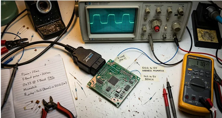
For the uninitiated, 5 Baud initialization feels like archaeology. You’re sending an address byte at 5 bits per second—literally pulsing the K-Line so slowly you can watch the relays click. Each bit takes 200 milliseconds. You can see the meter needle move. The ECU is supposed to respond with its “Key Word” bytes during this KWP2000 initialization phase.
We saw the address go out. We waited for the key bytes. Nothing came back.
We switched the scope to trigger on the falling edge of our transmission. There it was: a ghost. A mangled, low-voltage reflection coming back from the ECU’s transceiver, but it was too weak for the line driver to interpret as a logic high. The ECU was trying to talk, but its “voice” was barely a whisper. This is a classic K-Line communication failure symptom that has nothing to do with the protocol stack. The silicon was fine. The physics were broken.
The culprit? A mismatch in the pull-up resistance. The vehicle’s harness had a 510-ohm pull-up resistor to battery voltage. Our bench harness, built for speed and convenience, used a 1k ohm pull-up to a regulated 5V. The ECU’s transceiver was expecting the higher current from the lower resistance to swing the line. Because it couldn’t, it failed to generate a valid key byte during the KWP2000 initialization handshake. The difference between 510 and 1000 ohms doesn’t look like much on paper. On the wire, it’s the difference between communication and silence.
That key byte isn’t just a password. It’s the ECU’s ID card. It tells you the baud rate for subsequent communication (usually 10400 baud), the header format it wants (whether it expects addresses, length bytes), and the all-important timing parameters like P2min and P2max. If the physical layer is sick, that key byte never arrives healthy—and your KWP2000 diagnostic session never starts. You’re left staring at a timeout, blaming the wrong component.
The ISO 14230-1 Physical Layer: More Than Just a Wire
Most engineers treat the physical layer as a given. You connect pin 7 (K-Line) and pin 15 (L-Line, if you’re feeling retro) and expect magic. ISO 14230-1 defines it clearly, but the interpretation varies wildly between a 2002 Fiat and a 2012 BMW motorcycle. Getting KWP2000 over K-Line to work reliably means understanding what happens on the wire, not just in the software. The K-Line itself is a form of serial communication that dates back to earlier standards like ISO 9141, and its behavior on the bench can be deceptive. A clean signal on a lab scope means nothing if the vehicle’s alternator is dumping noise into the harness.
Here is where we see the most failures in the field, based on twenty years of building these cables in our Shenzhen facility, certified under IATF 16949, ISO 9001, and ISO 14001:
| Component | Specification | The “Golden Standard” (Our Shop Floor Rule) |
| K-Line Voltage | Vehicle battery voltage (Nominal 12V / 24V) | Must pass through the interface. Never clamp it to 5V TTL. We use components rated for 30V to survive 24V systems. We’ve seen what happens when a 12V-only transceiver meets a truck battery. It’s not pretty. |
| Idle State | High (Battery Voltage) | The line must be pulled high. If it floats, K-Line communication dies. We verify pull-up integrity on every cable because a floating line picks up noise like an antenna. |
| Pull-up Resistor | Typically 510Ω to 1kΩ | Match the vehicle’s expectation. When in doubt, use a lower value (510Ω) for better noise immunity on long K-Line runs. Higher resistance saves power. Lower resistance saves communication. We know which one matters more. |
| Baud Rate | 5 baud (init) / 10.4 kbaud (data) | Timing is loose, but line capacitance kills fast edges. We keep cable capacitance under 100pF/m to preserve signal integrity. That means choosing insulation materials carefully, not just grabbing whatever is cheap. |
| Wake-up Method | 5 Baud or Fast Init (120ms low) | Fast init is common on later models, but 5 Baud is the universal fallback for stubborn ECU communication. We design our cables to handle both because you never know what you’ll be connecting to. |
The mistake we see repeatedly? Engineers building cables with cheap CP2102 or FTDI chips and expecting them to bit-bang K-Line correctly. They forget the line needs to be open collector driven. You’re not driving the line high with a transistor; you’re letting a resistor do it. If your “K-Line interface” uses a standard push-pull TX pin, you’re shorting the battery to ground every time you try to send a logic low. We’ve scraped the melted plastic off those connectors to prove it. That’s not a KWP2000 protocol problem—that’s a hardware design problem that smoke-tests itself in about three seconds.
Step-by-Step: Diagnosing a Dead K-Line in the Field
When a technician in Munich or Monterrey calls us saying the tool won’t link, we walk them through a specific ritual. Skip the software for a minute. Here’s how we isolate K-Line communication failure causes:
- The Physical Integrity Check: Disconnect everything. Measure resistance from K-Line (OBD pin 7) to Ground (pin 4). You should not see a dead short (<10Ω). Measure from K-Line to Battery Positive (pin 16). You should see the pull-up resistor value (typically 510Ω – 1kΩ). If you see infinite resistance, the pull-up is missing inside the vehicle or your cable is broken. This is the first step in any KWP2000 troubleshooting session. Multimeter first. Scope second. Software never.
- The Voltage Window: Turn the ignition on. Measure voltage from K-Line to ground. It should be very close to battery voltage (12V+). If it’s 5V or 0V, the transceiver on either end is dead, or the ECU is not powered. We’ve seen ECU communication fail because someone tapped into the wrong power rail. The K-Line doesn’t care about your intentions. It cares about voltage.
- The Passive Listen: With a scope or a logic analyzer (or even a sensitive multimeter set to frequency count), connect to the K-Line. Turn the key on. Do you see a burst of noise? Sometimes ECUs send a “ready” frame. If the line is completely flat and quiet at 12V, the ECU isn’t awake. This tells you the problem is before the KWP2000 initialization even starts. No noise means no life.
- The Active Probe (5 Baud Test): Send a single 0x33 address byte at 5 baud. On the scope, look for the response. Don’t just look for data; look for the voltage level of the response. Is it pulling the line down to <1.5V? If it only pulls it down to 4V, the driver is weak or the pull-up is too strong. We’ve debugged countless K-Line interface issues this way. The voltage tells you what the logic can’t.
- The Software Log: Finally, fire up the diagnostic suite. Look for the error message. Is it “No Response”? Or is it “Invalid Key Byte”? “No Response” is usually power or wiring. “Invalid Key Byte” means the physical layer is passing garbage—check your grounds, EMI, and cable length. This distinction saves hours of KWP2000 troubleshooting. One says “I heard nothing.” The other says “I heard something, but it made no sense.” Those are different problems.
The Six Silent Killers of KWP2000 Communication
Over the years, we’ve cataloged the specific faults that kill a KWP2000 session. It’s rarely the software. These are the real reasons KWP2000 over K-Line fails in the field:
1. The Tester Present Timeout
You start a diagnostic session with StartDiagnosticSession, you read a few DTCs, and then you walk away to get coffee. The ECU, waiting for a TesterPresent service, hits P3max and terminates the session. The next request you send fails silently, and you blame the cable. But the cable was fine—the KWP2000 protocol just timed out. The ECU assumed you were gone, so it stopped listening.
2. The Header Mismatch
The ECU’s key byte indicates it wants a 3-byte header (Format byte, Target, Source). Your tool is hardcoded to send a 1-byte header (Format only). The ECU receives a valid message, but the addressing is wrong, so it ignores it. It thinks the message is for someone else. This is a classic KWP2000 initialization failure that has nothing to do with wiring. The bits are perfect. The interpretation is wrong.
3. The Fast-Init Loop
Some technicians, in frustration, send the Fast Init pulse repeatedly, too quickly. This can confuse some ECUs, locking them into a state where they require a full power cycle to recover. We’ve seen this with certain Japanese ECUs that are overly sensitive to K-Line timing. They see the repeated pulses as a fault condition and shut down the transceiver.
4. The 5 Baud Double-Whammy
Similar to the fast-init loop, sending a 5 baud initialization twice within a few seconds can brick the communication link until the ECU’s internal watchdog timer resets. The ECU thinks it’s in a session and ignores the second wake-up. This is why we always recommend a power cycle between failed KWP2000 diagnostic attempts. Pull the plug. Wait ten seconds. Try again.
5. The Capacitance Creep
Using a 10-meter coiled cable with thin wires. The capacitance kills the edge transitions of the 10.4 kbaud signal. The data is there, but it’s so rounded that the zero-crossing detection fails. The protocol is robust, but physics is not. This is the #1 cause of intermittent K-Line communication failure in workshops. The cable checks out fine on a continuity test. On a scope, it’s a disaster.
6. The 24V Truck Trap
This one hurts. A technician connects what they think is a “universal” K-Line cable to a heavy-duty truck’s diagnostic port. The truck runs on 24V. The K-Line transceiver in the cable, designed for 12V, fries instantly. Sometimes it takes the ECU’s transceiver with it. We’ve seen the smoke. This is why we build cables with 24V-compatible components. “Universal” usually means “fails in ways you haven’t imagined yet.”
Verifying the Fix: The Stress Test
You’ve replaced the resistor. You’ve shortened the cable. You’ve reprogrammed the header. How do you know it’s truly fixed?
Don’t just try to read the VIN once. That’s not a valid KWP2000 troubleshooting verification. One success proves nothing.
Run a stress test. Loop a request for a live parameter—say, engine RPM—for 10 minutes. Monitor the response time. If you see a single “lost” response, you still have a timing issue, likely tied to noise or a weak pull-up. Real ECU communication reliability requires consistent performance under load. Intermittent failures are worse than no communication at all, because you can’t trust what you’re seeing.
Confirm the ECU’s key byte is correctly interpreted by your tool. The key bytes (e.g., 0x94, 0x94 for some VAG group ECUs) tell you the specific timing parameters like P2min. If your tool ignores these and uses generic timings, you will get random timeouts when the vehicle’s electrical system is under load—cooling fan kicks on, voltage dips, the ECU’s processor slows just enough to miss the window. That’s not a cable problem; that’s a KWP2000 protocol implementation issue that no amount of hardware swapping will fix.
Beyond the Protocol: The Hardware That Makes It Work
Sitting on our bench that Thursday, the fix wasn’t a line of code. It was swapping our generic cable for one built with the right characteristics. The difference wasn’t magic; it was engineering.
A K-Line is an analog device living in a digital world. It needs a harness that respects the voltage, the impedance, and the mechanical stress of a vehicle. Getting KWP2000 over K-Line right means sweating the details that never make it into ISO 14230-4. In environments with heavy electrical noise, the principles of CAN Bus EMI Protection become critically relevant even for K-Line networks, as noise coupling affects all single-wire systems. Engineers specifying cables for harsh electrical environments can refer to our OEM Engineer Checklist for EMI-Hardened Diagnostic Cables for detailed design considerations. Noise doesn’t care what protocol you’re running.
We spend a lot of time in our climate-controlled warehouse arguing about things like AWG for K-Line wires. Too thin, and you drop voltage over distance. Too thick, and the cable becomes too stiff for the technician. We settle on a specific flex rating that survives 50,000 bend cycles because we know a diagnostic cable gets twisted, stepped on, and slammed in doors. That’s the difference between a cable that works for a month and one that works for a decade. The arguments are worth it when a customer calls to say the cable we built five years ago is still running.
This is where the “custom” part comes in. A cable for a fleet of German sedans needs different EMI shielding than a cable for a workshop full of French compact cars. The noise profile is different. The battery voltage (12V vs 24V for trucks) changes the pull-up requirements. We’ve built K-Line cables for everything from Formula 1 telemetry to agricultural machinery, and every environment teaches us something new about KWP2000 communication. The learning never stops because the vehicles keep changing.
FAQ: The K-Line Questions We Get at 2 AM
Q: KWP2000 on K-Line is dead, right? Everything is CAN now.
A: Tell that to the millions of pre-2008 vehicles still on the road, or the motorcycle manufacturers who used it well into the 2010s. K-Line is the Latin of automotive diagnostics—you need to know it to understand the roots of modern systems. We still ship KWP2000 cables every week. Dead protocols don’t generate repeat orders.
Q: My USB-to-K-Line cable works on my bench, but fails in the car. Why?
A: Bench power supplies are clean. Car alternators create massive electrical noise. The issue is likely grounding. The noise on the vehicle’s ground is lifting the signal reference. You need a cable with better shielding and a more robust ground connection. This is the most common K-Line communication failure pattern we see. The bench lies to you. The car tells the truth.
Q: What’s the difference between ISO 9141-2 and ISO 14230?
A: They share the same physical layer, but 14230 (KWP2000) has a more sophisticated data link layer. The initialization is different, and the key byte exchange allows for more flexible timing and header formats. If you’re building a KWP2000 diagnostic tool, you need to handle both. The foundational ISO 9141 standard introduced the K-Line concept that KWP2000 builds upon. It’s the difference between a flip phone and a smartphone. Same cellular network, very different software.
Q: The ECU sends back ‘0x7F’ as a response. What does that mean?
A: That’s a negative response code (NRC). It means the request was received, but the service was not supported, or the conditions were incorrect. Check your StartDiagnosticSession type. This is a KWP2000 protocol message, not a hardware issue. The ECU is talking to you. It’s just saying no.
Q: How long can a K-Line cable physically be?
A: The standard doesn’t define a hard limit, but practically, keep it under 5 meters. Beyond that, the capacitance ruins the signal edges at 10.4 kbaud. We’ve seen K-Line cables fail at 8 meters even when the DC continuity checks out. The signal doesn’t care that the wire is continuous. It cares that the edge is rounded.
Q: Is fast initialization more reliable than 5-baud initialization?
A: Generally yes, but only if the physical layer produces a clean pulse shape. If your cable has high capacitance, the fast init pulse gets rounded off and the ECU never sees it. That’s when you drop back to 5 baud—it’s slower, but more forgiving. This is a common KWP2000 troubleshooting decision point. Speed is useless if it doesn’t work.
Q: My fast initialization doesn’t work, but 5 baud does.
A: The ECU might not support fast init, or the timing of your pulse is off. Some ECUs are very picky about that 120ms window. But more often, it’s your cable’s capacitance killing the fast edge. We’ve fixed this by simply switching to a lower-capacitance cable. The same tool, the same vehicle, a different cable—and suddenly fast init works.
Q: Can shielding improve K-Line reliability?
A: Sometimes. But improper shielding can increase capacitance and actually make initialization worse. We’ve seen cables where the shielding was terminated wrong and it injected more noise than it blocked. Proper EMI shielding for K-Line requires careful design. More shielding isn’t always better. Correct shielding is better.
Q: Do I need the L-Line?
A: Probably not. Most modern KWP2000 implementations use K-Line only. The L-Line was largely for legacy ISO 9141 systems to wake the ECU without disturbing the network. We rarely include it in custom cables anymore. It’s like carrying a spare tire for a car that doesn’t exist.
Q: The key byte I get is 0x08 0x08. What does that mean?
A: This is common on older VAG vehicles. It indicates specific timing parameters. It means your tool needs to handle a specific P2 timing window to avoid collisions. If your KWP2000 implementation uses generic timings, you’ll get random failures. The ECU is telling you exactly what it needs. You have to listen.
Q: Can I use a standard OBD2 scanner to read KWP2000?
A: Most generic OBD2 scanners only speak ISO 15031 over K-Line. They won’t access manufacturer-specific systems like ABS or airbags that use KWP2000. For that, you need a tool that understands the full KWP2000 protocol. Generic tools give generic results.
Q: Why does my connection drop when the cooling fan kicks on?
A: Voltage dip. The fan motor pulls the battery down, and your pull-up resistor is likely too weak. The noise from the fan is riding on the K-Line, and the ECU can’t distinguish signal from noise. This is a classic ECU communication problem in older vehicles. The fan isn’t the enemy. The voltage drop is.
Q: Does temperature affect K-Line communication?
A: Absolutely. Extreme cold changes cable impedance. Extreme heat can increase connector resistance. We test our cables from -40°C to +85°C for exactly this reason. If your KWP2000 diagnostic cable hasn’t been temperature-tested, you’re gambling with field reliability. A cable that works in Shenzhen in July might fail in Manitoba in January.
Q: Can mixed protocols cause diagnostic conflicts?
A: Yes. Some vehicles expose both KWP2000 and CAN on the same pins depending on the session. Poorly designed cables can introduce interference between the two. We design our cables to isolate protocols properly. Cross-talk is a real thing, and it ruins data.
Q: Why does my interface get hot when connected?
A: Stop. Immediately. You are likely trying to drive the K-Line high with an output pin, rather than letting the pull-up resistor do its job. You are shorting the vehicle’s 12V to ground through your chip’s pin driver. Check your circuit design. We’ve seen this destroy both cables and ECUs. Heat is the smell of failure.
A Final Word on the Wire
That ECU from Wolfsburg? We eventually got it talking. The fix was a custom cable assembly with a software-selectable pull-up network. We toggled a FET, switched from a 1k to a 560-ohm pull-up, and the key byte came through clean and strong. The KWP2000 initialization completed on the first try. The client stopped yelling. We stopped guessing. The scope stopped showing ghosts.
The protocol is the language, but the cable is the throat. If the throat is damaged, the words don’t matter. Every K-Line communication failure we’ve debugged has taught us that the physical layer deserves as much attention as the protocol stack. The software engineers write the poetry. The hardware engineers build the microphone. Both have to work.
When you’re specifying your next diagnostic tool or building a test bench, don’t just look for a wire. Look for the engineering behind it. Look for the ISO 9001 quality control that ensures every crimp is perfect. Ask if the factory uses 5S management to prevent a mislabeled component from ruining a batch. Ask if they understand the difference between a cable for a bench test and a cable for a 24V truck in a -40°C winter. Ask if they’ve actually debugged KWP2000 failures themselves. Because if they haven’t, they’re guessing. And guessing gets expensive.
We build those cables here, in a facility guided by IATF 16949 and ISO 14001 standards. Not because it’s easy, but because we know exactly how much it hurts when the communication line goes silent. And because we’d rather spend that Thursday afternoon solving new problems instead of revisiting old ones.
WhatsApp Cloud Got a stubborn K-Line problem? Let’s talk about a custom solution. We offer OEM customization—logo, length, color, and internal AWG—to match your exact vehicle requirements. Every cable is 100% tested and passes our 4-step quality inspection before it leaves our climate-controlled warehouse.
Contact Us to speak with an engineer who knows the difference between a Fast Init and a false start.
