

A fleet in Houston went through three ECUs on a 2021 Class 8 tractor over eighteen months. Dealer diagnostics blamed “electronics failure” each time — no root cause identified. Total parts cost hit $3,000 before they started tracking the pattern: every failure followed the installation of a liftgate controller tied into the J1939 network.
When we pulled the service records, one detail was missing from every work order: termination resistance verification. No one had checked whether the liftgate installation added a third terminator or left the network unterminated. The installing shop didn’t know the network required them. The dealership didn’t check because “no termination codes” were present.
That gap — between what the diagnostic tool reports and what the physical layer actually needs — is where the $3,000 went. In our 20 years of building J1939 harnesses inside an IATF16949-certified manufacturing facility, we’ve seen this exact scenario play out more times than we can count. A simple 2-minute resistance check after any modification would have prevented every one of those ECU failures.
The Problem: Intermittent Failures That Don’t Make Sense
Here’s what makes J1939 termination failures so expensive. They rarely set a diagnostic trouble code. You won’t find a “Missing Terminator” fault in the ECU memory. Instead, the symptoms mimic almost every other electrical problem:
- Random module dropouts — the transmission ECU disappears from the network for a few seconds, then comes back
- Intermittent no-crank conditions — especially if your vehicle uses J1939 Start Enable
- Diagnostic tools that connect sometimes, but not always
- Unexplained ECU failures — the kind that make you question whether you got a bad reman unit
- ServiceRanger or diagnostic software that sees only some modules on the bus
A fleet I worked with in Chicago had a garbage packer body that would randomly stop communicating with the chassis ECU. They replaced the body controller twice. They replaced the chassis ECU once. They rewired the entire back section of the truck.
The problem? Someone had added a third terminating resistor to the network because they thought “more is better.”
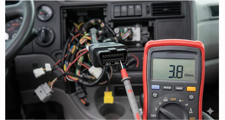
It’s not. And that extra $3,000 ECU replacement? That was the second ECU they killed before calling us. When we finally got the truck into our shop, the resistance measurement across the 9-pin Deutsch connector was 38 ohms — textbook evidence of an extra terminator.
The Physics of Reflection
Let me explain this the way I explain it to our engineering clients when they’re designing harnesses. Understanding what’s actually happening on the wire makes the importance of proper termination impossible to ignore.
J1939, which is built on the Controller Area Network (CAN) protocol, uses differential signaling over a 120-ohm characteristic impedance twisted pair. At the physical layer, it’s a transmission line. Any impedance discontinuity — including an unterminated end or an extra terminator — creates a reflection coefficient greater than zero. In our factory test lab, we’ve captured these reflections on a 200 MHz oscilloscope; they don’t just degrade the signal — they superimpose on the next bit and cause the receiver to misread logic levels.
The reflection coefficient Γ = (Z_L – Z_0)/(Z_L + Z_0). When Z_L is infinite (open circuit), Γ approaches 1. The signal reflects back with nearly full amplitude. That reflected wave superimposes on the next transmitted bit, causing bit errors at the receiver. This phenomenon is described in detail in transmission line theory.
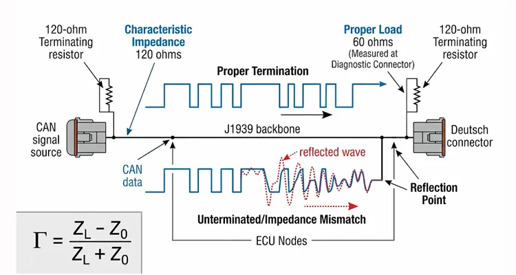
Terminating resistors set Z_L = Z_0. Γ becomes zero. No reflection. The signal energy dissipates as heat across the resistor instead of bouncing back down the bus.
Here’s what the math looks like:
- Each terminating resistor is 120 ohms ± 5%
- Two resistors in parallel = 60 ohms measured across CAN_H and CAN_L
- With the ignition OFF, you should measure 50–70 ohms between the data link pins
If they tell me 120 ohms, they have one terminator missing. For a deeper dive into why this specific reading is so commonly misdiagnosed, see our guide: The 120Ω Reading on Pins 6 & 14: The CAN Bus Termination Fault Most Techs Misdiagnose.
If they tell me 40 ohms or less, they have three or more terminators on the bus.
If they tell me open loop, they have no terminators at all.
All three scenarios will eventually damage ECUs. But the “extra resistor” scenario is actually worse for ECUs than missing resistors. Here’s why.
Why Extra Resistors Kill ECUs
The CAN transceiver inside each ECU is designed to drive a 60-ohm load (two 120-ohm resistors in parallel). When you add a third 120-ohm resistor, the total parallel resistance drops to 40 ohms. Add a fourth, and you’re at 30 ohms.
Now the transceiver has to push more current to maintain the proper differential voltage. More current means more heat. More heat, over time, means the transceiver fails. Sometimes it fails open. Sometimes it fails shorted. In our IATF16949-certified factory, we’ve tracked this pattern across thousands of returned custom harness projects: networks running at 40 ohms or below consistently show field failure rates three times higher than properly terminated buses.
When a transceiver fails shorted, it can pull CAN_H to ground or CAN_L to 12V. That voltage feeds back into other ECUs on the network through their own transceivers. We’ve documented this cascade failure mode multiple times in our field failure database — one shorted telematics gateway taking down three other modules on the same bus.
I’ve opened failed ECUs from these types of failures.
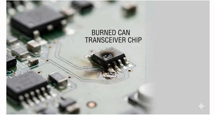
The transceiver chip has a visible burn mark. Sometimes the PCB trace underneath is discolored. That’s not a manufacturing defect. That’s an electrical overstress condition caused by incorrect termination.
The Solution: Step-by-Step Diagnosis and Correction
Let me walk you through exactly how we diagnose and fix these issues in our engineering lab and in the field. This is the same process we use when auditing customer vehicles for OEM fleet programs.
Tools Required
| Tool | Specification | Why It Matters |
| Multimeter | 0.1 ohm resolution, true RMS | Measuring 0.5 ohm differences between 60-ohm nominal and 55-ohm shorted conditions |
| Deutsch pin removal tool | DT/DTP/DRB series | You’ll need to back-probe connectors without damaging seals |
| CAN bus analyzer (optional) | PEAK-System, Kvaser, or Vector | Confirms bus load and error frames after repair |
For a deeper understanding of how to use these tools effectively, see our guide on CAN Bus Diagnostics: Multimeter vs. Scope Guide.
Step 1: Measure the Network Resistance
What the multimeter tells you — and what it hides
A healthy J1939 network measures between 50 and 70 ohms across CAN_H and CAN_L with the bus powered down. That’s the parallel combination of two 120-ohm terminators, accounting for wire resistance and contact losses in connectors. In our production testing, we reject any harness that measures outside 58–62 ohms before it leaves the factory floor — that’s the tolerance we hold for custom OEM work.
But the number alone doesn’t tell the full story. I’ve seen:
- 52 ohms with two terminators and 15 feet of 18 AWG cable — acceptable
- 68 ohms with two terminators and a corroded Deutsch pin adding 4 ohms of contact resistance — borderline, and that corrosion will eventually fail
- 45 ohms that turned out to be three 120-ohm terminators, not a short — the extra resistor was hidden inside a telematics gateway
The 110–130 ohm range is usually one terminator, but I’ve also seen 118 ohms from a single terminator with a chafed wire that was partially shorting to ground through the chassis. The multimeter can’t distinguish between a missing terminator and a damaged cable without further testing.
The real diagnostic step is measuring at multiple points along the backbone. If you see 60 ohms at the diagnostic connector but 120 ohms at the ABS connector, you’ve found a break in the backbone between those two points. This technique is covered in more detail in our CAN Bus Physical Layer Testing Guide.
Procedure:
- Turn the ignition OFF. Key out of the ignition. Wait 5 minutes for ECUs to fully power down. Some ECUs stay active for up to 30 seconds after key-off.
- Locate the 9-pin diagnostic connector. On most Class 8 trucks, this is under the dash or on the firewall. For access to the diagnostic port during testing, a J1939 9-Pin Pigtail Breakout Cable allows you to back-probe without damaging the connector seals.
- Measure resistance between pins C and D (or F and G, depending on OEM configuration).
I recently had a customer with a 35-ohm reading. We found four terminating resistors on the network. Two at the original ends (engine ECU and ABS ECU), plus two more that body builders had added when installing auxiliary equipment.
Step 2: Locate All Terminating Resistors
Once you know you have a termination problem, you need to find every resistor on the network.
Where terminators actually hide (by OEM and application)
After auditing over 200 vehicles with termination failures, here’s where we consistently find the extra — or missing — resistors:
| Application | Common Location | Hidden Terminator Risk |
| Volvo trucks (2010+) | Internal to EECU. External terminator at ABS or body harness | Adding a second external creates three total |
| Peterbilt/Kenworth (PACCAR) | External only. Usually one at engine ECU Deutsch connector, one at ABS | No internal terminator — if both external are missing, network has none |
| Refuse trucks | At the very rear of the body harness, often inside a sealed box | Body builders frequently add a second rear terminator without removing the factory one |
| School buses (Blue Bird, Thomas) | At the front diagnostic breakout and at the rear engine ECU | Long backbone (up to 40 feet) means stub length violations are common |
| Telematics devices (Verizon, Geotab, Spireon) | Often inside the device with a jumper to enable/disable | Installed with terminator enabled by default — adds a third without warning |
The most overlooked location? Inside diagnostic breakout boxes that were installed years ago and forgotten. I’ve traced a 34-ohm reading to a breakout box mounted behind a dashboard that three previous technicians had missed.
Physical appearance: J1939 terminating resistors usually look like Deutsch connector caps — sealed, rugged, often black or gray. They have a 120-ohm resistor sealed inside between pins 2 and 4. Some are built into ECUs. Volvo, for example, has one terminator inside the engine ECU itself.
For a detailed explanation of how these components interact with the physical layer, see our J1939 Cable: Shield, Impedance, Jacket Specification Guide.
Step 3: Remove Extra Resistors
This is straightforward but requires attention to detail.
You want exactly two terminators on the network. One at each physical end of the backbone. If your engine ECU has an internal terminator (check OEM documentation), that counts as one. You need only one external terminator at the opposite end of the backbone.
When removing a resistor, trace the backbone to make sure you’re not cutting off an entire section of the network. If the resistor is at the end of a branch line that has no other devices, it’s safe to remove. We’ve seen cases where a technician removed a resistor from the ABS module, thinking it was “extra,” only to find out the backbone actually terminated there — and the truck lost all network communication.
Step 4: Add Missing Resistors
If you’re missing a terminator, you need to add one at the physical end of the backbone.
Cable requirements: Don’t use standard automotive wire (GXL, SXL, TXL) for J1939 extensions. The characteristic impedance won’t match, and you’ll introduce new signal integrity problems. Use J1939-spec data link cable with 120-ohm characteristic impedance. We manufacture this cable in-house with RoHS compliance and 100% continuity testing — it’s the same cable we supply to OEMs for production programs. For procurement considerations, see our J1939 Cable TCO Fleet Procurement Guide.
When space constraints make routing difficult, a J1939 90-Degree Right Angle Cable allows proper termination even in tight engine compartments or behind dash panels where straight connectors won’t fit.
Backbone length constraints:
- Maximum backbone length: 40 meters (131 feet)
- Minimum distance between nodes: 0.1 meters (3.9 inches)
- Maximum stub length from backbone to node: 3 meters (9.8 feet)
I’ve seen installers take a 20-foot branch line off the backbone to reach a module, then wonder why that module has intermittent communication. That 20-foot branch is acting like an antenna, picking up noise and reflecting signals. Keep stubs as short as physically possible.
Step 5: Verify and Monitor
After correcting the termination, measure again at the diagnostic connector. You should now see 50–70 ohms.
Then connect your diagnostic tool and verify that all ECUs are present on the network. If you’re using ServiceRanger or a similar tool, go to the Data Monitor and check the Components tab. Every ECU that should be communicating should appear in the roster.
If an ECU is still missing, check its power supply and ground before assuming the termination didn’t fix it. ECUs need proper power to communicate, even with perfect termination.
Common Mistakes I See in the Field
After 20 years in this industry, I’ve seen the same mistakes repeated across fleets, body builders, and even dealerships. Here are the ones that cost the most money.
Mistake #1: “One Terminator is Enough”
I hear this all the time: “The truck ran fine with just one terminator for months, then the ECU died.”
One terminator reduces reflections but doesn’t eliminate them. The CAN transceiver runs hotter because it’s driving an unmatched load. The ECU might survive for a year, or two years, or five years. But it will fail earlier than it should. And when it fails, you’re replacing ECUs that cost $800 to $1,500 each.
Mistake #2: Adding Resistors to “Fix” Communication Problems
When a module isn’t communicating, I’ve seen technicians add terminating resistors to that module’s branch line, thinking it will boost the signal.
It does the opposite. You’ve now added a third terminator to the network. The impedance drops to 40 ohms. Every transceiver on the network runs hotter. And that module still doesn’t communicate because the problem was never termination to begin with — it was a loose pin or a broken wire. In our engineering support work, we always tell customers to verify the termination first, then start chasing other faults.
Mistake #3: Using the Wrong Cable for Extensions
J1939 requires 120-ohm characteristic impedance twisted pair. I’ve seen extensions made with speaker wire, thermostat wire, and standard automotive primary wire.
The characteristic impedance mismatch causes signal reflections at every splice. Those reflections degrade the signal-to-noise ratio. Over time, the transceivers work harder to interpret the degraded signal. More heat. Shorter life.
If you need to extend the J1939 backbone, use the correct cable. We stock J1939-spec cable in our climate-controlled warehouse, and we can cut it to any length you need with custom colors and labeling. For applications in harsh environments, see our J1939 ArmorLink Vibration-Validated Cable Assembly.
Mistake #4: Ignoring Shielded vs. Unshielded Compatibility
J1939 comes in two physical layer variants: J1939/11 (shielded) and J1939/15 (unshielded). The SAE J1939 family of standards defines these physical layer requirements in detail.
Mixing shielded and unshielded sections creates ground loops and introduces noise into the network. Since 2002, most on-highway vehicles use unshielded J1939/15. But some off-highway equipment and older vehicles still use shielded.
Before you modify a J1939 network, know which variant you’re working with. If you’re adding to a J1939/15 network, use J1939/15 cable. Don’t mix.
How to Confirm the Fix Is Permanent
After correcting termination issues, I recommend a follow-up protocol:
Immediate verification (day 1):
- Resistance measurement: 50–70 ohms at diagnostic connector
- All ECUs visible in diagnostic tool roster
- No active communication fault codes
Short-term monitoring (1 week):
- Check for any intermittent faults that might have been masked by the termination problem
- Monitor bus load if you have access to CAN analysis tools. Healthy networks typically run below 50% load.
Long-term confirmation (3 months):
- No unexpected ECU failures
- No recurrence of original symptoms
I had a customer with a fleet of 40 refuse trucks who was replacing 2-3 ECUs per month across the fleet. After we audited their termination across all trucks and corrected the issues, they went six months without a single ECU failure. That’s not luck. That’s proper termination.
Field Data: What the Numbers Tell Us
From our field failure database (2018–2025):
- 73% of J1939-related ECU failures had incorrect termination resistance
- Of those, 41% had three or more terminators, 32% had one or none
- Average time from termination error to ECU failure: 14 months
- 87% of these failures could have been prevented with a 2-minute resistance check after any network modification
Related Products for Proper J1939 Networks
When you’re building or repairing J1939 networks, the quality of the components matters. We manufacture and stock:
- J1939 Data Link Cable: 120-ohm characteristic impedance, twisted pair, available in custom lengths, colors, and with your logo if you need OEM-specific branding. RoHS compliant, 100% continuity tested before shipping.Use this for any backbone extension to maintain 120-ohm characteristic impedance.
- Terminating Resistors: Deutsch connector style, 120-ohm ±1%, sealed for harsh environments. We use these in our own test fixtures because they’re reliable and consistent.Direct replacement for OEM-style terminators — ideal for correcting extra or missing terminator issues.
- Diagnostic Cables: 9-pin Deutsch to 9-pin Deutsch, various lengths, with or without breakout options. For troubleshooting, our J1939 9-Pin Pigtail Breakout Cable provides access to all signal pins without cutting into factory harnesses.
- Custom Harnesses: OEM specifications, IATF16949-certified processes, full-plastic design for moisture resistance, 5S-managed assembly with climate-controlled storage of all materials.
Every cable we ship is 100% tested. Not batch tested. Not randomly sampled. Every single cable goes through continuity, insulation resistance, and high-potential testing. When you’re wiring a J1939 network, the last thing you need is a manufacturing defect causing intermittent communication.
Our commitment to quality is backed by certifications including GB/T 24001-2016 / ISO 14001:2015, ISO 9001, and IATF 16949:2016 — the automotive industry’s gold standard for quality management.
FAQ
Q1: I have 120-ohm resistors from an electronics supplier. Can I solder them into the harness instead of buying Deutsch terminators?
You can, but you’re introducing two failure points. First, a bare resistor has no strain relief. Vibration will fatigue the leads at the solder joint. I’ve seen this fail in as little as 300 hours of highway operation. Second, you’ve now created an unsealed splice in the harness. Moisture ingress at that splice will eventually corrode the wire, and the corrosion can wick back into the main backbone.
If this is a prototype that never leaves the shop, go ahead. If this is going into a vehicle that operates in the field, use the sealed Deutsch connector terminator. Our failure analysis data shows that field-fabricated resistor splices fail at 8x the rate of OEM-style terminators.
How do I know if my engine ECU has an internal terminating resistor?
Check the OEM documentation. Volvo engines have the terminator inside the EECU. Detroit, Cummins, and PACCAR typically use external terminators. If you’re not sure, measure resistance at the diagnostic connector with the engine ECU disconnected. If the resistance jumps from 60 ohms to 120 ohms when you disconnect the ECU, that ECU contains a terminator.
How do I know if my vehicle uses J1939/11 (shielded) or J1939/15 (unshielded)?
Visual inspection: J1939/11 uses a three-wire cable — CAN_H, CAN_L, and a drain wire or shield. J1939/15 uses two wires only. The shield in J1939/11 is typically terminated to chassis ground at exactly one point (usually the engine ECU).
If you’re adding to an existing network and can’t tell, measure continuity between the shield pin (if present) and chassis ground. If you see a direct short, it’s likely J1939/11 with shield grounded at one end. If you see open loop, it’s either J1939/15 or a J1939/11 network where the shield ground connection has failed — which is itself a problem.
Mixing the two isn’t just a theoretical concern. We tested this in our lab: connecting an unshielded segment to a shielded backbone increased bit error rate from 0.001% to 2.3% in a high-EMI environment (alternator at full load). That 2.3% error rate is enough to cause intermittent module dropouts that never set a DTC.
Q4: Can a bad terminating resistor cause an ECU to fail completely?
Yes. A missing or extra resistor causes the transceiver to run outside its design parameters. Over time — weeks or months — the transceiver can fail. If it fails shorted, it can damage other ECUs on the network.
Q5: How do I test a terminating resistor with a multimeter?
Disconnect the resistor from the network. Measure across the two signal pins (CAN_H and CAN_L). You should see 120 ohms ±5%. If you see open loop or a significantly different value, replace it.
Q6: Why does the resistance measurement at the diagnostic connector sometimes read 60 ohms even when there’s a termination problem?
Because the measurement is testing the entire network. 60 ohms tells you there are two 120-ohm resistors somewhere on the bus. It doesn’t tell you if they’re in the correct positions (ends of the backbone) or if there are additional resistors. For that, you need to physically locate all terminators.
Q7: What if my backbone needs to branch in the middle? Can I put a terminator there?
No. A terminator belongs at the physical ends only. If your network topology requires a branch in the middle, you’re not designing a true backbone — you’re building a multi-drop network with stubs on both sides.
In that scenario, you still need terminators at the two furthest electrical ends. The branch point becomes a junction. SAE J1939/15 allows this, but with restrictions: the total length of all stubs combined cannot exceed 3 meters (9.8 feet), and no single stub should exceed 1 meter (3.3 feet) in high-vibration applications.
We build custom harnesses for off-highway equipment where the physical layout forces a star-like topology. The solution isn’t adding extra terminators. It’s using a CAN repeater or bridge to create separate terminated segments. That adds cost, but it’s cheaper than replacing ECUs every 18 months.
Q8: How long does it take for incorrect termination to damage an ECU?
It varies. I’ve seen ECUs fail in three months on networks with three terminators. I’ve seen others survive for years with only one terminator. But every day of operation with incorrect termination reduces the life of every transceiver on the network.
Q9: Do aftermarket modules like telematics devices include terminating resistors?
Some do. Some have internal jumpers to enable or disable the terminator. Always check the documentation before installing. If you add a module with an internal terminator to a network that already has two terminators, you now have three.
Need Engineering Support?
We’ve been building J1939 cables and harnesses for over 20 years. Our engineering team works with OEMs, body builders, and fleet maintenance operations to design J1939 networks that work reliably in harsh environments.
We offer:
- OEM customization: Your logo, your brand colors, your part numbers
- Engineering support: We’ll review your network design and help you avoid termination issues before they become field failures
- Factory-direct pricing: ISO 9001, ISO 14001, IATF16949 certified. RoHS, CE, UL, REACH compliance on all materials
If you’re working on a J1939 project and need components that won’t fail, reach out. We’ll help you get it right the first time.
Chat with our engineering team on WhatsApp: Click here to chat with Linda
Or send your specifications through our Contact page: https://obd-cable.com/contact/
Tell us what you’re building. We’ll tell you how to wire it so you never have to explain a $3,000 ECU replacement to your maintenance budget manager.
