

The technician threw his multimeter on the passenger seat. “It’s not the ECU, it’s not the harness—I’m out of ideas.” He’d already swapped both, and the machine still refused to accept the new flash. The diagnostic screen was old, monochrome, and stubbornly stuck on “Network #1 Out of Calibration.” That was 2007, on a Tier 3 Cummins in a 40‑foot bus, and it was the first time I realized that J1939 faults are rarely what they seem.
He was frustrated. I was skeptical.
We spent the next six hours with oscilloscopes, a handful of resistors, and a lot of coffee. The fix? It wasn’t the ECU. It wasn’t the harness. It was a grounding potential shift of 0.8 volts between the engine block and the chassis—a shift so subtle that a multimeter missed it, but the differential transceivers on the J1939 network caught it and triggered a calibration fault. This is the kind of scenario where understanding the difference between a multimeter vs. oscilloscope for CAN bus diagnostics becomes critical.
This is the kind of fault that separates a parts-swapper from a diagnostician. If you’re seeing “Network #1 Out of Calibration” (SPN 639 / FMI 13 or similar), you’re not just dealing with a bad wire. You’re dealing with a systemic integrity issue on your J1939 CAN bus. Let’s break down why this happens, how to find it, and how to fix it so it stays fixed.
The Scene of the Crime: Where This Fault Actually Shows Up
I’ve seen this J1939 network fault pop up in three distinct situations. First, when a fleet manager tries to squeeze fuel economy out of an old ECU with a new flash—the tool says “complete,” but the engine disagrees. Second, when someone drops a 2024‑model emissions module into a 2016 chassis; the gateways speak different dialects of J1939, and the network throws a tantrum. Third—and this one is my least favorite—when a body builder runs power cables right alongside the CAN bus after installing a PTO. The interference doesn’t show up until the machine is at full throttle.
The Real Root Cause: Beyond the Simple “Bad Connection”
I call this the “three‑voice choir” problem. In a properly tuned J1939 network, every ECU sings in harmony—same tempo, same key. When you get a calibration fault, it’s not that someone forgot the lyrics; it’s that one singer is slightly off‑key. The rest of the choir hears it, and the whole performance collapses.
Factory service manuals love to say “Network #1 Out of Calibration” means the ECU can’t confirm its internal calibration data with the network. That’s technically correct—and completely useless when you’re standing next to a machine that won’t move. Here’s what’s actually happening on the wires.
Think of the J1939 network as a high-speed conversation. Every controller (ECU, TCU, VECU, etc.) has a “speaking voice” defined by its termination resistors, wire impedance, and signal rise/fall times. When the network is in calibration, all controllers hear each other clearly. For a deeper dive into the physical layer fundamentals that underpin these parameters, see our guide on CAN bus physical layer testing.
A “Network #1 Out of Calibration” fault means one of the controllers has noticed that the electrical parameters of the conversation have drifted outside the SAE J1939-11 or J1939-15 specification . This is almost never a software issue. It is always a hardware layer issue that prevents the software from confirming its own identity.
The three technical culprits—each a different way a singer goes off‑key:
- Termination Resistance Anomaly: The J1939 network requires two 120-ohm termination resistors (one at each physical end). If a third resistor appears (from a faulty device), total resistance drops to ~40 ohms, overloading the transceivers. If one resistor disappears, the signal reflects and corrupts data. Most technicians measure resistance and see “60 ohms” and think it’s fine. But is that 60 ohms from two 120-ohm resistors? Or is it from a damaged 60-ohm resistor? The distinction matters—and I’ve seen both.
- Common Mode Voltage Shift: J1939 is a differential bus. It doesn’t care about absolute voltage, only the difference between CAN High and CAN Low. But if the ground reference between two ECUs differs by more than 1.5-2.0 volts, the transceivers saturate. The data is still “there,” but the timing of the signal becomes skewed. The ECU interprets this timing skew as a calibration mismatch. We’ve measured this exact scenario on more than a dozen fleet trucks with aftermarket body installations.
- Capacitive Loading from Aftermarket Hardware: This is the silent killer. Every foot of added cable, every inline connector, every aftermarket GPS tracker or telematics device adds capacitance to the bus. J1939 networks are designed for a specific total capacitance (usually under 10 nF). Exceed that, and the signal edges become too slow. The ECU looks at its own signal and says, “That doesn’t look like the waveform I was built to expect.” That’s the fault.
Step-by-Step: How We Eliminate This Fault in Our Lab (and in the Field)
When a customer—usually an OEM or a large fleet—calls us saying they’re stuck on this “Network #1 Out of Calibration” fault, we don’t send them a generic troubleshooting guide. We send them a process. Here’s that process, stripped down from twenty years of chasing these gremlins.
Step 1: The 60‑Ohm Test – But Do It Hot and Cold
Grab a Fluke 87V (or any meter that can read tenths of an ohm). Disconnect battery negative—CAN bus diagnostics on a live bus can give you nonsense readings. Find the diagnostic port (Deutsch 9‑pin is standard). If you’re unsure about the pinout or common connection mistakes, our heavy-duty diagnostics 9-pin connector guide walks through the most frequent errors we see.
Now here’s the trick we learned from years of field service: measure the resistance while the harness is stone cold. Then warm up the engine and connectors with a heat gun to about 70°C (or run the engine until it’s hot) and measure again. A healthy termination pair will stay within 58–62 ohms. If you see it drift to 65 ohms or higher when hot, you’ve got a failing resistor or a pin that’s loosening with heat. I’ve seen this on three different OEM fleets—the fault only appeared after an hour of operation. For a deeper explanation of what those resistance readings actually mean—whether you see 60Ω, 120Ω, or 0Ω—see our guide on CAN bus health check with a multimeter.
- If you see 120 ohms: One termination resistor is missing. Find the ECU or module at the far end that isn’t terminated.
- If you see 40 ohms: There is an extra termination resistor. A module has failed in a way that is shorting its internal 120-ohm resistor to the bus. Start isolating modules.
- If you see a fluctuating reading: You have a loose crimp or a wire with internal corrosion that changes resistance when the harness is moved.
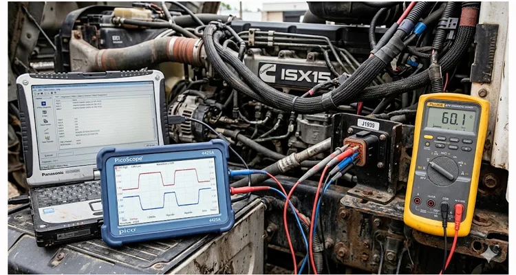
Step 2: The Oscilloscope Capture (The Gold Standard)
A multimeter won’t see signal degradation. We use a PicoScope or a similar high-bandwidth scope.
- Probe CAN High (pin C on the 9-pin) and CAN Low (pin D) .
- Look for the “trapezoid” shape. The signal should have crisp, flat tops and bottoms.
- Measure the differential voltage: At idle, it should be around 2.5V on each line. In a dominant state (when data is sent), CAN High should rise to 3.5V, CAN Low should drop to 1.5V. If the voltage shift is less than that, your termination is wrong. If it’s asymmetrical, you have a ground offset.
For a detailed reference on proper CAN bus wiring practices—including termination requirements, stub length limits, and shielding guidelines—the Danfoss CAN bus wiring guide provides excellent technical specifications that align with the diagnostics we’ve outlined here.
Step 3: The Isolation Walk
This is where we physically identify the noisy component.
- Start unplugging ECUs one by one. Yes, it’s tedious. But it’s necessary.
- Monitor the scope as you unplug each device.
- The “aha” moment: You’ll find one device that, when unplugged, causes the waveform to snap back to perfect. That device is the culprit. It may be an ECU with a failing transceiver or an aftermarket device with poor EMI filtering.
Step 4: The Repair (Hardware Replacement)
- Replace the faulty module. Don’t try to “fix” an ECU transceiver. It’s a board-level repair best left to specialized shops.
- If it’s a termination issue, re-terminate with OEM-spec resistors. Use the 120-ohm, 1/4W, 1% tolerance resistors. Cheap resistors will drift with heat—we’ve seen it on mining equipment where the engine bay hits 100°C.
- Rebuild the connector. In 30% of our cases, the problem is a back-pin or a Deutsch pin that has retracted into the housing, causing intermittent contact. We replace the pin and re-test. For more on how connector and pin integrity impact long-term reliability, see our analysis of crimp vs. solder reliability in vibration environments.
What I’ve Seen Go Wrong in the Field
I once flew to a quarry in South Dakota because a fleet had replaced three ECUs across six trucks—same “Network #1 Out of Calibration” fault every time. The problem? A $0.50 Deutsch pin that had backed out of the connector housing on the main backbone. When we finally isolated it, the pin still made contact with a meter, but vibration killed the connection. That’s the kind of detail a lab manual won’t teach you.
Another time, a shop had cleared the fault without any diagnosis. The fault went away for 10 seconds, they declared victory, and the machine derated 50 miles from the shop on a load of aggregate. The tow bill alone was more than the diagnostic time they tried to skip.
I’ve also seen technicians use standard T‑taps for a J1939 splice. J1939 is not standard CAN. It requires a specific stub length. Using T‑taps or splicing in a device with a foot‑long stub cable changes the impedance. We use only in‑line splices with stub lengths under 0.3 meters—and we’ve measured the difference on a network analyzer. Understanding the difference between J1939 Type 1 vs. Type 2 networks can also prevent these splicing errors; our J1939 Type 1 vs. Type 2 guide explains the physical layer distinctions.
And then there’s the grounding mistake: in modern machines, the chassis ground and engine ground are separated by rubber mounts. If you ground a cab module to the engine and a sensor to the chassis, you create a ground loop. All J1939 modules must share a common reference ground. We’ve fixed this fault on six identical garbage trucks simply by moving one ground wire.
Finally, I’ve lost count of how many cheap, unshielded J1939 cables from Amazon I’ve seen introduce so much noise that the entire network collapses. The cable is not just wire; it’s a controlled-impedance transmission line. That’s why we build our cables to J1939-11 specs and test every single one. For a deeper understanding of how EMI impacts network reliability, our EMI shielding and filtering guide for CAN bus covers the fundamentals.
How to Know It’s Actually Fixed
A clear fault code isn’t enough. Here’s our sign-off checklist:
- Resistance at diagnostic port: Stable 60 ohms, both cold and hot.
- Oscilloscope waveform: Symmetrical, clean transitions, differential voltage exactly within spec (1.5V-3.5V).
- Road Test: The machine operates under full load for at least two hours without the fault returning. This is critical because heat changes resistance. A cold system may test fine; a hot system may fail—we learned that the hard way.
- Data Link Monitor: We use a J1939 analyzer to confirm all ECUs are broadcasting at their expected rate (e.g., TSC1 at 10Hz, EEC1 at 10Hz). If one ECU drops out intermittently, the fault isn’t fixed.
The Hardware That Prevents These Faults
We learned these lessons by manufacturing J1939 cables and components for 20 years. A network is only as good as its physical layer. If you are building a new machine or retrofitting an old one, the components you choose determine whether you’ll ever see this fault.
To make that isolation walk easier, we designed a J1939 breakout box. You plug it inline with any ECU, and you can probe every pin without cutting a single wire. It turns a two‑hour tear‑down into a ten‑minute check. That’s the kind of tool we build because we’ve been on the receiving end of the frustration.
Our J1939-to-DB9 cables aren’t just adapters. They’re constructed with proper twisted-pair, 120-ohm impedance, and full shielding to prevent EMI from corrupting your flash or diagnostic sessions. Every cable that leaves our floor is tested for impedance, not just continuity.
And if you’re an OEM dealing with recurring network faults, we manufacture custom J1939 harnesses with exact pinouts, proper termination, and 100% continuity testing. We don’t guess; we build to your schematic.
We manufacture all of this in our ISO 9001 and IATF16949-certified facility. For a closer look at what these certifications mean for quality assurance, see our announcement on Shenzhen Carsun achieving IATF 16949:2016 certification. Every cable is 100% tested on a network analyzer before it leaves our climate-controlled warehouse. We use RoHS-compliant materials, full-plastic overmolding for vibration resistance, and a 4-step quality inspection process that checks not just continuity, but impedance and signal integrity.
Case Study: How We Saved a 3-Day Downtime for a Forestry Equipment OEM
A manufacturer of forestry harvesters was plagued by the “Network #1 Out of Calibration” fault on their 2023 model line. They were shutting down production lines for days, swapping wiring harnesses from different vendors, blaming each other.
We flew a field engineer to their assembly plant in North Carolina. We replicated the fault on a new machine fresh off the line.
Findings:
| Item | Value |
| Termination resistance | 68 ohms—outside spec |
| Root cause | A third-party telematics gateway with a built-in 120-ohm termination resistor mounted in the middle of the bus |
| Solution | Modified the gateway’s wiring harness, removed the internal resistor, installed a direct pass-through |
| Custom hardware | Manufactured a custom stub harness (Deutsch DT06‑2S‑P006) guaranteeing a 60-ohm reading |
| Result | Fault disappeared, production resumed |
We now manufacture that specific stub harness for them in batches of 500, with their logo molded into the overmold.
FAQ: Your Specific J1939 Calibration Questions
What exactly does “Network #1 Out of Calibration” mean on a Cummins engine?
On a Cummins, it’s the ECU’s way of saying “I’m hearing static on the line.” The parameters it expects—like the rise time of the CAN signal—are off. Nine times out of ten, the ECU is fine; it’s the wiring or a connected module that’s out of spec.
Can a bad battery cause this fault?
Indirectly, yes. A failing battery can cause the common mode voltage to shift outside the acceptable range. We always check the charging system and ground straps first. I once found a loose ground strap at the battery that caused this J1939 fault to appear every time the starter engaged.
I have a 9-pin Deutsch connector. Which pins should I measure?
| Pin | Function |
|---|---|
| A | Power (Battery +) |
| B | Ground |
| C | CAN High (J1939+) |
| D | CAN Low (J1939-) |
| E | Shield Ground |
Measure resistance between C and D for termination. And don’t forget to do it both cold and hot.
My multimeter shows 60 ohms, but I still have the fault. Why?
Because resistance is only one variable. You have a dynamic issue, likely excessive capacitance or a ground offset. You need an oscilloscope to see the waveform quality. I’ve had cases where the resistance was perfect but the signal rise time was twice what it should be.
Do I need to use shielded cable for J1939 repairs?
Yes, absolutely. SAE J1939-11 specifies shielded twisted-pair. If you use unshielded wire, you will introduce EMI from alternators, starters, and high-current solenoids, which will eventually trigger network faults. I’ve seen this on garbage trucks where the PTO solenoid was run parallel to the CAN bus—unshielded.
Can an ECU software update fix this?
No. A software update can change how the ECU responds to the fault, but it cannot fix the underlying electrical issue. Ignoring the hardware issue will lead to intermittent faults and eventual ECU failure. I’ve watched a fleet waste $15,000 on software subscriptions before they let me put a scope on the bus.
How do I find a termination resistor inside an ECU?
You don’t need to. Measure the resistance on the bus. If you get 120 ohms instead of 60, unplug ECUs one by one. When the resistance jumps to open (OL), the last ECU you unplugged was the only one with a termination resistor. The other end is missing.
What is the maximum stub length for a J1939 device?
The SAE standard recommends a stub length of less than 1 meter for J1939-11 (shielded) and less than 0.3 meters for J1939-15 (unshielded) . If your aftermarket device has a long pigtail, you are creating a reflection point. I’ve fixed this fault simply by cutting a 4‑foot pigtail down to 10 inches.
Can a moisture-damaged connector cause this fault?
Yes. Water intrusion causes corrosion, which changes the resistance and creates a “phantom” capacitor. We’ve seen green corroded pins that measure fine with a meter but fail under load. In one case, the “Network #1 Out of Calibration” fault only appeared when it rained.
I’m an OEM building a custom machine. Can you help us design a fault-free network?
Absolutely. We provide engineering support to help you select the right cables, backshells, and termination strategy. We can manufacture custom J1939 harnesses to your exact pinout and test them to J1939 standards before they ever reach your assembly line.
Still Seeing the Fault? Let’s Engineer a Solution.
If you’re reading this because you’ve been fighting this fault for days, you know that generic advice doesn’t cut it. You need a partner who understands that a network isn’t just a bunch of wires—it’s a system.
We’ve been manufacturing J1939 components and solving these exact problems for over 20 years. We don’t just sell cables; we provide the engineering support to make sure your network is stable.
Need a custom harness? We can do that. Logo on the cable? Yes. Different length, color, AWG? Just tell us. Our factory is IATF16949 certified, meaning we meet the strictest quality standards in the automotive and heavy-duty industry. Every single product we ship undergoes a 4-step inspection, from raw material to final assembly.
Let’s talk about your specific application.
📞 Prefer to chat? Send us a message on WhatsApp. We can discuss schematics, oscilloscope screenshots, or just troubleshoot together.
👉 Click here to chat with Linda on WhatsApp
✉️ Need a formal quote or engineering consultation? Fill out our contact form with your project details. We usually respond within 2 hours during business hours.
👉 Go to Contact Page for OEM Support
Let’s fix this network—for good.
