

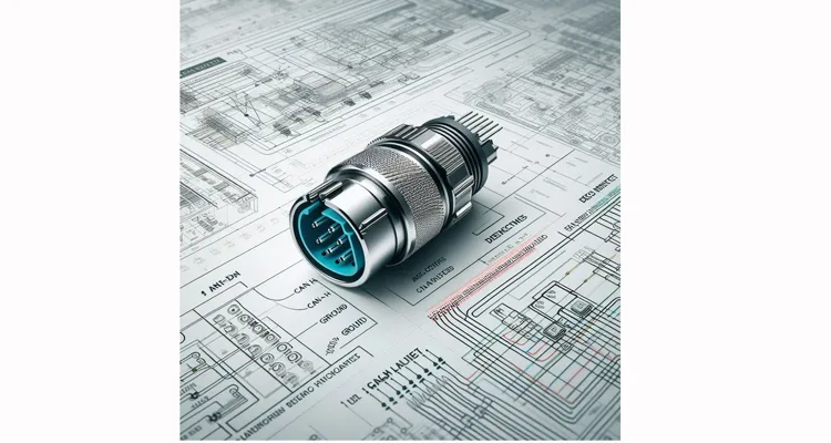
You’re staring at a heavy-duty 9-pin Deutsch DT connector in your hand. The diagnostic tool is on, the software is ready, but the screen relentlessly shows “NO COMMUNICATION.” You’ve verified the obvious, yet the issue remains. Often, the solution—or the decisive next step—is found not in the software, but in the electrical roadmap defined by the J1939 connector pinout.
Basic pinout tables are easy to find online, but they are often lifeless lists that fail to bridge the gap between a diagram and actionable diagnosis. This guide is different. We dissect what each signal actually does in a live system, why its integrity is non-negotiable, and how its failure truly behaves on the shop floor. This is the manual we compiled from two decades of field and bench work, diagnosing issues that a perfect schematic could never reveal.
Why a Deep Dive Into the J1939 Pinout Is Your First Real Diagnostic Step
For a fleet manager, a communication fault is lost revenue. For an integration engineer, a single miswired pin can derail a project timeline. The common error is treating the J1939 connector pin diagram as a simple connectivity check. This underestimates its role.
The SAE J1939 standard is the dictionary—it defines the words. The physical layer—the wires, pins, and shielding—is the voice that delivers them. A perfect message sent through a degraded medium becomes noise. Therefore, understanding the pinout is about comprehending the electrical purpose of each circuit. This foundational knowledge enables you to:
- Diagnose with Precision: Shift from swapping parts to executing targeted tests. Is the root cause on the CAN bus differential pair, or is it a corrupted power reference?
- Specify with Confidence: Procure or fabricate cables that match your vehicle’s exact configuration, avoiding costly “universal” parts that fit nothing well.
- Solve Intermittents: Decipher how a single corroded ground pin (Pin 1) can cause cascading, seemingly random failures across multiple vehicle systems, a pattern we detailed in our guide to systematic intermittent OBD-II communication faults.
The Standard J1939-13 9-Pin DT Connector Pinout: An Annotated Systems Blueprint
| Pin | Signal Name | Description & Core Function | Critical Engineering Notes & Observed Failure Symptoms |
| 1 | Battery Ground | The primary 0V reference and current return path to chassis/battery negative. | The system’s anchor point. A voltage drop exceeding 0.1V under load here skews the reference for every ECU. Field Evidence: We’ve documented instrument clusters resetting during cranking and phantom ABS codes—issues often misdiagnosed as module failures. A low-impedance ground connection is the first rule of robust vehicle electronics. |
| 2 | J1939 CAN Bus Low (CAN_L) | The complementary low-voltage line of the CAN bus differential pair. | With Pin 3 (CAN_H), carries the network data. Idle voltage is ~2.5V. Diagnostic Insight: While a hard short kills communication, subtler induced noise from improper shield (Pin 5) handling is a frequent culprit behind elusive, sporadic data errors. |
| 3 | J1939 CAN Bus High (CAN_H) | The complementary high-voltage line of the CAN bus differential pair. | Idle voltage is ~2.5V. Measurement Intelligence: The ~60-ohm resistance measured across Pins 2 & 3 (key off) confirms network terminators. On newer Volvo/Mack architectures, we measure ~115 ohms due to a single integrated terminator—adding an external one here will cause failure. |
| 4 | Battery Positive (+) | Unswitched, direct connection to battery positive for keep-alive memory. | Powers ECUs that must retain adaptation data and fault history (e.g., engine ECM). Failure Mode: A break here may allow the engine to run but causes a total loss of learned parameters and DTC history at key-off. Commonly mistaken for Pin 8. |
| 5 | SAE J1939 Shield | The drain wire for the overall foil or braid shield. Not a current carrier. | The EMI Gatekeeper. Our field rule: terminate to chassis ground at one end only (typically the diagnostic port). A shield grounded at both ends forms a “ground loop antenna.” Documented Case: A refuse truck exhibited corrupted RPM data only during compactor operation, perfectly simulating a faulty sensor. The shielded vs unshielded J1939 cable TCO analysis quantifies the cost of this error. |
| 6 | SAE J1708/J1587 Data+ (Optional) | Positive data line for the legacy J1708/J1587 serial network. | Found on older vehicles for basic trip data. Integration Note: It can coexist on a vehicle with J1939. Failures are typically straightforward opens or shorts on this less robust, single-wire bus. |
| 7 | SAE J1708/J1587 Data- (Optional) | Signal return for the J1708 network. | Used with Pin 6. In some implementations, this pin is internally tied to ground and may not be present. |
| 8 | Switched Battery Positive (Key-On) | Ignition-switched power for waking ECUs and diagnostic tools. | The Primary Suspect: This is the #1 pin to verify when your scan tool has power but shows “NO COMM.” A missing voltage here means ECUs are asleep. Our dedicated guide on the OBD2 port not communicating hardware diagnostic protocol provides a full checklist. |
| 9 | Battery Positive (+) – Higher Current | A second, dedicated battery feed, often for high-demand accessories. | Typically fused separately from Pin 4. Design Warning: Using this circuit for aftermarket devices without verifying its fuse rating and load capacity is a documented fire risk in upfit scenarios. |
Beyond the Standard: Navigating OEM-Specific Pin Assignments
Here, the published standard intersects with engineering reality. OEMs frequently repurpose undefined pins (like 6 & 7 if J1708 is absent) for proprietary functions.
- Cummins INSITE™: May use a dedicated pin for a proprietary diagnostic line parallel to the standard CAN bus.
- John Deere: Agricultural implements often employ extra pins for proprietary implement bus communications or high-current solenoid control.
- PACCAR (Kenworth, Peterbilt): Variations exist for body builder interfaces, sleep-mode signals, or custom data links.
The Unbreakable Rule: Never Assume. For OEM customization or critical integrations, the vehicle-specific wiring diagram is law. Guessing leads to non-functional systems. Our process for building zero-defect custom cable assemblies is governed by IATF 16949 and begins with this exact verification, supported by a formal IATF 16949 pre-production checkup.
A Field Engineer’s Guide: Using the Pinout for Real Diagnostics
This is our systematic, battle-tested approach to translating pin definitions into fault isolation.
Step 1: Verify Power and Ground Integrity (Pins 1, 4, 8, 9).
- Measure voltage between Pin 1 (Ground) and Pin 4 (B+). Expect system voltage (~12-24V).
- Measure between Pin 1 and Pin 8 (Key-On). Expect system voltage only with ignition on.
- Assess Pin 1 Quality: Perform a voltage drop test under load (e.g., headlights on). More than 0.1V between Pin 1 and a pristine chassis point indicates a problematic ground.
Step 2: Interrogate the CAN Network (Pins 2 & 3).
- Measure DC voltage from Pin 2 to ground (~2.5V).
- Measure DC voltage from Pin 3 to ground (~2.5V).
- Expert Context: A reading like 2.1V may indicate a voltage drop across a long, undersized backbone cable, not a faulty ECU transceiver.
- Measure DC voltage between Pins 3 and 2. Should be near 0V at idle.
- The Definitive Check: With the key OFF and connector disconnected, measure resistance between Pins 2 and 3. Expect ~60 ohms (or sometimes ~115 ohms as noted). An open circuit (OL) suggests missing terminators.
Step 3: Validate the Shield (Pin 5).
Visually and electrically confirm it has a single-point chassis ground connection and is not used as a signal wire.
Common J1939 Pinout and Wiring Errors: A Diagnostic Deconstruction
Understanding the J1939 Pin Diagram for Effective Diagnostics
These mistakes persist because their symptoms are deceptive.
Error 1: Neglecting Pin 1 (Ground) as a Mere “Wire.”
- The Failure Chain: Inadequate gauge/poor contact → High resistance → All ECU reference voltages shift.
- The Costly Misdiagnosis: Technicians replace sensors or flash ECUs for “intermittent faults,” unaware the root cause is a bad ground, as explored in our guide on systematic intermittent OBD-II communication faults. This is why our 5-step quality inspection mandates ground circuit validation.
Error 2: Inverting CAN_H and CAN_L.
- The Failure Chain: Reversed polarity on the differential pair → No valid signal.
- The Reality: The network is dead on arrival. This is a fundamental assembly error our processes are designed to prevent, and a key risk with poorly designed OBD2 splitter cables.
Error 3: Misapplying the Shield (Pin 5) Termination.
- The Failure Chain: Double-ended grounding creates a ground loop; a floating shield is inert.
- The Elusive Symptom: Not broad-spectrum noise, but context-specific data corruption (e.g., only when a PTO engages) that perfectly mimics a failing component. Our shielded vs unshielded J1939 cable TCO analysis explains the engineering behind proper shielding.
Error 4: Confusing J1939 with OBD-II (Pin 16) Logic.
- The Failure Chain: Applying light-duty vehicle pinout knowledge to a heavy-duty J1939 system.
- The Error: The physical and electrical standards differ. For light-duty issues, refer to our dedicated OBD2 hardware diagnostic guide.
Error 5: Assuming “Standard” Covers Proprietary Pins.
- The Failure Chain: Plugging a generic cable into a system with OEM-specific pin functions.
- The Result: A dead interface. Always obtain the manufacturer’s diagram for your specific model year.
The True Measure of Success: Validating a Robust J1939 Connection
Reliability is defined by performance under stress, not just a passing bench test.
- Communication Stability: Monitor live data and error frames over an extended period, especially during engine cranking and accessory cycling. No drops or corrupted PIDs.
- Environmental Endurance: The link must survive its operational hell. For agricultural machinery, this means resisting mud, chemicals, and constant vibration.
- Long-Term Integrity: No degradation from thermal cycling, flexing, or corrosion. This demands high-quality materials, validated crimp terminations (superior to solder in vibration), and sealed connectors. Our focus on RoHS-compliant, full-plastic design and rigorous testing, as described in OBD-II cable failure points: bridging test to field, targets failures like those analyzed in the 3cm fracture zone OBD2 cable failure.
Engineered Solutions: From Standard Cables to Custom Harnesses
Understanding the pinout reveals why commodity cables fail. Our product philosophy is built on this distinction.
- Standard & Heavy-Duty J1939 Cables: Manufactured with correct gauge wire, proper shielding, and authentic Deutsch connectors. Explore our truck cable and diesel car cable ranges.
- OEM & Custom Harnesses: The solution when your application involves proprietary pins, extreme lengths, or harsh environments (e.g., cold storage). This is our specialty.
- Diagnostic Adapters & Splitters: Critical for interfacing. Selecting designs that prevent bus conflicts is essential, a topic detailed in our analysis of OBD2 splitter problems.
J1939 Connector Pinout FAQ
Q1: Is the J1939 9-pin connector the same as OBD-II?
A: No. They are distinct physical and electrical standards. J1939 serves heavy-duty vehicles (trucks, agriculture). OBD-II is for light-duty passenger vehicles. Some equipment may have both ports.
Q2: My diagnostic tool powers up but gets “NO COMMUNICATION.” Which pins should I check first?
A: Follow this priority: 1) Confirm Pin 8 (Switched B+) has power with the key on. 2) Verify the CAN bus pair (Pins 2 & 3) show ~2.5V each to ground. 3) Never assume Pin 1 (Ground) is good—test its quality under load. Our full protocol is in the guide OBD2 port not communicating.
Q3: Why does my vehicle show ~115 ohms between CAN_H and CAN_L, not 60 ohms?
A: This is correct for many modern systems. ECUs in brands like Volvo, Mack, and some PACCAR models have an integrated 120-ohm terminating resistor. One internal resistor yields a parallel measurement of ~115 ohms. Installing an additional terminator will overload the network.
Q4: Can I make my own J1939 cable?
A: For a basic test lead, possibly. For a reliable field cable, it’s challenging. Achieving consistent shield termination, strain relief, and connector sealing for harsh environments requires specialized tooling and process control. For fleet or OEM integration, a professionally built cable mitigates risk, a concept explored in our reliability premium cost breakdown. Vetting a supplier is crucial; use our J1939 supplier audit framework.
Q5: My vehicle has a 6-pin or 12-pin connector. Is this still J1939?
A: Possibly. The J1939-13 standard includes 6-pin and 12-pin variants for different applications. The pin functions change. Always consult the manufacturer’s documentation.
Q6: What’s the difference between “battery positive” on Pin 4 and “switched battery positive” on Pin 8?
A: Pin 4 is “always hot,” providing constant memory power. Pin 8 is “switched,” activating only with the ignition to wake modules and power tools. This allows for system sleep modes.
Q7: How do I know if I need a shielded J1939 cable?
A: If your environment has high electromagnetic interference (EMI) from sources like VFDs, welders, or large motors, or if the cable run is long, a properly shielded cable is mandatory. The shield (Pin 5) is the defense.
Q8: We are an equipment manufacturer. Can you make custom J1939 harnesses with our logo and specific lengths?
A: Absolutely. OEM customization—encompassing logo, branding, length, color, AWG, and unique pin mapping—is central to our service. It starts with an engineering review of your requirements, backed by our IATF 16949:2016, ISO 9001, and ISO 14001 certified quality system
Q9: What quality certifications back up your cable assemblies?
A: Our manufacturing is certified to IATF 16949:2016, the automotive quality management standard. We also maintain ISO 9001 for quality and ISO 14001 for environmental management. Components meet RoHS, REACH, CE, and often UL standards. Every custom project includes PPAP (Production Part Approval Process) documentation.
Q10: What’s the first step to getting a custom J1939 cable or harness?
A: Contact us with your vehicle/equipment model, application details, and any schematics. Our engineering team will provide a free, no-obligation pinout review and signal integrity assessment.
Internal Links & Engineering Support
A correct pinout is the first link in the reliability chain. What follows is robust execution.
- To understand how we predict and prevent specific failure points, read our analysis of the 3cm fracture zone in OBD2 cable failure.
- For a disciplined approach to vendor selection, see our J1939 supplier audit checklist.
- The business case for this rigor is made in our cornerstone article: The Real Cost of the Reliability Premium.
Contact & CTA
This guide synthesizes twenty years of diagnosing communication failures from the cab to the test bench. If your challenge involves J1939 connectivity—whether you’re battling a persistent “NO COMM” fault, integrating a new subsystem, or sourcing OEM custom harnesses built to exact specifications—let’s connect on an engineering level.
We provide a free, no-obligation pinout and application review. Submit your schematic or requirements, and our team will offer technical feedback and guidance on the optimal cable solution.
Ready to solve your specific J1939 pinout and cabling challenge?
- Chat directly with our engineering support team on WhatsApp.
- Or, submit a detailed inquiry via our Contact Page for a comprehensive follow-up.
External Authority Links:
- SAE International – Overview of the J1939 standards family.
- CAN Bus – Wikipedia entry explaining the Controller Area Network protocol.
