

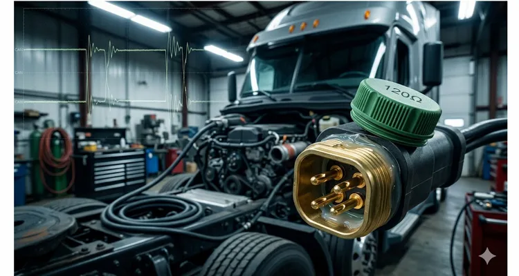
A few winters ago, I stood next to a 2021 Class 8 tractor in a service bay just outside Indianapolis. The truck had been towed in three times in six weeks. Three different shops. Three different theories. The symptom was always the same: the dash would light up like a Christmas tree, the transmission would drop into limp mode around 45 mph, and the scan tool would show a cascade of J1939 communication faults—SPN 639 FMI 9, lost communication with the engine ECU, intermittent ABS messages. The third shop had replaced the engine ECU. That didn’t fix it. The fourth shop—the one that finally called me—found the problem in eleven minutes. The culprit? A single 120-ohm terminating resistor. Someone had added a third one, tucked behind the cab, when installing an aftermarket telematics gateway. The bus impedance measured 40 ohms instead of 60. The network was essentially shouting at itself.
I’ve been building and troubleshooting heavy-duty diagnostic harness assemblies since 2005, and I can count on one hand the number of J1939 failures I’ve seen that were genuinely caused by a failed ECU. Almost every single time, the problem lives in the physical layer—the copper, the connectors, the backbone physical layout. And almost every single time, the root cause traces back to a handful of decisions someone made when the harness was designed or modified. Get these decisions right the first time, and your in-vehicle network will run for a decade without a hiccup. Get them wrong, and you’ll chase ghosts until the fleet manager stops taking your calls.
Let’s walk through the decisions that actually matter. I’m not going to recite the spec at you—you can download SAE J1939/11 and J1939/15 yourself if you want the formal language. What I’m going to share is what twenty-plus years of field debugging across construction sites, mining pits, and fleet yards has taught me about where the spec’s numbers come from, why they’re conservative in some places and dangerously optimistic in others, and how to make your J1939 backbone survive the real world. If you need a broader introduction to the vehicle bus standard that defines this entire ecosystem, Wikipedia has a solid overview of how J1939 fits into the heavy-duty communication landscape.
The physics you can’t negotiate with
If you put a scope probe on pins C and D of a 9-pin Deutsch diagnostic connector, you see the two signals dancing opposite each other. That’s the differential signaling doing its job—rejecting the electrical screaming from the alternator and the solenoids that would otherwise corrupt CAN bus communication. But the part that bites you in the field isn’t the steady-state voltage. It’s what happens when an edge hits the end of the line.
The physics is unforgiving. A 5-nanosecond edge hits the open end of a wire and bounces back like it just hit the jake brake. At 250k, that echo lands right in the middle of the next bit’s decision window, distorting the voltage level enough that a recessive bit gets misread as dominant, or vice versa. That’s why termination exists: the 120-ohm resistor across CAN_H and CAN_L matches the characteristic impedance of the twisted-pair cable, absorbing the energy that would otherwise reflect. With both end-terminators in place, the DC resistance between CAN_H and CAN_L should measure 60 ohms when the network is powered down. For a deeper dive into the voltage parameters, refer to our guide on J1939 CAN High and CAN Low normal voltage ranges.
I learned this lesson the hard way years ago, before I fully grasped the transmission line theory side of things. A fleet of delivery trucks kept dropping random nodes offline—no pattern, no consistency. We swapped ECUs, reflashed firmware, replaced the entire dash cluster on one truck. Nothing worked. Finally, an old-timer on the team asked me one question: “Did you measure the bus resistance with everything unplugged?” I hadn’t. When I did, I found 120 ohms at the diagnostic connector. One of the termination resistors—the one buried inside the engine harness—had a cracked solder joint where the resistor met the connector pin. It was mechanically connected but electrically open. The bus was only terminated at one end, reflections were corrupting about one in every thousand frames, and the ECUs were timing out waiting for messages that never arrived intact. The fix took thirty minutes and cost about eight dollars in parts.
The J1939 specification gives us hard numbers: backbone maximum 40 meters, stub maximum 1 meter (or 3 meters under J1939/15), exactly two 120-ohm terminators at the physical ends of the backbone, maximum 30 nodes. But here’s what the spec doesn’t tell you: these numbers assume ideal conditions. They assume your shielded twisted pair has consistent impedance along its entire length. They assume your stubs are perfectly perpendicular to the backbone with no dangling unterminated ends. They assume your ground reference is clean and your shield is properly bonded at exactly one point. In a real truck or piece of yellow iron, none of these assumptions hold perfectly. That’s why I treat the spec as a starting point, not a guarantee.
The three decisions that determine whether your network works—or haunts you
Stub length: 1 meter isn’t a suggestion, and here’s why
If I could fix one mistake across every J1939 installation I’ve ever seen, it would be this: people treat stub length as a suggestion rather than a hard physical constraint. I’ve walked onto mining sites and seen stubs that snake three meters across a cab, zip-tied to a harness that loops around for “serviceability.” I’ve seen diagnostic connectors on six-foot pigtails dangling under dashboards. Every single one of those installations had intermittent J1939 impedance mismatch symptoms that the OEM couldn’t reproduce on their bench.
Here’s the physics behind the 1-meter limit. At 250 kbit/s, the signal rise time is on the order of a few hundred nanoseconds. A stub acts as an unterminated transmission line stub—it’s a dead-end branch off the main J1939 backbone. When a signal edge travels down the backbone and encounters the junction where a stub connects, part of the energy goes down the stub, hits the end (the ECU’s transceiver input, which is high-impedance), and reflects back. The longer the stub, the later that reflection returns. If it returns during the bit sampling window, you get bit errors. J1939/11 sets the limit at 1 meter because that keeps the reflection delay safely below the critical threshold for 250 kbit/s signaling. J1939/15, which is the “light” variant using unshielded twisted pair and only 10 nodes, allows 3 meters—but that’s because it assumes different transceiver characteristics and lower overall bus loading. I personally don’t go above 0.5 meters if I can avoid it, and I’ve never regretted being conservative on this number.
A couple of years ago, I worked with a customer integrating a third-party telematics unit into a mixed fleet of vocational trucks. The installation instructions said “connect to J1939 backbone”—no further guidance. The installer found a convenient 3-pin Deutsch DT connector near the fuse panel, built a 2.5-meter cable to reach the telematics unit mounted behind the seat, and called it done. The truck ran fine for about three weeks, then started throwing random ABS faults. The telematics unit was on a stub nearly three times the spec limit, and the reflection pattern was right on the edge of causing bit errors. Some days it worked; some days it didn’t. The fix was simple: we relocated the telematics unit closer to the backbone connection point and built a proper stub under 0.3 meters. The ABS faults never came back.
What actually works in the field: Measure your stub from the splice point on the backbone to the ECU connector pin. Not the length of the cable assembly—the actual electrical path. If you’re using a Deutsch DT connector with a molded Y-splitter, the stub length includes the length of that splitter’s branch. And for diagnostic connectors, mount them directly on the backbone with minimal stub—don’t put them on a 1-meter pigtail “for convenience.” That convenience will cost you hours of diagnostic time later. I’ve documented a real-world case where a single 4.2‑meter stub cost a fleet over $4,000 in misdiagnosis—you can read the full J1939 termination and stub length phantom fault analysis for the exact numbers.
Termination: exactly two, exactly 120 ohms, exactly at the ends
Let me tell you about the most expensive service call I ever made. A large construction fleet had three identical excavators. Two ran perfectly. The third would randomly throw J1939 communication faults—sometimes once a week, sometimes three times a day. The dealer had replaced the engine ECU, the display, the entire main harness, and the transmission controller. Nothing fixed it. They flew me out for a site visit.
I measured the bus resistance at the diagnostic connector: 60 ohms. Perfect. I measured it again with the ignition on: still 60 ohms. Then I unplugged the engine ECU and measured again: 60 ohms. Wait—if the engine ECU was unplugged, and it contained one of the two termination resistors, the resistance should have jumped to 120 ohms. It didn’t. That meant there was a third termination resistor somewhere in the harness. After tracing the backbone, we found a small Deutsch termination cap tucked behind a panel near the cab—a leftover from a prototype telematics installation that someone had forgotten to remove. The bus had three 120-ohm resistors in parallel, producing 40 ohms of termination. The CAN transceivers couldn’t drive the bus to the full differential voltage reliably, and communication failed intermittently depending on temperature and battery voltage. Removing the extra terminator fixed the machine permanently. The total cost of that service call—flights, hotels, labor, and the three previous failed repairs—probably exceeded twenty thousand dollars. The fix was free.
The J1939 specification requires exactly two 120-ohm termination resistors—one at each physical end of the backbone. The resistance between CAN_H and CAN_L with the network powered down should measure 60 ohms (two 120-ohm resistors in parallel). If you measure 120 ohms, one terminator is missing or open. If you measure 40 ohms, you have three terminators. If you measure something else entirely, you have a wiring fault.
One nuance that catches people: some ECUs—particularly engine controllers and transmission controllers—have built-in termination resistors. Allison’s 5th Generation Controls TCMs include an internal 120-ohm terminator, for instance. If your backbone physically ends at the engine ECU and at the transmission ECU, and both have internal termination, you don’t need external termination caps. But if you’re designing a harness where the backbone extends beyond those ECUs—say, to a diagnostic connector or a telematics gateway—you need to understand which nodes are providing termination and which aren’t. I’ve seen harnesses where the engine ECU provided one terminator, an external cap provided the second, and a third-party display with an internal terminator (set by a DIP switch someone forgot to disable) added a third. That’s how you get 40 ohms and a truck that won’t shift out of first gear.
The practical approach: Before connecting anything to an existing backbone, measure the resistance between CAN_H and CAN_L. If you see 60 ohms, the bus is properly terminated and you should not add any additional termination. If you see 120 ohms, the bus has only one terminator—you’ll need to add a second if you’re extending the backbone. Never, ever add termination without measuring first. This takes thirty seconds and a ten-dollar multimeter. It will save you days of troubleshooting. For a visual reference, you can check our J1939 wiring diagram for CAN High and CAN Low.
Backbone topology: it’s a straight line, not a tree
I once visited a customer who had built a custom harness for a fleet of specialty service vehicles. They’d designed what they thought was a clever network topology: a central junction box with the display unit, and four separate branches running to the engine bay, the transmission, the ABS module, and the telematics gateway. They’d terminated each branch with a 120-ohm resistor—six resistors total. Nothing worked. The bus was essentially a star topology with multiple unterminated stubs and multiple termination points. The waveforms on the oscilloscope looked like abstract art.
Picture a long, straight rail with short spurs for coal cars. That’s a working J1939 backbone. Picture a wagon wheel with spokes meeting at the hub. That’s the oscilloscope from my visit to that custom fleet job—abstract art and zero communication.
The illustration below contrasts a proper J1939 linear bus topology with the problematic star topology that causes signal reflections and communication failures.
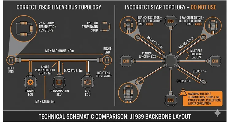
J1939 requires a linear bus topology—a single backbone with exactly two ends. Every ECU connects to this backbone via a stub. You cannot branch the backbone itself. You cannot have a “T” junction where three backbone segments meet. You cannot daisy-chain ECUs by connecting one ECU to the next in series unless the cable between them is part of the backbone and the stubs to each ECU branch off that backbone—which requires very careful design.
In practice, many harnesses implement this by having a dedicated backbone cable that runs the length of the vehicle, with splice points where stubs break out to individual ECUs. The splices must be done properly—solder sleeves or crimp splices with adhesive-lined heat shrink, not twist-and-tape jobs. Every splice is a potential failure point, so minimize them. The best harnesses I’ve seen use continuous backbone wire with insulation displacement connectors that pierce the jacket and make contact without cutting the conductor. This eliminates splices entirely and maintains consistent characteristic impedance.
The ‘Carpet Fiber’ Test: Debugging Termination with a Multimeter
Before you reach for an oscilloscope or a CAN analyzer, there’s a simple three-minute test that will identify 90% of intermittent SPN 639 FMI 9 root cause issues. I had a junior tech call me last month convinced he had a dead ABS module. Before I let him touch the laptop, I made him walk me through what I call the ‘carpet fiber test.’ If you want to compare multimeter and oscilloscope approaches, see our CAN bus diagnostics: multimeter vs. scope guide.
‘Power down. Meter on C and D. What’s the number?’ He said sixty. ‘Good. Now unplug the trans ECU.’ He said sixty again. That was the ‘aha’ moment no scan tool would ever give him. We found the third terminator tucked under the dash.
Here’s the mental lookup table I use while holding the leads:
Below is a visual reference showing what your multimeter should display when measuring across pins C and D of the 9-pin diagnostic connector. A reading of 60 ohms confirms both terminating resistors are present and the backbone is intact.
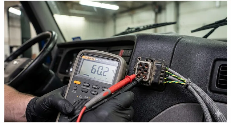
60 ohms ±5% — The path is clear. Both terminators are present and the backbone is intact.
20 ohms — You’re missing an end cap—or you have a break that looks like one. Trace the backbone and find the missing terminator or the open circuit—for a deeper dive into this specific fault pattern, see our guide on diagnosing a missing CAN bus terminator with a 120Ω reading.
40 ohms — Someone played ‘just add a resistor’ and you need to find it and yank it. You have three terminators.
Open circuit (infinite) — Both terminators are missing, or there’s a complete backbone break.
0 ohms (short) — CAN_H and CAN_L are shorted. Disconnect ECUs one by one until the short clears.
The Wiggle Test: While watching the resistance reading, gently wiggle the backbone harness at connectors, splice points, and anywhere the harness passes through a bulkhead. If the reading jumps or fluctuates, you have an intermittent connection—the hardest fault to find and the most common on older equipment.
Five Mistakes I See Over and Over Again
Mistake 1: The “Christmas Tree Effect.” I call this the ‘Christmas Tree Effect.’ A tech adds a green cap at the diagnostic port to fix a comm issue. It masks the real problem—maybe a corroded splice pack under the left frame rail. Next service, another tech sees a comm issue, adds another cap. I’ve pulled four of these caps off a single truck. The bus was at 30 ohms. The CAN transceivers were so overdriven they were running hotter than a hydraulic pump in stall. Measure first. Add termination only if you’ve confirmed it’s missing. This is a classic example of J1939 termination mistakes that lead to unnecessary ECU repair costs.
Mistake 2: Stubs that are actually backbone segments. A technician needs to add a new ECU. Instead of splicing into the backbone with a short stub, they cut the backbone, crimp a connector on each cut end, and plug both into a Y-splitter that connects to the new ECU. The Y-splitter’s branch becomes the stub—good. But the backbone is now interrupted by two connector interfaces, each adding contact resistance and potential failure points. Worse, some Y-splitters don’t maintain the twist in the pair through the junction, creating an impedance discontinuity. If you must cut the backbone, use a proper splice that maintains twist and impedance.
Mistake 3: Using the wrong cable. J1939/11 specifies shielded twisted pair with a characteristic impedance of 120 ohms. I’ve seen installations where someone used whatever twisted pair they had in the shop—Belden cable meant for RS-485, audio cable, even CAT5 Ethernet cable stripped and repurposed. None of these have the correct 120-ohm characteristic impedance. The bus will still work sometimes, especially if it’s short, but you’re operating outside the design margins. When the temperature changes or a nearby relay coil switches, you’ll get intermittent faults that don’t make sense. Always adhere to the correct J1939 cable shield, impedance, and jacket specification.
Mistake 4: Shield termination at both ends. This one is counterintuitive. The shield on a J1939/11 cable should be connected to ground at exactly one point—typically at the source ECU or a dedicated chassis ground near the network’s “center.” If you ground the shield at both ends, you create a ground loop. Current flowing through the chassis can induce noise on the shield, which capacitively couples to the signal wires. The symptoms look exactly like random J1939 communication faults that only happen when certain loads turn on—headlights, cooling fans, hydraulic pumps. I spent three days chasing this on a refuse truck once. The shield was grounded at the engine ECU and at a bulkhead connector in the cab. Disconnecting one shield ground fixed everything. For more on proper shielding practices, refer to our CAN bus shielding and filtering guide.
Mistake 5: Ignoring the 30-node limit. J1939 allows up to 30 nodes on a single backbone. That number comes from the electrical loading—each transceiver presents a certain capacitance and leakage current to the bus. Exceed 30 nodes, and the combined loading degrades the signal rise time and reduces noise margin. I’ve seen telematics installers add a gateway to a backbone that already had 28 nodes, assuming “one more can’t hurt.” It can hurt. If you need more than 30 nodes, you need a gateway architecture that segments the network into separate physical buses.
How to Know the Design Actually Works
Testing a J1939 backbone design isn’t just about measuring resistance and calling it done. I use a three-stage validation process that catches problems before they become field failures. Our CAN bus physical layer testing guide expands on these procedures.
Stage 1: DC verification. Measure the resistance between CAN_H and CAN_L with the network unpowered. Verify 60 ohms. Measure the resistance from CAN_H to ground and CAN_L to ground—both should be open circuit (or very high impedance). Measure continuity of the shield from end to end, and verify it’s grounded at only one point. These are table-stakes checks that take five minutes and catch 70% of issues.
Stage 2: Node discovery. Connect a J1939 scan tool or CAN analyzer and verify that every expected ECU appears on the address claim list. If a node is missing, check its stub length, its power supply, and its termination (if applicable). A missing node often indicates a stub that’s too long or a connector problem.
Stage 3: Bus loading and error frame monitoring. This is where most people stop, but it’s the most important step. Use a tool that can monitor bus loading percentage and error frame counts. On a healthy 250 kbit/s J1939 network, bus loading should stay below 50% during normal operation, with error frames approaching zero. If you’re seeing bus loading above 60-70%, you need to audit your message scheduling—some ECU is transmitting too frequently. If you’re seeing error frames, you have a physical layer problem even if the DC measurements looked good. Error frames indicate the CAN controllers are detecting bit errors and retransmitting, which consumes bandwidth and can eventually cause nodes to go bus-off.
I once validated a harness that passed DC verification with flying colors—60 ohms exactly, shield properly grounded, no shorts. But under load, the error frame counter was incrementing about once every ten seconds. The problem turned out to be a stub that was 1.8 meters long—just over the spec limit. At room temperature, it worked most of the time. But when the harness warmed up, the propagation delay increased slightly, and the reflection timing shifted enough to cause occasional bit errors. Shortening that stub to 0.4 meters eliminated the error frames entirely.
Components That Won’t Let You Down
The backbone is only as reliable as the parts you build it from. Over twenty-plus years of manufacturing diagnostic cabling and harness components for heavy-duty applications, I’ve learned that the difference between a harness that lasts ten years and one that fails in six months often comes down to three things: the connector series, the cable quality, and the termination method.
For J1939 backbones, Deutsch DT and HD series connectors are the industry standard for a reason. The DT series uses a wedge lock that prevents terminals from backing out under vibration, and the silicone seals actually keep moisture out—unlike some cheaper alternatives that claim IP67 but fail after a few thermal cycles. The HD30 series adds a flange mount option that’s essential for bulkhead pass-throughs. I’ve pulled Deutsch connectors out of trucks with 800,000 miles of salt-belt service and found the pins still clean and corrosion-free inside. For a deeper understanding of connector economics and maintenance, see our guide on Deutsch connector series selection and budget impact.
The cable itself matters more than most people realize. J1939/11 calls for shielded twisted pair with a drain wire, 120-ohm characteristic impedance, and a minimum of 12 twists per foot. Cut corners here and you’re building problems into the harness from day one. We source cable that’s specifically designed for CAN bus applications, with consistent impedance along the entire length and a jacket compound that doesn’t crack at -40°C or soften at +85°C. The cost difference between good cable and cheap cable is maybe 15% on the BOM. The difference in heavy duty network harness longevity is an order of magnitude. For extreme environments, consider our J1939 ArmorLink vibration-validated cable assembly.
Termination resistors themselves deserve more attention than they get. A proper J1939 termination resistor isn’t just a 120-ohm resistor soldered between two wires—it’s a sealed Deutsch connector cap with the resistor potted inside, rated for the same environmental conditions as the rest of the harness. We use 120-ohm resistors with 1% tolerance (the spec allows 5%, but we’re more conservative) and 0.5-watt power rating, potted in Deutsch DT or HD-series connector bodies. The resistor bridges pins A and C (CAN_H and CAN_L) in a 3-pin Deutsch configuration, or the appropriate pins in a 9-pin connector. Every single cap gets resistance-tested before it leaves the factory. I’ve found that about 1 in 500 caps fails this test—usually due to a cold solder joint that would have been an intermittent Deutsch DT termination cap failure in the field.
Frequently Asked Questions from the Field
What’s the actual difference between J1939/11 and J1939/15, and which should I use?
J1939/11 is the standard physical layer: shielded twisted pair, 250 kbit/s, up to 30 nodes, 40-meter backbone, 1-meter stubs. J1939/15 is the “reduced” or “light” version: unshielded twisted pair, still 250 kbit/s but only 10 nodes, still 40-meter backbone, but stubs can be up to 3 meters. Use J1939/11 unless you have a very specific reason to use J1939/15—the shielding makes a meaningful difference in electrically noisy environments like engine bays and hydraulic compartments. Allison Transmission, for instance, explicitly recommends against J1939/15 due to EMI susceptibility. For more on EMI mitigation in industrial settings, read our hardening OBD2 and J1939 for industrial EMI shielding solutions.
Can I run J1939 at 500 kbit/s?
Yes—J1939/14 specifies operation at 500 kbit/s. But the physical constraints change. At 500 kbit/s, the maximum backbone length drops to around 40 meters (same as 250 kbit/s under ideal conditions, but in practice you want to stay shorter), and stub lengths should be even shorter—I’d stay under 0.3 meters. The higher data rate is less forgiving of topology compromises. I see 500 kbit/s most often in marine applications and in newer off-highway equipment where higher data throughput is needed.
Why does the diagnostic connector sometimes show 120 ohms when the network seems to be working fine?
This usually means one of the termination resistors is inside an ECU that’s currently powered down or disconnected. Some engine ECUs, for example, only present their internal 120-ohm termination when they’re powered up. With the ECU off, you’re only measuring the external terminator at the other end of the backbone, so you see 120 ohms. This is normal for some designs, but it means your diagnostic procedure needs to account for it. Measure with the network powered and all ECUs communicating to get a true picture.
How do I add a diagnostic connector to an existing backbone that doesn’t have one?
Splice into the backbone with a stub no longer than 0.5 meters. Use a Deutsch DT 3-pin or 9-pin connector depending on what your diagnostic tools require. Do not cut the backbone and insert the connector in-line—that creates two additional connector interfaces and potential failure points. Splice the stub wires into the backbone conductors using adhesive-lined heat shrink crimp splices, and seal the splices against moisture. For common 9-pin issues, see 9-pin Deutsch connector diagnostic fix.
What’s the right way to handle a backbone that needs to pass through a bulkhead?
Use a bulkhead connector that maintains the 120-ohm impedance through the connector body. Deutsch HD30 series connectors with flange mounts are ideal for this. Avoid creating a stub at the bulkhead—the connector should be part of the backbone itself, not a branch off it. If you must use a bulkhead connector that creates a discontinuity, keep the total backbone length under 30 meters to give yourself margin.
My multimeter shows 60 ohms but I’m still getting communication faults. What’s next?
The DC resistance measurement only verifies termination—it doesn’t tell you about stub length, shield grounding, noise coupling, or signal integrity. Next steps: check stub lengths with a tape measure (yes, physically measure them), verify shield grounding at exactly one point, and look for any sources of electrical noise near the harness—relay coils, solenoids, VFD motor drives. If all that checks out, connect an oscilloscope and look at the CAN_H and CAN_L waveforms. You should see clean, square edges with the differential voltage reaching at least 1.5V during dominant bits. Rounded edges or low amplitude suggest excessive bus loading or impedance problems. A J1939 voltage drop field test can also reveal hidden resistance issues.
Can I use J1939 for communication between a tractor and trailer?
No—J1939 is designed for the vehicle’s internal network. Communication between tractor and trailer uses ISO 11992, which is a different physical layer and protocol, though it shares some conceptual similarities with J1939. Mixing these standards will result in communication failures and potentially damaged transceivers.
What happens if I accidentally swap CAN_H and CAN_L?
The network won’t work, but it generally won’t damage anything—CAN transceivers are designed to tolerate reversed connections. The differential voltage will be inverted relative to what the receivers expect, so they won’t recognize any frames. Some diagnostic tools will show “no communication” or “bus error.” Swap the wires back and everything should return to normal.
How often should termination resistors be replaced?
They’re passive components with no moving parts—in theory, they should last the life of the vehicle. In practice, I’ve seen them fail due to corrosion, vibration-induced cracking of solder joints, or physical damage to the connector body. If you’re chasing intermittent communication faults and everything else checks out, it’s worth unscrewing the termination caps and measuring them individually. They should read 120 ohms ±5%. If one reads open, high resistance, or significantly out of tolerance, replace it. At a few dollars per cap, it’s cheap insurance.
Is there any situation where I need more than two termination resistors?
No. The CAN bus physical layer is designed for exactly two termination resistors at the physical ends of the backbone. There are specialized applications where a “split termination” scheme is used (two 60-ohm resistors in series with a capacitor to ground at the center point), but that’s an advanced technique for noise-sensitive applications and not standard J1939 practice. For standard J1939 networks, two 120-ohm resistors, period.
The Difference Between a Network That Works and One That Works for a Decade
The spec tells you what’s allowed. Experience tells you what actually survives. A 40-meter backbone with 30 nodes and 1-meter stubs might pass validation on a bench at room temperature. Put that same network in a piece of equipment that operates from a Minnesota winter to an Arizona summer, with vibration, moisture, and the occasional pressure washer, and the margins start to disappear. For mining and heavy industrial applications where welding interference is present, review our mining welding interference case study on J1939 shielding.
The networks I’ve seen run for ten-plus years without a single communication fault share a few common traits: stubs are short (0.3 to 0.5 meters, not the full 1 meter), backbones are kept well under the 40-meter limit, connectors are Deutsch or equivalent quality, every splice is sealed and strain-relieved, and termination is verified at installation and documented. The networks that fail share the opposite: long stubs, daisy-chained connectors, random cable types, and termination that someone “thinks is probably fine.”
If you’re building a new harness or troubleshooting an existing one, start with the multimeter test. Measure the resistance. Then measure the stubs. Document what you find. The physical layer is not the most glamorous part of vehicle networking—there’s no cool software, no fancy algorithms, no dashboards full of metrics. It’s just copper, connectors, and physics. But get it right, and everything else just works. At its core, J1939 relies on the same differential signaling principles that make CAN bus resilient in noisy environments—master those fundamentals, and you’ll spend less time chasing ghosts. For a real-world example of how small termination errors lead to massive costs, see our J1939 $4000 phantom fault guide.
If you’re staring at a harness drawing wondering if that stub length is going to bite you in six months—or if you’re already chasing a ghost SPN—send over the details. We stock the correct 1% tolerance 120Ω Deutsch caps (the ones that don’t open up when the weather hits -30F) and we keep 20 years of these war stories on file. No sales pitch. Just tell us what the meter says and we’ll help you sort the backbone from the noise.
Technical specs and custom run inquiries: Contact us for technical support or custom harness inquiries
Urgent field issue? A quick photo of the diagnostic connector on WhatsApp usually gets you an answer within the hour: Chat with us on WhatsApp
CARSUN manufactures J1939 cabling, Deutsch connectors, and custom diagnostic harnesses under ISO 9001, IATF 16949, ISO 14001, and RoHS standards. 20+ years of direct factory experience. Every component 100% continuity and resistance tested before shipping.
