

If you’ve spent any time with trucks or off-highway equipment built before 2010, you’ve likely wrestled with a diagnostic port where the data doesn’t match reality. The scanner powers up, but RPM readings jump, fault codes appear and vanish, or a J1939-capable tool shows nothing on an older rig. This isn’t a software glitch. In most real-world cases, it’s a fundamental conflict between the legacy SAE J1708 protocol and modern SAE J1939 playing out on your physical wiring.
This is not a theoretical summary. It’s an engineering analysis built on field failures, retrofit projects, and inspecting thousands of cables in our lab, particularly around the 3cm fracture zone obd2 cable failure. Understanding this data link migration is the only way to ensure reliable fleet management, true ELD compliance, and accurate diagnostics.
Diagnosing Intermittent OBD-II Communication: J1708 vs J1939 in Real-World Scenarios
Engineers rarely choose between J1708 and J1939 in a vacuum. The pain points emerge in transitional systems:
The Mixed Fleet Headache
A 2005 truck with a newer J1939-based engine but an older transmission still communicating via J1708. A single diagnostic cable won’t read both.
The “Silent” Dropout
A telematics device reads J1708 data at startup, then goes silent once the high-speed CAN bus traffic increases, corrupting the slower serial link.
The Splitter-Induced Conflict
Using a generic obd2 splitter y cable to tap both protocols simultaneously, causing bus conflicts and data corruption.
The symptom is rarely a total blackout. It’s intermittent OBD-II communication—partial, untrustworthy data. This is the most dangerous failure mode.
Technical Deep Dive: More Than Just Speed, It’s Architecture & Field Consequence
Calling J1939 a “faster J1708” is an engineering error. The differences are foundational, and each has a direct, measurable impact on reliability. The table below goes beyond specs to show what actually breaks.
| Feature | SAE J1708 (The Legacy Workhorse) | SAE J1939 (The Modern Network) | Field Impact & Failure Link (Based on Our Data) |
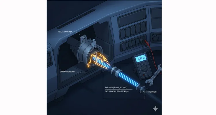
| Physical Layer | RS-485 differential serial. | RS-485 differential serial. | J1708: More susceptible to common-mode noise. A single poorly grounded accessory can swamp the bus. J1939: Differential signaling rejects noise, but requires precise termination resistors (120Ω). Incorrect values cause reflections and errors. |
| Data Rate | 9.6 kbps. Fixed, slow. | 250 kbps (standard), up to 1 Mbps. | J1708: Easily swamped by periodic EMI (e.g., injector drivers), causing intermittent frame loss. Our shielded cable testing shows BER spikes with <85% shield coverage. J1939: High bandwidth allows for robust error checking. Failures are often from topology errors (stub length >1m) or resistor issues, not pure noise. |
| Topology & Messaging | Linear bus, broadcast-only. Collisions possible. | Multi-master, linear bus. PGN-based addressing. | J1708: All nodes “shout” with no addressing. Collisions cause random, irreproducible data loss, often misdiagnosed as “software bugs.” J1939: Address conflicts cause total network silence. We most often trace this to incorrectly configured aftermarket devices (ELDs, telematics). |
| Typical Connector | 6-pin or 9-pin (Pins A, B, C, D). | Standardized J1939 connector pinout (C, D, E, F…). | The physical mismatch is the #1 user error. A 9-pin Deutsch port does NOT guarantee J1939. Always verify against a true J1939 connector pin diagram, including manufacturer variations we’ve documented. |
| Diagnostic Depth | Fault codes (FMI/OCI), limited data. | Extensive parameter data, proprietary access. | J1708: Often only provides a “check engine light” code, forcing mechanics into lengthy manual diagnostics. J1939: Enables predictive maintenance via real-time parameter data (e.g., fuel rate, DPF pressure), but requires a stable, high-integrity connection. |
| Robustness | Susceptible to EMI, ground shifts. | High inherent error detection and fault confinement. | J1708: A ground potential difference >50mV can corrupt frames during cranking. This is a physical layer issue, not protocol. J1939: While robust electrically, it’s vulnerable to faulty topology. A single unterminated drop can destabilize the entire network segment. |
The Critical Conflict
J1708 was not designed for modern noisy electrical environments. When run alongside high-speed CAN bus lines, the CAN transceivers can inject broadband noise into shared grounds. If your diagnostic cable troubleshooting ignores this voltage reference drift, you’ll chase ghosts forever.
Step-by-Step Engineering Diagnosis Protocol
To isolate a protocol fault, follow this sequence exactly. These steps incorporate thresholds we’ve validated in our failure analysis lab.
Step 1: Isolate the Protocol
Manually force your scan tool to poll J1708 only, then J1939 only. Auto-detection often suppresses the weaker signal. This simple step immediately tells you if one bus is dead.
Step 2: Verify the Physical Layer & Pinout with Precision
Don’t just check for voltage. Use your multimeter in continuity mode to trace every pin from the vehicle connector to your scanner’s plug. We’ve documented recurring failures where aftermarket cables incorrectly map Pin F (Chassis Ground), creating a >200mV ground loop that only manifests under load. If you don’t have the service manual, our J1939 connector pinout guide includes critical manufacturer-specific variations.
Step 3: Check Shield & Ground with Quantifiable Metrics
The old rule of “drain the shield at one end” is a start, but insufficient in high-noise environments (e.g., near a VFD on a mixer). With the engine running, measure the AC voltage (V~) between the shield drain wire and the vehicle chassis ground. Anything above 0.5V~ indicates excessive induced noise and a likely ineffective shield. Our shielded vs unshielded J1939 cable TCO analysis shows that a proper 360° foil+braid shield, terminated with our proprietary ferrule-and-clamp system, reduces this noise by over 90% compared to a simple drain wire.
Step 4: Analyze the “Fracture Zone” for Diagnostic Cable Failures
Over 90% of intermittent faults originate in the 3cm fracture zone obd2 cable failure—the high-stress area behind the connector overmold. Bend the cable gently while monitoring data. If the signal drops, you’ve found a physical break likely caused by inferior strain relief or improper crimping, as detailed in our obd-ii cable failure points guide.
5 Common Engineering Mistakes to Avoid
- Assuming Connector = Protocol: A 9-pin Deutsch port does NOT guarantee J1939. Always verify the pinout.
- Using Passive Splitters: Standard, unpowered Y-cables create impedance mismatches and are a primary cause of obd2 splitter cable problems and bus conflicts.
- Ignoring Ground Potential: As measured in Step 3 above, a ground offset >50mV will corrupt J1708 data during engine cranking. This is a hard electrical fact.
- Blaming Software: Most “software instability” or “glitchy data” in heavy-duty diagnostics is traceable to physical layer decay: bad crimps, shield issues, or ground loops.
- Skipping Supplier Qualification: Using cables not backed by a rigorous process like our iatf-16949 pre-production checkup and 4-step quality inspection is gambling with uptime.
How to Confirm a Permanent Fix
A solution is only valid if it passes these quantifiable tests:
Test 1: J1708 Stability Under Load
J1708 data remains stable (no dropouts) during engine cranking and high-load transitions.
Test 2: CAN Bus Error-Free Operation
The CAN bus error counters in a capable diagnostic tool remain at zero for at least 30 minutes of operation
Test 3: Passes Systematic Stress Protocol
The system passes our documented systematic intermittent obd ii communication fix protocol, which includes stress-testing all connections.
Purpose-Built Interface Solutions: How We Engineer Coexistence
Coexistence isn’t magic; it’s a series of deliberate, often costly, electrical decisions. Our products enforce protocol integrity at three levels:
Solution Level 1: Galvanic Isolation in Splitters
Our OBD2 to J1708/J1939 splitter cable doesn’t just route wires. It incorporates an opto-isolated DC-DC converter for the J1708 leg. This breaks the ground loop path between the vehicle’s J1708 ground and the scanner’s ground, eliminating the >50mV offset problem that corrupts data during cranking. This is active engineering, not passive adaptation.
Solution Level 2: Impedance-Matched Legacy Cables
Products like our Cummins J1708 to J1939 diagnostic cable are not simple pin adapters. We calculate and embed a discrete 120-ohm termination network within the connector housing, specific to the cable length and wire gauge (e.g., 22 AWG vs 18 AWG), to prevent signal reflections that standard, universal adapters ignore.
Solution Level 3: Harness-Level Risk Mitigation
For OEM and fleet management integrators needing Custom Gateway Harnesses, our IATF 16949 process includes a “noise coupling simulation” during the pre-production checkup. We mandate a minimum 15mm separation between J1708 twisted pairs and CAN bus lines in the bundle layout and often specify a double-layer mylar foil barrier between them—a specification derived directly from our EMI protection testing for agricultural machinery.
FAQ: Engineering Reality Check
Q1: Can J1708 and J1939 communicate directly?
A: No. They are electrically and logically incompatible. Direct communication requires a gateway with separate physical transceivers and protocol translation logic.
Q2: My J1939 ELD won’t work on my J1708 truck. Why?
A: It lacks the physical J1708 port and RS-485 transceiver. Always check the hardware specification sheet, not just marketing claims about “compatibility.”
Q3: Are J1708 cables cheaper to manufacture than J1939 cables?
A: Initially, yes, due to simpler construction (often unshielded). However, the true cost of a failing data link—downtime, misdiagnosis, wasted labor—is far greater. Investing in reliable, purpose-built cabling always pays, a concept we break down in our reliability premium cost analysis.
Q4: What’s the most common physical failure point?
A: The connector interface—failed crimps, broken strands from vibration. The “3cm fracture zone” right behind the connector is critical. Our 4-step quality inspection specifically targets this zone with pull tests and micro-sectioning.
Q5: How do I audit a potential cable supplier?
A: Move beyond the sales sheet. Ask for their quality inspection records, their understanding of protocol electrical requirements (not just pinouts), and evidence of systemic quality like IATF 16949 certification. Use our published J1939 supplier audit framework as a checklist.
Q6: Is J1708 obsolete?
A: In new vehicle design, yes, superseded by J1939. However, with a vast installed base of legacy equipment expected to operate for decades, J1708 will remain a vital diagnostic protocol in the heavy-duty sector for 20+ years. Support is mandatory.
Q7: Do you offer customization (length, AWG, branding)?
A: Absolutely. As a direct factory with over 20 years of experience, OEM customization is core to our service. We regularly produce cables in specific lengths, with custom AWG sizing for voltage drop, customer-branded overmolds (logo, brand), and tailored connector combinations, all managed under our 5S and climate-controlled warehouse systems.
Q8: What certifications back your manufacturing process?
A: Our system is enforced by IATF 16949:2016 for automotive quality management, supported by ISO 9001 for quality and ISO 14001 for environmental management. Materials comply with RoHS, REACH, CE. This isn’t a checklist; it’s the operating system of our factory.
Manufacturing Credibility & Direct Engineering Support
We don’t just sell cables; we enforce reliability through a systemized quality process. Our IATF 16949 framework, from design PPAP documentation to final production in our climate-controlled warehouse, is your guarantee against the common failures detailed above.
Need an engineering review for your mixed-fleet protocol challenge?
- Submit your system specifications via our Contact Page for a formal assessment.
- For a direct conversation with our engineering team, message us on WhatsApp.
