

We had a party the day the report came back. Clean sheet. The new ADAS camera module sailed through ISO 11452-2 with flying colors. Radiated immunity? Check. Field strength at 200V/m? No sweat. The lab in Stuttgart gave us the thumbs-up. We shipped the first batch to the assembly plant in Bavaria.
Three weeks later, the phones rang. Not with praise. With panic.
On the line, cars were being randomly kicked out of adaptive cruise control when passing under high-voltage power lines on the autobahn. In another instance, the lane-keep assist would glitch exactly when a trucker keyed up a CB radio in the adjacent lane.
That was the day the textbook hit the factory floor, and the textbook lost.
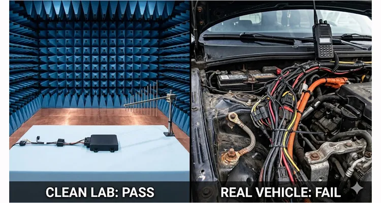
This is not a story about bad engineering. It’s a story about the gap between ISO 11452-2 and the real world—a gap wide enough to drive a truck through. And if you are designing or sourcing automotive electronics right now, you are standing on the edge of that gap whether you know it or not. After twenty years inside an IATF 16949 facility, we’ve learned that passing the lab test is just the price of entry. Staying reliable on the road is where the real engineering begins. As defined by the field of electromagnetic compatibility (EMC), true compatibility means functioning acceptably in the actual electromagnetic environment—not just inside a shielded room.
ISO 11452-2 Limitations: Why Lab Tests Don’t Match Real Vehicles
Let’s walk through where the standard test setup quietly rewrites reality. The ISO 11452-2 standard mandates testing in an Absorber-Lined Shielded Enclosure (ALSE). It’s beautiful in there. No noise. Perfectly calibrated antennas exactly one meter from the Device Under Test (DUT). The test harness is laid out with geometric precision on a non-conductive table.
But your car isn’t beautiful. It’s a mess.
Here is what happened to us, and what is happening to your components right now:
The Harness Lie
The standard calls for a “standard test harness”—typically 1.5 to 2 meters of unshielded wire, laid straight and proud on the table. In the real vehicle, that same wire is crammed into a conduit with four other high-current cables. It’s zip-tied to the chassis. It runs parallel to a PWM-controlled motor cable for 3 meters.
That bundle of copper we call a harness? In the RF world, we’ve watched it behave less like a controlled transmission line and more like a random length of conductor picking up every stray field within a quarter-wavelength. On our assembly floor, we stopped thinking of it as “wiring” and started treating it as an unintended receiving array.
In the lab, that 1.5m harness sits alone, proud, uncoupled. In the A-pillar, it’s pressed against a door speaker cable carrying 4A of PWM current. The parasitic coupling we measured afterward in our climate-controlled warehouse validation wasn’t just “different”—it was 18dB higher at 200MHz than our chamber model predicted. The RF coupling we saw in the lab was a gentle handshake; in the car, it’s a bear hug.
The Grounding Mirage
In the lab, the ground plane is a nice, solid copper sheet.
We chased one failure for three weeks before realizing the ground path ran through a spot weld that had oxidized during paint baking. At DC, it measured 2 milliohms. At 150MHz, it measured 47 ohms of inductive reactance. That bolt isn’t ground—it’s a frequency-dependent component nobody specified.
You can’t model a chassis ground as zero volts at RF. Every weld point, every crimp, every corrosion layer adds a complex impedance that changes with temperature, vibration, and time. Inside our ISO 9001 certified plant, we stopped calling it “ground” and started calling it “the reference plane that moves.”
The “Quiet” Terminals
We tested the module in isolation. Perfect. But in the car, that module is connected to a running engine, alternator, and a dozen other ECUs all switching inductive loads. The conducted noise on the power lines (which the ISO 11452-2 radiated test doesn’t fully simulate in the same way) mixed with the radiated field to create an intermodulation nightmare. The module wasn’t failing because of the field alone; it was failing because the field was modulating the noise already on the wire.
The Physics the Standard Forgot: It’s the Termination, Stupid
Diving into the failure analysis, we realized we had ignored a fundamental law of automotive EMC validation: the termination changes everything.
ISO 11452-2 does a great job of blasting RF at the Device Under Test (DUT). But the coupling mechanism in a vehicle is predominantly through the wiring harness. The standard assumes a specific, controlled impedance at the harness terminals. In reality, the termination impedances—the actual input/output circuitry of your sensors and actuators—are anything but standard.
Think of it this way: The RF energy couples onto the harness. That energy travels as a wave. When it hits the end of the wire (your DUT pin), it reflects based on the impedance mismatch. In the lab, that reflection is predictable. In the car, with connectors that are slightly corroded, or pins that have variable contact pressure, the Standing Wave Ratio changes.
We had a case where a camera would reset. The root cause? The impedance of the power pin changed by 15 Ohms due to a manufacturing tolerance in a third-party connector. This shifted the resonant frequency of the harness. Suddenly, the 400 MHz walkie-talkie frequency that should have passed through the module unnoticed was now perfectly coupled into the reset line. The module was ISO 11452-2 compliant with the “perfect” harness, but a failure with the “real” harness. That’s the kind of edge case our 4-step quality inspection is designed to catch before shipment.
The Step-by-Step Fix: How We Bridge the Gap (And How You Can Too)
After that autobahn fiasco—and the subsequent engineering review that lasted until 3 AM—we overhauled our validation philosophy. We stopped treating the standard as a pass/fail gate and started treating it as a baseline. Here is the five-step reality check we now run on every custom OEM build:
Step 1: The “Dirty” Harness Test
We take the standard ISO 11452-2 setup, but we swap the pristine test harness for a prototype of the actual vehicle harness. We run it through ferrites, zip-tie it to a grounded metal plate, and introduce crosstalk from adjacent “dummy” load wires. If the DUT passes in the chamber with the clean harness but fails with the dirty harness, we know we have a coupling problem, not a chip problem. This is where EMI troubleshooting vehicle harness issues begins, and the principles are similar to what we cover in our field guide to CAN bus EMI shielding.
Step 2: Impedance Sweep (The Black Art)
We use a Vector Network Analyzer (VNA) to characterize the actual input impedance of every pin on the DUT across the frequency range (1 MHz to 1 GHz). We don’t just test at 50 Ohms. We look for where the impedance dips or peaks dangerously. This tells us exactly which frequencies the real-world harness will “see” as a matched antenna. We’ve logged these sweeps for over 200 custom harness designs in our engineering database.
Step 3: The 15-Second Radar Rule
We ran a standard 2-second dwell at 1.3GHz. Passed. Then a Tier 1 asked us to run it for 15 seconds per frequency—their internal validation for radar exposure. At second 11, the power management IC hit thermal shutdown. The silicon was rectifying RF, heating up slowly, something the short pulse never revealed. We now run all radar-band tests to thermal equilibrium, not clock time. This aligns with industry recognition that dynamic operating conditions often reveal failure modes missed by static standard tests.
Step 4: Live Network Interference
We connect the DUT to a live, running vehicle network simulator. We induce voltage dropouts (CI 260) and transients on the power line while simultaneously blasting the RF field. This simulates the “alternator whine” mixing with the cell phone signal.
Step 5: The Three-Plane Reality
The standard requires testing the DUT in multiple orientations. We go further. We mount the DUT on a representation of its actual mounting bracket (with paint, bolts, and all). The bracket changes the ground reference and can act as a reflector, focusing energy in ways the foam stand in the lab never could.
Five Mistakes That Still Haunt Production Lines
I see these every time I visit a supplier’s factory. Avoid them.
1. Believing the “Calibrated” Antenna is the Only Source
We modeled a 5W handheld at 0.3m distance—near-field, complex impedance, not the 50-ohm far-field the chamber assumes. The field strength at the DUT was 3x higher than our calibrated antenna produced at the same forward power. The standard doesn’t lie, but it doesn’t warn you that a trucker’s CB at the window is electromagnetically closer than any test antenna.
2. Ignoring the HV Stuff
We measured 15A of common-mode current on an LV sensor cable routed 10cm from an 800V traction cable during hard acceleration. The field wasn’t coupled—it was induced. The LV ECU passed ISO 11452-2 alone, but with the HV system live, the CAN bus error rate hit 12% at 450MHz. The standard doesn’t require the HV system to be energized during LV testing. That’s the loophole. As recent industry analysis shows, the shift to EVs introduces new EMI challenges from e-drives that traditional component tests may not fully capture.
3. Using the Wrong Modulation
The standard uses AM modulation. Real-world threats include digital RF (LTE, Wi-Fi) with high peak-to-average power ratios. Your device might survive a sine wave but clip on a 4G signal.
4. Forgetting the Human
The standard doesn’t account for a hand waving near the antenna. The human body is a big bag of salt water and a decent conductor at some frequencies. It de-tunes everything.
5. Treating the Report as a Trophy
The ISO report is not a certification of “real-world readiness.” It’s a certification of “lab repeatability.” Don’t frame it. Read the fine print on the test setup and ask, “Is this my car?”
How to Know You’re Actually Fixed
You don’t find out on the assembly line. You find out in the “Hallway Test.”
After implementing the fixes—better filtering on the input pins, a revised grounding strategy, and a custom-length shielded cable—we went back to the field. We drove the car to a known high-EMI location (a truck stop with heavy CB radio usage). We took a handheld radio, keyed it up at various distances, and watched the oscilloscope on the CAN bus. For direct access to the network signals during this test, a J1939 9-pin pigtail breakout cable provides the cleanest probe points.
Our automotive EMC validation process doesn’t end with a pass/fail printout. We don’t sign off based on the automated report from the test house. We sign off when the field return rate drops below 50 ppm over six months. That graph from the $300k analyzer? It’s necessary, but it’s not sufficient. The only graph that matters is the one showing zero customer complaints.
At our IATF 16949 and ISO 9001 certified facility, operating under 5S management with 100% tested materials, we see these failures daily. That’s why we now offer this exact engineering deep-dive to our clients. Because we manufacture more than cables; we manufacture certainty.
Related Products for Your Real-World Build
If you are moving from the clean sheet to the dirty car, you need hardware that acknowledges the gap. Our OEM custom solutions are designed specifically to tame the chaos the standards don’t cover:
Custom-Length Shielded Cables
Avoid the resonance issues caused by excess cable slack. We cut, mold, and shield to your exact vehicle dimensions, using 100% tested materials stored in our climate-controlled warehouse. Proper automotive shielding effectiveness starts with getting the length right—and we’ve been getting it right for over twenty years. For a deeper dive into how we validate these designs, see our J1939 cable durability engineering guide.
Ferrite-Loaded Harness Assemblies
Pre-installed ferrite cores at critical terminations to kill common-mode currents before they enter your DUT.
HV+LV Composite Cables
Tested for crosstalk immunity, designed to separate the beast of high voltage from the fragility of sensor signals.
OEM-Spec Connector Overmolding
Ensuring that 15-Ohm impedance shift I mentioned? That happens in cheap connectors. We use IATF16949 graded materials and a 4-step quality inspection process to maintain signal integrity over a 20-year lifespan. Our 5S management ensures every crimp is repeatable, from prototype to production run. We’ve also documented how this contrasts with less reliable methods in our crimp vs solder vibration reliability termination guide.
FAQ: The Post-Lab Reality Check
Q: If my device passes ISO 11452-2, why would it fail in the vehicle?
A: Because the standard tests the device. The vehicle tests the system. The harness, the grounding, and adjacent electronics in the vehicle create a unique electromagnetic environment that cannot be fully replicated in a component-level ALSE test. This is the core challenge of automotive EMC validation.
Q: What is the most common real-world interferer that the standard underestimates?
A: Hand-held transceivers (CB radios, walkie-talkies) and the new wave of high-power digital communication (5G mmWave). They produce near-field effects and modulations that simple continuous wave (CW) testing misses. For a real-world example, see our mining welding interference case study.
Q: Does cable length really matter for EMI immunity?
A: Absolutely. A cable that is a quarter-wavelength long at a specific frequency becomes a perfect antenna. We always recommend using the actual vehicle harness length in validation, not the standard 1.5m lab harness.
Q: What is “intermodulation” and why should I care?
A: It occurs when two different frequencies (e.g., a radio signal and a switching power supply noise) mix in a non-linear component (like a semiconductor junction), creating a third, unwanted frequency that interferes with your circuit.
Q: How does an electric vehicle’s HV system affect LV immunity?
A: The HV cables act as transmitting antennas. They can induce significant currents into nearby LV harnesses. You need to test LV components with the HV system active and loaded to ensure immunity.
Q: Are OEM standards (like GMW3097 or FMC1278) harder than ISO 11452-2?
A: Yes. Understanding OEM EMI requirements vs ISO is critical—they often add specific requirements like the 15-second radar dwell times and specific functional performance status (FS) criteria that are much stricter than the general ISO pass/fail.
Q: Can a connector cause an EMI failure?
A: Yes. A poor contact or high resistance in the shield connection of a connector can turn a shielded cable into an unshielded antenna. The impedance discontinuity at the connector is a major weak point.
Q: What is the first thing you check when a passing module fails in the car?
A: The ground. Specifically, the RF impedance of the ground path. A DC ground is not an RF ground.
Q: Does RoHS compliance affect EMI?
A: Indirectly. Some RoHS-compliant solders and materials have different high-frequency characteristics than legacy tin-lead mixes. It’s rare, but we’ve seen it affect passives in filter circuits. All our materials are RoHS, REACH, and UL compliant for consistency.
Q: Can you help if my design is failing real-world tests?
A: That’s our primary work. We don’t just sell cables; we analyze the failure, redesign the harness layout, shielding, or filtering, and build the custom solution that makes the car work. Our engineering team has been doing this for over two decades. If you’re facing intermittent issues, our guide on how to diagnose intermittent CAN bus failures is a good starting point.
Got a ghost in your machine? An EMI issue that the lab can’t replicate but your drivers complain about weekly? Let’s talk engineering.
Chat with Linda on WhatsApp for OEM Engineering Support
Send us your Test Report for a Free Real-World Gap Analysis via our Contact Page
