

Last Thursday, I got a call from a fleet maintenance director in Alberta. He was calm, but I could hear the edge in his voice. They had a 2023 Kenworth T680 glider kit—brand new engine, the whole nine yards—sitting dead in the yard with a no-start condition. No codes on the dash, but the J1939 data stream was gone. Their lead tech had already swapped two ECMs, a wiring harness section, and about fourteen hours of labor. The bill for parts alone was pushing $3,500, and the truck still hadn’t moved an inch.
He asked me to look at the photos of the diagnostic port. I zoomed in on the Deutsch HD10-9-1939 connector. The first thing I noticed? The socket cavities looked clean, but the center pin—Pin C, the J1939+ shield—had a faint, almost invisible hairline crack at the solder joint where it met the backshell. I’ve seen this exact failure mode dozens of times over 20 years in the factory.
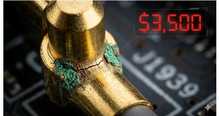
This article is about that $3,500 mistake. It’s not about the ECM, the software, or the sensors. It’s about the 75-cent component—the Deutsch 9-pin connector—that brought a half-million-dollar machine to its knees, and how to make sure it doesn’t happen to you.
The Typical Scene: When Communication Dies
You’re hooked up to a late-model Class 8, the ignition’s on, and your software—whether it’s Cummins INSITE, Detroit Diesel Diagnostic Link, or a generic RP1210 tool—just sits there. The status bar freezes at “Establishing CAN Link” or, worse, it throws a generic “User Defined Fault Code: 9” that points you nowhere. The engine’s ECU is alive (you can hear the relays clicking), but the data pipe is dead. That’s the ghost we’re chasing.
The natural instinct is to blame the software, the adapter, or the main ECU. But in my experience, when the power and ground are solid (Pin A = battery, Pin B = chassis ground), and you still can’t talk to the network, the problem is often physical. And the weakest physical link in the heavy-duty diagnostics chain is the Deutsch 9-pin connector itself. We’ve documented countless cases where technicians fell into the trap of misdiagnosing these issues—a problem we explored in detail in our guide on how to diagnose intermittent CAN bus failures.
The Root Cause: Why Deutsch 9-Pin Connectors Fail
Deutsch connectors earned their reputation in military applications, handling vibration and harsh environments better than most. The HD10-9-1939—the standard 9-pin diagnostic port—is engineered for durability. But durability has limits. Here’s what we’ve documented in our failure analysis lab at the factory after examining hundreds of field returns.
1. The Pin Crimp and Solder Joint Failure
The most common failure hides inside the connector’s backshell. The pins are crimped to the wires, but in many aftermarket and even some OEM-installed connectors, the crimp lacks the gas-tight seal required for long-term reliability. Over years of thermal cycling (-40°C to +125°C) and vibration, the copper wire work-hardens and fractures precisely at the crimp barrel. The shield connection (Pin C) is especially vulnerable—it carries no DC current, so a poor connection escapes detection until high-frequency CAN signals get scrambled and the tool drops offline. The debate between crimp and solder is settled in our environment—we’ve published our findings on why crimp vs solder vibration reliability favors cold-weld terminations for exactly this reason. Our production floor rejects any termination that doesn’t meet our pull-test standards.
2. Cavity Contamination and Fretting Corrosion
We pull apart failed connectors in our ISO 17025 lab and regularly find fretting corrosion on the male pins of the mating cable. Constant plugging and unplugging, combined with micro-vibration, wears away the tin or gold plating. Exposed base metal oxidizes, creating an insulating layer that behaves like a resistor. Your diagnostic tool might supply enough voltage to power up, but the 2.5V differential CAN signal gets eaten by that contact resistance before it reaches the transceiver. We’ve measured contact resistance increases from 5 milliohms to over 100 ohms in advanced cases—enough to kill any data communication.
3. The “Green Death” – A Case of Capillary Action
This is the silent killer, and we see it most often in cables that failed our 100% dielectric strength test. It starts when the rear grommet—usually a low-quality one that doesn’t meet our IP67 specs—fails. According to the IEC 60529 standard, IP67 requires passing a 1-meter immersion test for 30 minutes, but capillary action can bypass sealing long before visible water ingress occurs. Water doesn’t just drip in; it gets pulled in by capillary action, traveling inside the insulation, underneath the crimp, and into the pin cavity. Under our microscope, we watch copper conductors transform from bright alloy to black copper oxide or green carbonate corrosion products. Resistance jumps from milliohms to kiloohms instantly. You can’t see it from outside the connector, but our testers catch it every time during final inspection.
Step-by-Step: Diagnosing a Deutsch 9-Pin Failure
Before you replace an ECU or a $1,200 wiring harness, run this physical inspection. It takes ten minutes and requires only a multimeter and a bright light. This process follows the same logic we outlined in our comprehensive 9-pin Deutsch connector diagnostic fix guide
Step 1: Visual Inspection – The Obvious
- Look at the receptacle (the port on the truck). Are any of the 9 socket cavities deformed, spread open, or missing?
- Shine a light inside. Is there green dust, mud, or oil residue?
- Check the mating plug on your diagnostic cable. Are the pins straight? Is the plastic shroud cracked?
Step 2: The Pin-Tension Test (Our Shop Floor Method)
Grab a spare male Deutsch pin—we use the ones from our HD10-9-1939 assembly kits, which are machined to exact OEM tolerances, not the stamped economy versions. Insert it into each of the 9 female sockets on the truck. A healthy socket, fresh from our climate-controlled warehouse, requires about 3-4 lbs of insertion force. You’ll feel a distinct “click” and the pin should require a firm tug to remove. If the pin slides in like a needle into butter, or falls out when you turn the connector over, that socket is fatigued. That’s your intermittent connection source.
Step 3: Continuity and Resistance Check (The Critical Test)
- Set your multimeter to ohms.
- Probe between Pin A (Battery) on the truck connector and the positive terminal of the battery. You should see less than 0.5 ohms.
- Probe between Pin B (Ground) and the chassis negative. Same spec.
- Now, the most important test: Probe between Pin C (CAN Shield) and chassis ground. You are looking for a very low resistance, ideally less than 1 ohm. If you see an open circuit (OL) or high resistance, the shield is floating.
- Per CAN bus troubleshooting standards, the resistance between CAN High and CAN Low should read 55–65 ohms with the network powered off, indicating proper termination. But the shield path must be near zero.
If the shield is open, this will absolutely wreck J1939 communication, causing phantom errors and “no-comm” conditions. This was the $3,500 mistake on that Kenworth—the shield wire had corroded through inside the harness jacket, 6 inches behind the connector.
Common Diagnostic Mistakes I See Every Day
“It’s a Software Problem” – Re-flashing the ECU or updating the laptop before verifying physical layer integrity. You can’t flash through a broken wire. I’ve watched teams waste days on software reloads when the real issue was a $4 repair. One fleet in Nebraska spent six weeks and $12,000 on consultant fees before discovering a corroded Deutsch 9-pin connector was the culprit.
“The Cable is New, It Can’t Be Bad” – I’ve tested “new” aftermarket cables that arrived with cold solder joints on the Deutsch pins. We reject about 2% of incoming raw connector stock here because of manufacturing defects. New doesn’t mean good. In one case, a fleet replaced three ECUs before discovering the brand-new diagnostic cable had intermittent continuity—a problem we see often enough that we published a J1939 cable agriculture survival guide for exactly these environments.
Ignoring the Shield (Pin C) – Many techs check power and ground with a test light, but ignore the shield. In a properly functioning J1939 network, the shield is tied to ground at one point to drain induced noise from the alternator and AC compressors. If it’s open, your CAN waveforms—when viewed on a PicoScope—look less like clean square waves and more like a heart attack on an EKG, with rounded edges and voltage spikes.
How to Confirm the Repair is Successful
You’ve replaced the connector, repaired the wire, or installed a new OEM-grade cable assembly. How do you know it’s fixed?
- Visual Confirmation: New connector, clean pins, proper backshell sealing with heat shrink and adhesive lining.
- Mechanical Confirmation: The mating cable clicks firmly and doesn’t wiggle.
- Electrical Confirmation: Re-run the resistance checks from Step 3. Pin A to battery: <0.5 ohms. Pin B to ground: <0.5 ohms. Pin C to ground: <1 ohm. Verify CAN High to CAN Low reads 55–65 ohms with all power off.
- The Oscilloscope Test (If Available): Look at the CAN High and CAN Low signals on Pins E and F (or J1939+ and J1939- depending on pinout). They should be clean square waves, not rounded or noisy. If you fixed the shield, the noise floor should drop significantly.
The Factory View: What Makes a Connector Last 20 Years
At our facility, we’ve been making these cables since 2005. We see the difference between a connector that lasts 10,000 hours in a coal mine and one that fails in six months in a municipal fleet. It comes down to manufacturing discipline—the kind required to maintain our IATF 16949 certification. We documented our journey and what it means for customers when we achieved IATF 16949 certification, moving beyond simple compliance to true process control.
Here’s what we do differently, guided by our ISO 9001, IATF 16949, and ISO 14001 management systems:
- Raw Material Sourcing: We use only virgin, RoHS-compliant plastics and contacts plated to spec. We don’t use recycled materials that can shrink or crack. Our ISO 14001 certification ensures our environmental management matches our quality commitment.
- Crimp Quality: Under IATF 16949, our crimp quality isn’t a guess. Every machine is calibrated weekly, and we perform pull-tests on samples every shift, logging the data for full traceability. A proper crimp, to us, is a cold weld between wire and contact.
- 100% Electrical Testing: Every assembly goes through a 100% test—continuity, shorts, and dielectric strength. Not sample testing. 100%.
- Environmental Control: Our assembly area is climate-controlled and follows 5S management. Humidity and temperature swings affect materials. We control them.
- Full-Plastic Design: We spec connectors with full-plastic shells and proper backshells to prevent the capillary action that leads to the “green death.”
Related: Choosing the Right 9-Pin Solution for Diagnostics
When you need to replace a faulty Deutsch 9-Pin connector or cable, you have options. But not all are created equal. For heavy-duty diagnostics, you need a component that matches the vehicle’s electrical architecture. The confusion between Type I and Type II connectors alone has cost fleets thousands—we broke down the differences in our detailed J1939 Type 1 vs Type 2 guide after watching a Midwest fleet lose $5,000 to this exact mistake.
Here’s a quick reference on common 9-Pin J1939 types and their applications:
| Type / Shell Color | Typical Application | Key Feature | Common Failure Point |
| Type I (Green Shell) | Off-Highway, Ag, Construction (Caterpillar, John Deere) | Direct J1939 access, often used for datalink | Shield pin (C) corrosion from environmental exposure |
| Type II (Black Shell) | On-Highway Trucks (Freightliner, Volvo, Mack, International) | J1939 + J1708 combined, standardized by TMC | Worn sockets from frequent plugging/unplugging |
| OEM Custom (Various) | Specific brands (e.g., some Agco, Doosan) | May have non-standard pinouts for proprietary data | Pin misalignment, incorrect wiring from aftermarket replacements |
Choosing the correct physical connector is step one. Ensuring it’s built to withstand the environment is step two. For field repairs where the connector body is intact but the pigtail is damaged, a J1939 9-pin pigtail breakout cable can restore the connection without a full harness replacement. We offer OEM customization on all these—you can specify your logo, brand, cable length, jacket color, and even the exact AWG needed for your application. Whether you need a standard J1939 9-Pin Cable or a custom adapter for a legacy machine, the engineering principles are the same.
FAQ: Deutsch 9-Pin Connector Failures
Q1: My diagnostic tool powers up but says “No ECU detected.” Is this a connector issue?
A: Possibly. Power can travel through a poor connection that data cannot. The CAN signal is low-voltage and high-speed. A bad pin contact might pass 12V for power but completely block the 2.5V CAN signal. Check the pins mechanically first. This is the most common scenario we address in our OBD2 port no communication fleet manager guide.
Q2: What is the most common pin to fail in the Deutsch HD10-9-1939?
A: Pin C (shield) and Pin A (power) are the most common. Pin C fails due to corrosion at the termination point. Pin A fails because it carries continuous current, leading to thermal stress over time.
Q3: Can I repair a Deutsch connector myself, or should I replace the whole harness?
A: You can replace the individual contacts if you have the proper Deutsch crimp tool (HX4 or similar). However, for the 9-pin diagnostic receptacle, it’s often molded into a harness. If the cavity plastic is cracked or the locking tang is broken, you must replace the entire connector or the harness section.
Q4: How do I prevent “wicking” and internal corrosion?
A: Use connectors with proper rear grommets and seals. When repairing, use adhesive-lined heat shrink over the backshell to create a moisture-proof seal. Ensure the cable jacket is cut cleanly and isn’t damaged.
Q5: What does the shield pin (Pin C) actually do?
A: It connects the foil or braid shield inside the J1939 cable to the vehicle’s chassis ground. This drains induced electrical noise away from the data lines. Without it, the CAN transceivers struggle to interpret the data, leading to errors. For a deeper dive, our field guide to CAN bus EMI shielding explains the physics in detail.
Q6: My connector looks clean, but the connection is intermittent. What’s happening?
A: Intermittent = mechanical. You likely have a spread socket in the receptacle or a bent pin on the cable. The physical contact is made and broken by vibration. Use the pin-tension test described above.
Q7: Does the color of the Deutsch shell matter (Green vs. Black)?
A: Yes. It’s not just for looks. While the pin layout is physically the same (9-pin), the shell color often denotes the wiring standard per TMC RP1211. Black usually indicates a J1939/J1708 combo port for on-highway. Green is often just J1939 for off-highway. Always verify the pinout against the vehicle schematic.
Q8: Are cheaper aftermarket 9-pin cables a common failure point?
A: Yes. We’ve seen aftermarket cables fail because of poor-quality pins with insufficient plating thickness, and incorrect crimping that damages the wire strands. This is why we maintain RoHS and CE certifications and test everything in-house.
Q9: What is fretting corrosion, and how do I spot it?
A: It’s microscopic wear on the contact surface caused by vibration. You can’t always spot it without magnification, but it appears as a dull, grayish freckling on the bright pin surface. It increases resistance dramatically.
Q10: How often should Deutsch diagnostic ports be inspected?
A: In a severe-duty environment (construction, mining), inspect the connector visually every time you plug in. Perform a full electrical continuity test on the pins at every major service interval (250-500 hours).
Need a Reliable Solution or Custom Engineering?
If you’re designing a new diagnostic tool, building a custom harness, or simply tired of chasing phantom communication faults caused by sub-par connectors, we can help. We’re not just a cable supplier; we’re an engineering partner with 20+ years of direct factory experience and certifications including IATF 16949 and ISO 14001 that back every claim we make.
We offer:
- OEM Customization: Your brand, your specifications, your packaging.
- Engineering Support: We help you select the right materials and pinouts for your specific application. For fleet-wide solutions, explore our complete range of truck cables designed for heavy-duty environments.
- Certified Quality: All products are built in our ISO 9001, IATF 16949 certified facility, with full traceability and 4-step quality inspection.
Stop guessing. Start diagnosing with confidence.
Chat with our engineering team on WhatsApp for immediate technical support or to discuss your custom project:
Message us on WhatsApp
For detailed project specifications or to request a custom quote, please visit our Contact Page:
Contact Our Engineering Team
