

You swap a CAN bus sensor, check the 120Ω terminator, even bypass the suspected wiring harness. The fault—usually something vague like “CAN Bus Off” or “ECU Timing”—clears up for a test drive, only to return as soon as the machine works up a sweat. Everyone blames the welder first. And sure, a guy on night shift with a cheap arc welder and long leads draped over the harness can absolutely fry a control system. We’ve documented this exact scenario in our mining welding interference case study.
But what about the ghost that shows up only when the operator engages the high-flow hydraulics? Or the comm loss that happens at exactly 1,500 RPM on the haul road—every single time?
I’ve spent the last 20 years on the factory floor building custom harnesses and another decade in the field chasing faults that left entire service teams scratching their heads. The hardest ones to catch aren’t the welders. They are the “always-on” sources of electromagnetic interference (EMI) that we accidentally design into the equipment ourselves. The discipline of ensuring equipment functions correctly in its electromagnetic environment is formally known as electromagnetic compatibility (EMC), and it’s where most of these ghosts are born. For a deeper dive into how we approach these problems, check out our field guide to CAN bus EMI shielding. These five uncommon EMI sources in heavy equipment—from VFDs to service truck inverters—are the ones that don’t show up in any manual.
Here are five less-obvious EMI culprits that are silently sabotaging your heavy equipment diagnostics and how to catch them red-handed.
1. The VFD That Talks Too Loudly: Variable Frequency Drive Interference on CAN Bus
We are seeing Variable Frequency Drives (VFDs) on everything now—from electrically driven hydraulic pumps on excavators to cooling fans on Tier 4 Final power modules. I specify VFDs on almost every new build now—they save fuel and give you variable speed control that hydraulics can’t touch. But every time I walk onto a site with a new electric excavator, I pack extra ferrites. Because VFDs don’t just drive motors; they broadcast noise. Our J1939 ArmorLink vibration-validated cable assemblies are specifically designed to survive in these environments.
The Scene
You have a diesel engine, a generator, and several electric motors controlled by VFDs all on one piece of mobile equipment. The CAN bus network (J1939 or CANopen) is running at 250kbps. In the yard, the display cycles through menus just fine. But take it into the cut, spool up the electric drive, and the screen doesn’t just error out—it reboots. Hard. Like someone pulled the key out and shoved it back in. You check the backbone resistance, verify the drop cables, and test the grounds. Everything reads normal on the multimeter.
The Technical Breakdown
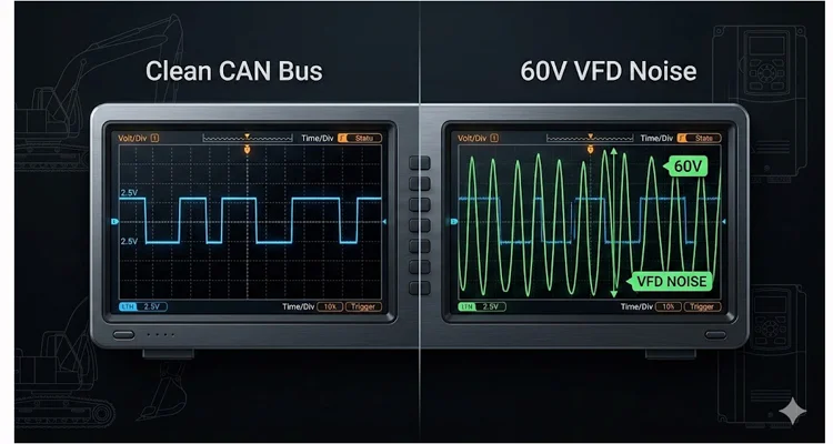
A VFD doesn’t smoothly give power; it slams it on and off thousands of times a second using pulse-width modulation. That slamming action doesn’t just spin the motor—it launches energy everywhere. We call it common-mode noise on paper, but in the truck, it feels like the whole electrical system is vibrating at a frequency you can’t see. Here’s where the design mistake happens: someone bundles the CAN cable with the VFD motor leads or shares the 24V power supply between the VFD and the logic controllers without isolation. The CAN bus protocol was designed with differential signaling specifically to reject this kind of noise, but when you dump 60V onto the lines, even differential pairs can’t save you. If you’re trying to diagnose intermittent CAN bus failures, start by looking at cable routing.
I flew out to a logging operation in the Pacific Northwest for this one. The skidder would run for 20 minutes, then just drop dead electronically. The operator was ready to push it off a cliff. We traced it to the VFD for the electric drive motor. When we put a differential probe on the CAN_H and CAN_L lines, we weren’t seeing the clean 2.5V recessive and 1.5V dominant signals. We were seeing a 60V peak-to-peak sine wave riding the CAN lines. To put that in perspective: the CAN transceiver is trying to read a 2V difference. We were asking it to hear a whisper in a hurricane. This is classic VFD interference CAN bus destruction.
Step-by-Step: How to Kill the VFD Ghost
- Isolate the Power Supply: Do not daisy-chain 24V power from the VFD’s control terminals to the PLC or Display. Use a dedicated, isolated power supply for the logic side. In our shop, we spec Mean Well or similar medically isolated supplies for this exact reason.
- Check the CAN_GND: This is the most common mistake I see in OEM designs. In a mixed-voltage system (like AC VFDs and DC controls), CAN_GND must be connected to the battery negative, NOT to chassis ground at the VFD. If the VFD creates a ground potential rise, it will shove that voltage straight down your CAN shield if it’s grounded there. Understanding the J1939 connector pinout is critical here.
- Separate the Cables: CAN bus cable must be at least 300mm away from VFD output power cables. If they must cross, do so at a 90-degree angle. I carry a set of cable spacers in my kit specifically for this.
- Ferrite Beads: On the power input to the VFD and the motor output leads, install high-frequency ferrite beads (like Fair-Rite #31 material, not the generic ones from old monitors) to suck up the nasty switching noise before it radiates.
2. The Dirty Generator: “Clean” Power Doesn’t Exist in the Field
When a machine is on a jobsite, it’s often plugged into a portable generator for testing or for powering auxiliary electric components. Generators are supposed to be “isolated” from the grid, so they must be clean, right? Wrong. I’ve learned to treat every jobsite generator as guilty until proven innocent. For a real-world example, our mining welding interference case study covers similar ground noise issues.
The Scene
You are doing a final diagnostic calibration on a new forestry attachment. The machine is plugged into a 100kW jobsite generator. Everything powers up, but the CAN-based joysticks are jittery. The calibration fails intermittently, throwing a “Signal Invalid” error. The software points to a sensor, but the sensor tests fine on the bench.
The Technical Breakdown
Many portable generators, especially the “contractor grade” ones from rental fleets, are not designed for sensitive electronics. They often have floating grounds or bonded neutrals that create a ground loop when connected to the equipment’s chassis. Furthermore, the waveform from an inverter generator isn’t a perfect sine wave; it’s a simulated sine wave full of high-frequency harmonics. These harmonics ride the ground line back into your sensitive diagnostic tool or the machine’s 12/24V rectifier, causing havoc on the controller area network.
I once spent two days chasing a calibration fault on a prototype feller buncher. It only happened at the customer’s site. We brought it back to the shop, and it worked perfectly. The only difference? The shop had a bonded-earth ground rod driven into the floor. The site had a portable generator sitting on gravel. The generator’s floating neutral allowed the chassis voltage to float relative to earth, creating a 40V AC potential between the machine frame and the ground. When we connected the diagnostic laptop (which was grounded via its charger), that connection created the ground loop that killed the CAN bus. The generator was the antenna, and our laptop was the path to ground. This is exactly why we developed our hardening OBD2 J1939 industrial EMI shielding solutions.
Step-by-Step: How to Fix Generator Noise
- Bond the Neutral: If using a portable generator, ensure it is configured with a bonded neutral (NEC required for most portable applications) to provide a stable reference. Carry a bonding plug in your diagnostic kit.
- Isolation Transformer: For sensitive diagnostics, use an isolation transformer between the generator and your equipment or laptop charger. I use a small 300VA medical-grade isolation transformer for flashing ECUs.
- Laptop on Battery: Never plug your diagnostic laptop into the AC mains when connected to equipment powered by a questionable generator. Run the laptop on internal battery to break the ground loop. This one habit has saved me more times than I can count.
- Check Chassis Voltage: Measure AC voltage between the machine chassis and a known earth ground rod. Anything over 5V AC is a red flag. If you see 10V or more, stop diagnosing and fix the power source first.
3. The “Quiet” Hydraulic Pump Drive (Grundfos / Parker / Danfoss)
Hydraulic pumps are mechanical. They can’t cause electrical noise, right? Not anymore. With the rise of electro-hydraulic systems and integrated servo drives, the hydraulic pump is often a major EMI source hiding in plain sight. I’ve pulled more hair out over pump drives than any other component. Our J1939 cable agriculture survival guide covers similar challenges in farming equipment.
The Scene
A concrete pump truck with a CAN-based remote control. The remote works fine when the pump is idling, but as soon as the operator demands high pressure to pump concrete, the remote disconnects. The radio link is fine—you can stand right next to the machine and watch the disconnect happen—but the CAN interface inside the pump control box crashes.
The Technical Breakdown
Modern hydraulic pump controllers (like Danfoss PVG or Parker IQAN) are essentially VFDs or servo drives in disguise. They use PWM to control the proportional valves. If the high-current PWM wiring for the valves is not properly shielded and separated from the CAN bus wiring inside the control panel, you get PWM crosstalk. The steep edges of the PWM signal (high dV/dt) capacitively couple onto the CAN bus lines. This doesn’t look like a classic short circuit; it looks like bit stuffing errors or CRC errors on the protocol level. The software says “communication error,” but the hardware is physically bleeding noise into the data lines. Understanding the difference between J1708 vs J1939 protocol comparison helps, but the physical layer is where the real problems live.
In one instance on an offshore drill rig, the hydraulic pump would run fine for 10 minutes, then drop the CANopen network. The maintenance team replaced controllers, cables, and sensors—three rounds of parts, thousands of dollars, same problem. The issue was the PWM cables to the pump solenoids. They were routed in the same fiberglass cable tray as the CAN bus. The heat and vibration softened the cheap PVC insulation on the solenoid wires, reducing the dielectric strength, and allowing the PWM pulses to arc across to the CAN lines inside the tray. We rewired with separate trays and the problem never returned. This is a classic example of why we emphasize cold weld vibration arbitration in our designs.
Step-by-Step: Separating Power from Signal
- Enforced Separation: Mandate that PWM solenoid cables must be in a separate conduit or on a separate cable tray from CAN bus cables. If they must share a tray, install a grounded metal separator. This isn’t a suggestion; it’s a specification requirement.
- Twisted Pair Discipline: Ensure the PWM power leads are tightly twisted (at least 3-4 twists per foot) to cancel the magnetic field. Loose twisting turns the cable into an inductor.
- Shield Termination: Ensure the shields on the CAN bus are terminated with a low-impedance connection (360-degree clamp, not a pigtail) to the backshell of the connector. That inch-long pigtail acts as an antenna at VFD frequencies. Our crimp vs solder vibration reliability termination guide explains why proper termination matters.
4. The Invisible Antenna: Unshielded Differential Pressure Sensors
We trust our sensors. We plug them in, they give a value. But a sensor isn’t just a transducer; it’s an antenna. And a plastic-bodied sensor with unshielded internals is a very effective one. For more on sensor-related failures, read our forensic guide to reefer wiring harness failure.
The Scene
An engine starts surging randomly. The diagnostic code points to the Fuel Rail Pressure sensor. You replace it, and it’s fine for a day. The code comes back. You scope the sensor signal (usually 0.5-4.5V analog), and it’s clean on the bench. But the CAN bus is still reporting implausible pressure data when the engine is running.
The Technical Breakdown
This is a “common mode” issue that doesn’t show up on a single-ended scope probe. Many pressure sensors have a plastic body and unshielded internal electronics. The sensor wire runs back to the ECU. The sensor body itself acts as an antenna. When the alternator kicks in or a high-current fan clutch engages, RF energy is dumped into the engine bay. That RF energy hits the sensor body, travels down the signal wire, and enters the ECU. The ECU sees the noise on the 5V reference line or the signal line and interprets it as a data spike. If that spike occurs during a critical moment of CAN message arbitration, it corrupts the data frame.
I had a case with a Tier 4 diesel where the DPF regeneration cycle would cause the engine to derate. The culprit was the Differential Pressure Sensor across the DPF. It was mounted directly to the hot, vibrating exhaust, and its unshielded case picked up the RF from the turbo speed sensor running at 100,000 RPM. The solution wasn’t a new sensor; it was wrapping the sensor in copper tape and grounding it to the block. A crude fix, but it proved the point to the OEM, who later revised the sensor specification. Our IATF 16949 PPAP zero-defect cable process ensures this doesn’t happen with our harnesses.
Step-by-Step: Sensor Noise Hunting
- The “Wrap Test”: Temporarily wrap the suspect sensor in aluminum foil and ground the foil to the engine block with a short jumper. If the fault disappears, you have an unshielded sensor problem. I keep a roll of HVAC foil tape in my truck for this exact test.
- Ferrites on Sensor Wires: Add a split-core ferrite bead on the sensor wires as close to the ECU as possible. The #31 material works here too, but match it to the noise frequency.
- Specify Metal-Bodied Sensors: For critical applications (like pressure after a DPF), specify sensors with a metal body that can be directly grounded to the chassis, creating a Faraday cage around the element. It costs a few dollars more but saves weeks of troubleshooting.
5. The Service Truck Inverter: The Portable EMI Powerhouse
This is the one you bring to the job yourself. Your service truck is a workshop on wheels, and often the biggest EMI source isn’t the machine you’re fixing, but the truck you drove there in. I’ve had to ask service managers to move their trucks 50 meters away to finish a calibration. If you’re dealing with an OBD2 port no communication issue, check your own truck first.
The Scene
You arrive onsite with your fully loaded service truck. You power up your laptop, connect to the machine’s diagnostic port via a CANlink adapter, and start reading codes. As soon as you turn on the truck’s roof AC unit or plug a grinder into the truck’s inverter to fix a guard, your laptop loses connection to the ECU. You reconnect, it works for a minute, then drops again.
The Technical Breakdown
Service truck inverters are square-wave screamers. They take smooth battery DC and chop it into jagged AC that radiates interference like a jammer. The power for your laptop charger comes from that inverter. The power for your CAN interface (J1939 adapter) usually comes from the laptop’s USB, which is now powered by the inverter. You have created a closed loop of noise: Inverter -> Laptop Charger -> Laptop -> CAN Adapter -> Machine ECU -> Machine Battery Negative -> Truck Battery Negative (via jumper cables or tow bar) -> Back to Inverter.
This forms a massive ground loop where the high-frequency noise from the inverter is injected directly into the CAN bus transceiver inside your adapter. The ECU sees this and goes into bus-off protection mode. Using optical isolation is the only way to break that loop cleanly without moving the truck. Our J1939 cable durability agriculture engineering guide covers why robust physical layers matter in noisy environments.
Step-by-Step: Service Truck Discipline
- Inverter Location: Ideally, mount the inverter as far away from the service body and the diagnostic laptop connection point as possible. If you’re speccing a new service truck, put the inverter up front, near the cab, not in the rear toolbox where you connect to machines.
- Dedicated Diagnostic Power: Do not power your laptop or CAN interface from the inverter. Use a dedicated deep-cycle battery in the truck for all diagnostic equipment, and keep that battery isolated from the inverter’s DC supply. Charge the diagnostic battery separately when the truck is not in use.
- Optical Isolation: Use a USB-to-CAN adapter that provides optical isolation between the USB port (laptop side) and the CAN transceiver (machine side). This breaks the electrical ground loop. This is non-negotiable for professional diagnostics. I’ve used the same isolated adapter for eight years.
- Turn It Off: If you are doing a sensitive flash calibration, turn off the inverter, the truck AC, and any other high-draw accessories. Run the truck engine if you need battery charge, but keep the inverters off.
5 Common Mistakes We All Make (Myself Included)
- Assuming the Shield is Grounded: Just because a cable has a shield doesn’t mean it’s doing anything. We cut the drain wire and leave it floating, or worse, we twist it into a long pigtail, which turns it into an antenna at high frequencies. Shields must be terminated with a 360-degree clamp or as short a drain wire as possible (< 50mm). In our factory, we reject harnesses with pigtails longer than 25mm. This is part of our commitment to certifications like ISO 14001:2015 and IATF 16949:2016.
- Star Grounding Everything: A “star ground” is great for audio, terrible for automotive/mobile RF. For high-frequency noise, you want a low-impedance plane (the chassis). Connect your grounds to the chassis at single points, but make sure that point is clean, bare metal. Paint is an insulator.
- Using the Wrong Ferrite: Grabbing a ferrite bead off an old VGA cable and clamping it on a CAN line is pointless. Ferrites are frequency-specific. You need one rated for the common-mode noise frequency (usually 10-100 MHz for VFDs), not the CAN signal frequency. Mixing them up can actually make the noise worse by creating resonances.
- Believing the “Digital” Signal is Immune: I hear this constantly from junior engineers: “It’s digital, it’s 1s and 0s, it can’t get noise.” Wrong. A CAN transceiver looks at the voltage difference between CAN_H and CAN_L. If noise is high enough to shift that differential voltage, the 1 becomes a 0. Digital signals live in an analog world.
- Skipping the Visual: We plug in the laptop and trust the software. But 90% of these ghosts live in the physical world. Lift the conduit. Look at the zip ties. If you see a CAN cable and a high-power cable cinched together with the same piece of nylon, stop diagnosing. You’ve already found the problem. Cut the tie and separate them before you touch the software. Understanding the true cost of poor design is covered in our article on custom cable true cost.
How to Confirm the Fix (Without a $50,000 Scope)
You don’t always have an 8-channel oscilloscope in the field. Here is how I confirm a fix with tools I carry in my laptop bag:
- The Error Counter Check: Before and after your fix, use your diagnostic software to read the CAN transmit/receive error counters on the ECUs (often available in J1939 or proprietary data). A counter that climbs rapidly during load conditions indicates noise. After your fix, those counters should stay flat. I use this as my primary go/no-go test.
- The Load Test: Recreate the exact conditions that caused the fault. Don’t just idle it. Put the VFD under load. Engage the hydraulics at full pressure. Drive it down a rough road. If the fault was intermittent, it needs to be stressed to prove the fix.
- The Multi-Machine Swap: If possible, swap the suspect component (sensor, cable, controller) with a known-good machine. If the fault stays with the machine, it’s wiring/installation. If it moves with the part, it’s the component. This is troubleshooting 101, but I’ve seen teams skip it and replace three ECUs before looking at the harness. For legacy equipment, our legacy OBD2 protocols guide can help.
The Hardware That Saves My Sanity
Over the years, we’ve learned that off-the-shelf cables often fail in these high-EMI environments. That’s why we focus on building harnesses that treat the physical layer as critically as the software layer. In our ISO 9001 and IATF 16949 certified facility, we don’t guess—we test.
For VFD and high-noise applications, we spec:
- 100% shielding with braid + foil. Braid alone leaves gaps; foil alone cracks under vibration. Together, they work.
- Low-loss dielectric insulation (polyethylene or foamed PE) to maintain the 120-ohm characteristic impedance even when the cable is hot and vibrating. Standard PVC changes impedance with temperature.
- Automotive-grade thin-wall insulation (like TXL or GXL standards) to save space and resist abrasion, which prevents the dielectric breakdown I mentioned earlier with the offshore rig.
We build custom harnesses where the customer specifies the length, the connector (Deutsch, Molex, Hirsemann, etc.), and the pinout. No adapters, no pigtails, just a continuous, shielded cable path for the data. Every harness is 100% tested for continuity, HiPot, and impedance before it leaves our climate-controlled warehouse. If you’re dealing with OBD2 splitter cable problems, a custom harness is often the solution.
Explore Our Custom CAN Bus & VFD-Grade Cable Assemblies →
FAQ: Your Questions on EMI & Heavy Equipment
Q1: Can a bad alternator cause CAN bus errors?
Yes. A failing diode leaks AC ripple into the DC system. I keep my multimeter in the truck set to AC volts for this reason. If I see more than 50mV AC at the battery posts with the engine running, I don’t even look at the CAN bus yet. I fix the alternator first. Nine times out of ten, the network errors vanish. This is a prime example of how simple EMI mitigation starts with the basics.
Q2: Does the color of the CAN bus wire matter?
For the physical layer, no. For your sanity, yes. Standardizing on Yellow for CAN_H and Green for CAN_L (or the SAE J1939/15 standard) prevents mis-wiring, which is a primary cause of “unexplained” noise. In our custom harnesses, we offer color-coding to match any OEM standard, but we always recommend sticking to the SAE convention.
Q3: My J1939 network runs at 250kbps. Can I use Cat5e Ethernet cable?
I get asked this monthly. Technically, the impedance is close (100 ohms vs 120 ohms). But here’s the field truth: I’ve pulled Cat5e out of a rock truck after six months, and the solid conductors were work-hardened and snapped like dry spaghetti. You need stranded, tinned copper conductors rated for industrial vibration. Don’t learn this the hard way. We use only stranded conductors with extra fine stranding for flex applications.
Q4: What is “Bus Off” and why does it happen?
“Bus Off” is a state where a CAN node (an ECU) removes itself from the network. It happens when its internal Transmit Error Counter exceeds 255. The ECU thinks it is broken and stops transmitting to avoid corrupting the bus. It’s usually caused by the ECU receiving bad data or not being able to send clean data due to noise. I’ve seen “Bus Off” states clear instantly once the noise source is identified and removed.
Q5: Will a terminator at the wrong end cause EMI?
Absolutely. A missing or misplaced terminator (120 ohms) causes signal reflections. These reflections look like voltage spikes on the bus, which the transceivers interpret as data bits, causing frame errors. I watched a team chase a “ghost” for three days—turned out the terminator was at the drop cable, not the backbone end. The network worked at idle, failed at high RPM every time. We always verify termination with a resistance check between CAN_H and CAN_L: 60 ohms with power off means both terminators are present and correct.
Q6: How do I test a CAN bus cable for physical damage?
Use a Time Domain Reflectometer (TDR) if you have one. If not, a simple resistance check on the shield and continuity check on the pins is the bare minimum. Look for opens or shorts to ground. But remember: a cable can pass a continuity test and still fail under load due to intermittent connection or dielectric breakdown. Thermal imaging sometimes helps find hot spots in damaged cables.
Q7: Why does my diagnostic only fail when it rains?
Water finds the gaps. I had a case where rain was seeping into a cracked Deutsch connector shell, bridging pin 3 (shield) to pin 4 (CAN_L). The moisture changed the impedance just enough to reflect the signal back. Now, when a customer says “only in the rain,” I tell them to grab a garden hose and a flashlight before they grab a scanner. Spray the suspected areas lightly and watch for the fault to trigger.
Q8: Can LED work lights cause interference?
Yes. And not just the cheap ones. I had a custom harvester where the OEM-installed LED light bar would knock out the joystick CAN bus every time the operator hit the work lights. The driver in the light bar was switching at 50kHz and radiating straight into the unshielded harness running along the boom. We added ferrites on the light power leads and separated the harnesses by 12 inches. Problem gone. Now we recommend shielded twisted pair for any harness running near LED drivers.
Q9: What does “common mode choke” do on a CAN line?
It’s a filter that allows the differential signal (CAN_H – CAN_L) to pass through unaffected, but it blocks signals that are common to both wires (like noise from an external source). Most high-quality ECUs have them built-in, but add-on ones can save a noisy installation. We sometimes install them as a diagnostic tool to prove that noise is the issue before rewiring.
Q10: My machine has a steel body. Doesn’t that act as a shield?
Steel is a magnetic shield, but it’s poor for high-frequency RF compared to aluminum or copper. The frequencies generated by VFDs and inverters (in the MHz range) can penetrate steel, which is why you need shielded cable even inside a steel enclosure. We use aluminum/Mylar foil shields specifically for high-frequency attenuation.
Still fighting a ghost in the machine? You don’t have to spec it alone.
If you are designing a system or replacing a harness and aren’t 100% sure about the cable construction, shielding, or connector strategy, reach out. We handle the engineering so you can get back to fixing things. Our team has 20+ years of direct factory experience and we’re happy to review your prints or symptoms. We hold ISO 14001:2015, IATF 16949:2016, and ISO 9001 certifications, so you know the quality is built in.
Chat with Linda on WhatsApp for OEM & Custom Engineering Support → https://api.whatsapp.com/send/?phone=8617307168662
Send us your project specs for a custom quote → https://obd-cable.com/contact/
