

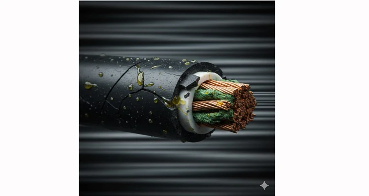
Two years ago, a diagnostic case landed in our lab: a bundle of wiring harnesses pulled from fertilizer spreaders, all failing with intermittent CAN bus faults. The OEM’s records pointed to an ISO 16750-3 vibration certificate from their supplier. Yet, the physical evidence—cracked jackets, brittle insulation, and copper conductors tinged green—told a different story. The certificate wasn’t wrong; it was irrelevant. The true failure was synergistic degradation, where vibration and chemical attack operate in a destructive feedback loop, accelerating failure in a way standardized lab tests deliberately isolate and therefore miss. If your equipment endures mechanical agitation alongside corrosive fluids, dust, or vapors, this is the specific failure mode that catalog-spec wiring is destined to lose against. This guide details the forensic engineering methodology required to engineer a lasting defense.
Classifying the Attack Vectors: A Failure-Mode Taxonomy
The threat is not monolithic. It manifests through distinct physical-chemical attack vectors. Engineering an effective defense starts with diagnosing the dominant vector in your application.
Abrasive-Corrosive Slurry (e.g., Mining, Quarrying): Here, chemically active dust (sulfides, chlorides) functions as a grinding paste. Persistent vibration works this abrasive medium into the cable surface, performing a dual attack: it wears away the jacket while simultaneously mechanically impregnating the polymer matrix with corrosive agents. The dominant failure mode is accelerated fretting wear married to deep-seated chemical attack.
Direct Fluid Impingement with Thermal Cycling (e.g., Agricultural Spraying): This is a pulsed assault. Cycles of direct ionic fertilizer or herbicide blend exposure are followed by dry-down and engine heat. Vibration during the wet phase drives fluid into micro-pores. Subsequent thermal cycles then create a peristaltic pumping action, drawing the chemical deeper into the material. The failure mode is chemical wicking critically enabled by mechanical pumping.
Permeating Electrolytic Atmosphere (e.g., Marine, Wastewater): This is a gaseous, omnipresent siege. Salt spray or H₂S vapors create a pervasive electrolyte. Vibration performs a dual role: it prevents the stabilization of any protective surface layer and constantly strains the molecular bonds in the polymer jacketing, making them kinetically more vulnerable to chemical chain scission. The failure mode is environmental stress cracking initiated and propagated by cyclic loading.
In these environments, a cable qualified only for an isolated vibration test possesses a fatal blind spot. The synergistic interaction is the primary failure mechanism.
The Failure Cascade: A Four-Stage Attack Sequence
Conventional qualification treats vibration and corrosion as independent stressors. In service, they execute a coordinated, cascading assault. This is the four-stage sequence we consistently map in our failure analysis lab.
Stage 1: Mechanical Incursion (The Beachhead).
Micromotion at clamp points (fretting) or resonant bending doesn’t cause an immediate electrical open. Its function is micro-fatigue: creating a network of sub-surface cracks and stress concentration points within the polymer jacket. This establishes the initial, invisible breach.
Stage 2: Chemical Infiltration & Molecular Interaction.
Corrosive agents are now drawn into this compromised matrix via capillary action. They do not sit inertly; they interact on a molecular level. They leach plasticizers, catalyze polymer chain scission (hydrolysis), or induce osmotic swelling. The jacket’s core mechanical properties—tensile strength, elongation—are degraded from within.
Stage 3: Brittle Fracture Propagation (The Cascade).
The now-embrittled or structurally compromised jacket can no longer effectively dissipate strain energy. The original micro-cracks propagate catastrophically under the continuing vibration load. A subsurface flaw transitions into a macroscopic breach, exposing the primary insulation.
Stage 4: Conductor Compromise (The Final Fault).
The assault reaches the copper. This culminates in copper creep corrosion, where conductive copper salts bridge across insulation surfaces to create leakage paths and short circuits, or in direct embrittlement fracture of annealed strands. The electrical fault is the terminal symptom, not the root cause.
Laboratory sequential testing (vibration then corrosion) is fundamentally blind to the catalytic feedback loop between Stages 2 and 3—the loop that dictates actual field service life.
Engineering a Defense: A Forensic, Layer-by-Layer Methodology
Neutralizing this cascade requires shifting from component selection to integrated system architecture. Our process is derived from dissecting failures like the spreader cables.
Step 1: Execute a Forensic Environmental Audit.
We start with instrumentation, not estimation. This means deploying tri-axial accelerometers on your prototype or in-service equipment to capture the true, multi-axis vibration signature. In parallel, we require a physical sample of the exact chemical agent (the specific fertilizer blend, the mine slurry suppressant) for material exposure trials. Defense cannot be designed against an undefined threat.
Step 2: Architect a Multi-Layer Defense System.
With this empirical data, we engineer each stratum of the assembly to intercept a specific stage of the failure cascade.
Conductor (Target: Stage 4): To resist embrittlement, we specify a post-annealed, asymmetrical stranding geometry. This preserves the intrinsic ductility of the electrolytic copper by distributing flexural stresses evenly, preventing localized work-hardening foci and maintaining conductive integrity under high-frequency micro-bending.
Insulation (Target: Stages 2-3): To block chemical infiltration, we bypass generic materials. We select fluoropolymer-based dielectrics (e.g., ETFE) not for a vague “chemical inertness” claim, but for their dense, non-porous molecular structure that physically impedes ion migration and acts as a inherent water vapor transmission barrier.
The Critical Barrier (Target: Stage 2): For immersion or direct spray zones, we integrate a fusion-bonded, foil-polymer laminate. This is not an accessory wrap; it is a continuously sealed, concentric tube that functions as a hermetic vapor diffusion barrier, arresting the chemical advance at the insulation perimeter.
Outer Jacket (Target: Stage 1): This is the sacrificial shield. We compound a hybrid elastomer (e.g., a specified TPU/CPE alloy) engineered for a lower coefficient of friction against steel (reducing fretting energy) and formulated to undergo controlled cross-linking upon exposure to target chemicals, thereby increasing its surface hardness in situ as a defense mechanism.
Step 3: Fortify Every Interface and Termination.
The harness is only as reliable as its weakest point.
Connector Sealing: A standard molded boot is a compromise. We specify fully potted rear shells or multi-stage overmolds that encapsulate the wire-to-terminal transition, creating a solid, monolithic block that presents zero path for chemical penetration or vibration-induced fatigue. The choice of termination technology itself is critical, as detailed in our comparison of crimp vs solder for vibration reliability.
Strain Relief & Clamping: High-stress points are armored with woven aramid fiber sleeves impregnated with a chemical-resistant coating. Custom overmolds at cable entries use a material engineered to bond molecularly with both the connector housing and the cable jacket, eliminating micro-gaps that enable wicking.
Routing Strategy: We design harness layouts with a clear mandate: avoid “chemical sumps”—locations where spilled or sprayed fluids can pool, creating zones of prolonged chemical contact and stagnation.
Step 4: Validate Under Combined Assault.
This is the non-negotiable phase. The prototype is tested not sequentially, but under simultaneous, combined stress. In our integrated environmental chamber, the harness endures its real-world vibration profile while undergoing thermal cycling and exposure to a mist or splash of the actual chemical agent. Continuous Resistance Monitoring (CRM) detects the precise moment of initial strand fracture or insulation breakdown. The test runs to failure, empirically defining the margin of safety. This rigorous validation is formalized within our IATF 16949 PPAP zero-defect process for production.
Common Design Mistakes That Guarantee Failure
- Specifying a Generic “Chemical-Resistant” Jacket. “Chemical-resistant” is undefined. A jacket performing well against diesel fuel may catastrophically fail in a ketone-based solvent. The specification must name the agent.
- Ignoring Vibration in “Chemical-Only” Assessments. Selecting a thick, chemically inert but rigid cable often creates a new failure point: brittle fracture at the connector due to unmanaged resonant vibration.
- Using Adhesive-Lined Heat Shrink as a Primary Seal. Heat shrink tubing can act as a wick, drawing chemicals under its lip via capillary action and trapping them against the wire, accelerating localized corrosion.
- Neglecting the Connector Backshell. Investing in a robust cable then using a standard, unsealed connector invalidates the entire defense strategy at the most critical interface.
- Testing Components in Isolation. Qualifying a jacket with a chemical immersion test and the assembly with a separate vibration test generates a dangerously misleading safety factor. It misses the synergistic acceleration.
How to Know Your Solution Is Truly Robust
Demand evidence, not assertions. Success is proven by three deliverables:
- Empirical, Combined-Stress Test Report: A document showing the harness survived X hours of simultaneous vibration, thermal cycling, and chemical exposure with no deviation in electrical continuity (data from CRM).
- Post-Test Forensic Analysis Log: After testing, the harness is dissected. The insulator shows no swelling, cracking, or loss of elongation. Conductor strands remain bright and ductile. There is zero evidence of fluid ingress past the primary seals.
- Material-Specific Compatibility Data: The supplier provides lab-generated charts showing the exact materials used (jacket, insulation, sealant) have been tested against your specific chemical, reporting metrics like volume swell %, tensile strength retention, and elongation retention post-exposure.
A System, Not Just a Cable: The ArmorLink-Chem Defense Platform
For applications facing this dual threat, our core ArmorLink™ philosophy crystallizes into a dedicated architecture. While every solution is customized, the ArmorLink-Chem framework provides a validated foundation.
| System Layer | Standard Weak Point | ArmorLink-Chem Defense |
| Conductor | Work-hardening copper strands prone to brittle fracture. | DuctilityLock-C™ Stranding: Thermally processed for sustained flexibility, resisting embrittlement from micro-flexing and chemical exposure. |
| Insulation | PVC/XLPE degrades via plasticizer leaching and chemical absorption. | FluoroGuard™ Insulation: Primary insulation of ETFE or similar fluoropolymer for inherent, broad-spectrum chemical inertness and a non-porous moisture barrier. |
| Barrier | Nonexistent; fluids reach conductors. | VaporBlock™ Laminate: Optional sealed foil-polymer tape wrap for absolute fluid/vapor barrier in immersion-risk zones. |
| Outer Jacket | Single-material PUR; compromised by hydrolysis and abrasion. | ChemArmor™ TPU/CPE: Custom-compounded for the target chemical family, with high abrasion resistance and engineered hydrolysis resistance. |
| Termination | Crimp voids allow wicking and strand movement. | HermeticPot™ Seal: Fully potted rear connector or overmold, creating a solid, impermeable block that eliminates internal movement and ingress paths. |
This is not an off-the-shelf product. It is an engineered outcome, whether the required interface is a standard J1939 connector, a specialty right-angle configuration for tight spaces, or a custom hybrid design.
Frequently Asked Questions (FAQ)
Q1: Can’t I just specify a thicker jacket?
A thicker jacket of the wrong polymer chemistry merely postpones failure. It increases stiffness, which elevates bending stress at terminations under vibration, often creating new failure points. Material science is paramount; thickness is secondary.
Q2: We use a stainless steel braided conduit for protection. Is that sufficient?
Braided conduit excels at mechanical abrasion and crush protection. However, it is a permeable mesh. Fine corrosive mists and dust will permeate it. It is a physical shield, not a chemical barrier. The cable inside must be designed for the chemical environment.
Q3: How do you test for copper creep corrosion?
We conduct a specialized test adapted from IPC-TM-650 guidelines. Terminated samples are exposed to a corrosive vapor (e.g., sulfur-rich) in a heated chamber while insulation resistance between adjacent pins is continuously monitored. A drop in resistance signals the growth of conductive copper salts, a failure mode we’ve confirmed in mining and wastewater applications.
Q4: Are there certifications for this combined stress?
No singular industry standard like ISO 16750-3 governs the combined vibration-chemical environment. Reliability is demonstrated through application-specific testing protocols, like ours, grounded in your real-world operational data. This is where engineering judgment supersedes checkbox compliance.
Q5: What about extreme temperatures with this?
The fluoropolymer insulators at our core typically offer a continuous operating temperature range of -65°C to +150°C, building thermal resilience intrinsically into the chemical defense strategy. The jacket compound is selected with congruent high-temperature performance criteria.
Q6: How do you handle multiple, different chemicals?
We analyze the chemical cocktail to identify the “worst-case agent” for material selection. Sometimes a blend necessitates a compromise or a more exotic polymer like PFA. We present the material performance data and engineering trade-offs transparently to inform the decision.
Q7: This sounds expensive. When is it justified?
Calculate the fully-burdened cost of one machine downtime incident: lost revenue, service crew dispatch, and production delays. If recurrent wiring failures are the culprit, the elevated initial cost of a correctly engineered harness becomes insignificant. It is justified for any critical control, sensor, or power line where failure stops the machine. For a deeper analysis, see our guide on the true cost of custom cable engineering.
Q8: We have an existing machine with chronic failures. Can you retrofit a solution?
Yes. Provide a failed harness and a sample of the chemical agent. Our failure analysis will pinpoint the primary degradation mode. We then design, build, and validate a drop-in replacement harness applying these principles. The retrofit typically includes recommendations for clamp brackets or routing to reduce stress.
Initiate a Diagnostic Review
If you are tracing intermittent electrical faults to harnesses in harsh environments, you have diagnosed the symptom. The next step is root-cause analysis. Our process begins as it did with the spreader cables: with a failed sample and an SDS sheet.
WhatsApp Our Failure Analysis Lead: +86 1730 7168 662 to send images and begin a technical dialogue.
Formalize the Investigation: Use our Contact Page to upload harness drawings, environmental specifications, and failure histories for a structured engineering review.
As an IATF 16949-certified factory operating under ISO 14001 environmental management, our system is built not on distributing catalog items, but on closing reliability gaps. We replace the cycle of failure with a documented protocol of immunity. Let’s apply that protocol to your application.
